The Three-Electrode System in Voltammetry: A Complete Guide to Principles, Applications, and Optimization for Biomedical Research
This article provides a comprehensive guide to the three-electrode system, the cornerstone of modern voltammetric analysis.
The Three-Electrode System in Voltammetry: A Complete Guide to Principles, Applications, and Optimization for Biomedical Research
Abstract
This article provides a comprehensive guide to the three-electrode system, the cornerstone of modern voltammetric analysis. Tailored for researchers and scientists in drug development, we demystify the fundamental roles of the working, reference, and counter electrodes and explain the core principle of separating potential measurement from current flow. The scope extends from foundational concepts and step-by-step methodological setup to advanced troubleshooting, optimization strategies, and a critical comparison with two-electrode configurations. By synthesizing these four intents, this resource aims to empower professionals with the practical knowledge to obtain highly accurate and reproducible electrochemical data for applications ranging from biosensor development to mechanistic studies of redox-active drug compounds.
Beyond the Basics: Deconstructing the Three-Electrode System and Its Core Working Principle
In the realm of voltammetry research, the choice of electrode configuration is foundational to data integrity. While the two-electrode system offers simplicity, its fundamental architecture introduces significant limitations for precise electrochemical measurements. This technical guide delineates the inherent shortcomings of the two-electrode configuration by contrasting its operational principles with the three-electrode system, the established standard in rigorous electroanalysis. Supported by experimental data and circuit theory, we demonstrate how the two-electrode system's inability to isolate and control the working electrode potential compromises measurement accuracy, particularly in applications demanding high precision, such as drug development and kinetic studies.
The Core Principles of Electrode Systems in Voltammetry
Voltammetry encompasses a range of techniques used in analytical chemistry and various industrial processes where information about an analyte is obtained by measuring the current as the potential is varied [1]. The resulting plot of current versus applied potential, known as a voltammogram, serves as the electrochemical equivalent of a spectrum in spectroscopy, providing quantitative and qualitative information about species involved in redox reactions [2]. The design of the electrochemical cell used for these measurements is critical, with the two-electrode system representing the most basic configuration.
The Two-Electrode System Architecture
A two-electrode system consists of a single working electrode and a combined reference/counter electrode [3]. In this setup, the current-carrying electrodes are also used for sense measurements [4]. The physical configuration has the working electrode (W) and working sense (WS) leads connected to one electrode, while the reference (R) and counter (C) leads are connected to the second electrode [4]. This arrangement creates a single circuit that measures the complete voltage dropped by the current across the entire electrochemical cell, including the working electrode, electrolyte, and counter electrode [4].
The Three-Electrode System Architecture
The three-electrode system was developed to overcome the limitations of the two-electrode approach. This configuration employs a working electrode (where the reaction of interest occurs), a reference electrode (to provide a stable potential reference), and a counter or auxiliary electrode (to complete the current circuit) [5]. This system forms two distinct circuits: a polarization loop for current to pass through, and a separate measurement control loop for potential monitoring [6]. This separation is crucial—it allows the potential of the working electrode to be measured and controlled without interference from the current flowing through the cell [3].
Table 1: Fundamental Comparison of Electrode System Architectures
| Feature | Two-Electrode System | Three-Electrode System |
|---|---|---|
| Number of Electrodes | 2 | 3 |
| Circuit Design | Single circuit for both current and potential measurement | Two circuits: polarization loop and measurement control loop [6] |
| Potential Measurement | Voltage difference between working and combined reference/counter electrode [3] | Potential between working electrode and dedicated reference electrode [4] |
| Current Path | Between working and combined electrode [4] | Between working and counter electrodes [5] |
| Reference Electrode Function | Serves as both reference and current source/sink [3] | Provides stable potential reference without passing current [6] |
| Measured Voltage | Entire cell voltage [4] | Voltage at working electrode only [4] |
Diagram 1: Architecture of two vs. three-electrode systems. The two-electrode system measures full cell voltage, while the three-electrode system isolates working electrode potential.
Fundamental Limitations of the Two-Electrode Configuration
Inability to Control Working Electrode Potential
The most critical limitation of the two-electrode system is its fundamental inability to precisely control and measure the potential at the working electrode. Because the system measures the voltage across the entire cell, any changes in potential at the counter electrode directly interfere with the measurement [4]. In a two-electrode setup, the combined reference/counter electrode must serve dual purposes: providing a stable reference potential while simultaneously passing all the current required to balance the redox events at the working electrode [3]. This dual role creates an inherent conflict, as passing current through the reference electrode inevitably alters its potential.
Impact of Solution Resistance and Polarization
In a two-electrode configuration, the measured potential includes voltage drops across the solution resistance (iR drop) and any polarization occurring at the counter electrode [3]. The substantial current passing through the system results in solution voltage drop and polarization of the counter electrode, making the potential of the working electrode challenging to directly and accurately determine [3]. This effect becomes particularly problematic in low-conductivity solutions or when measuring high currents, where iR drops can be substantial and lead to significant measurement errors.
Counter Electrode Limitations and System Instability
When the working and counter electrodes are of similar size, as is common in miniaturized systems or in vivo measurements, the electrochemical response can become dictated by the rate-limiting charge transfer step at either electrode [7]. This phenomenon can invalidate calibration curves, standard analytical methods, and equations, and even prevent the use of commercial simulation software [7]. The reference electrode in a two-electrode configuration cannot maintain a well-poised potential when current flows, leading to potential drift over time and compromising long-term measurement stability [4].
Table 2: Experimental Evidence of Two-Electrode System Limitations
| Experimental Observation | Impact on Measurement Precision | Source |
|---|---|---|
| Rate-limiting charge transfer with similar-sized electrodes | Invalidates calibration curves and standard analytical methods [7] | In vivo electrochemistry studies |
| Measurement of entire cell voltage rather than working electrode potential | Inability to isolate reaction of interest; includes all interfacial potentials [4] | Potentiostat manufacturer technical notes |
| Potential drift in reference electrode when current flows | Unstable potential reference over time, especially in prolonged experiments [4] | Instrumentation application notes |
| Three-electrode system improves stability of impedance measurements | Enhanced measurement reliability for processes like DNA hybridization detection [7] | Biosensing research |
| Better compensation for impedance changes in three-electrode configuration | Improved dopamine detection in rat models compared to two-electrode configuration [7] | Neuroscience research |
Experimental Evidence: Comparative Studies
In Vivo Electrochemistry Limitations
Recent research on in vivo electrochemistry has highlighted significant challenges with two-electrode configurations. When electrodes are implanted in biological tissue for chemical sensing, electrophysiological recording, or stimulation, the configuration is often optimized for specific anatomy and biological outcomes rather than electrochemical performance [7]. Studies have demonstrated that in a two-electrode configuration with similar working and reference/counter-electrode sizes, the electrochemical response becomes dictated by the rate-limiting charge transfer step at either electrode [7]. This limitation is particularly problematic for implanted electrodes that must function clinically for decades, as biofouling, movement of encapsulating tissue, and insulation failure can further exacerbate these electrochemical challenges [7].
Biosensing and Analytical Applications
The effect of electrode configuration has been critically assessed in biosensing applications. Research on DNA hybridization detection at electrode surfaces found that a three-electrode system significantly improved the stability of impedance measurements compared to two-electrode configurations [7]. Similarly, dopamine detection in rat models demonstrated superior performance in a three-electrode configuration, which was better able to compensate for changes in impedance [7]. These findings are particularly relevant for biosensors used in chronic measurements, where the risk of electrode variation and degradation over time can substantially affect electrochemical function [7].
Battery and Energy Storage Research
In battery testing and development, three-electrode systems provide essential capabilities for accurately measuring and analyzing the electrochemical properties of battery electrodes [5]. Compared with traditional two-electrode systems, the three-electrode configuration enables researchers to better dissect electrode behavior and reaction kinetics in batteries [5]. This capability is crucial for material testing and pole-and-ear cell testing, where understanding the individual contributions of cathode and anode materials is essential for performance optimization [5].
The Scientist's Toolkit: Essential Research Reagent Solutions
Table 3: Key Research Reagents and Materials for Voltammetry Experiments
| Reagent/Material | Function/Application | Technical Considerations |
|---|---|---|
| Potassium Ferricyanide (K₃[Fe(CN)₆]) | Standard redox probe for electrochemical characterization [8] | Exhibits nearly reversible one-electron reduction (Fe³⁺ to Fe²⁺) at E⁰ = 0.36-0.45 V [8] |
| Potassium Chloride (KCl) | Supporting electrolyte to minimize solution resistance and ensure diffusion-controlled reactions [1] [8] | Concentration typically 0.1 M-1.0 M; ensures current is carried by electrolyte ions rather than analyte |
| Hexaammineruthenium(III) Chloride ([Ru(NH₃)₆]Cl₃) | Faradaic response measurement for electrode characterization [7] | Alternative redox probe with well-defined electrochemical behavior |
| Sodium Chloride (NaCl) | Physiological saline model for in vivo electrochemistry studies [7] | Preferred over phosphate buffers for platinum electrodes as phosphate adsorbs to platinum [7] |
| Degassed Saline Solution | Best in vitro model of in vivo electrochemistry for testing bionic electrodes [7] | Removal of oxygen prevents unwanted redox reactions that interfere with measurements |
| Nafion Solution | Binder for catalyst ink preparation in modified working electrodes [3] | Provides proton conductivity while anchoring catalyst materials to electrode surface |
| Isopropanol/Ethanol-Water Mixtures | Solvents for catalyst ink preparation and electrode cleaning [3] | Disperses samples well with sufficient surface tension to prevent ink overflow during coating |
Experimental Protocols: Methodology for System Comparison
Electrode Preparation and Cleaning Protocol
- Polishing Process: Working electrodes (e.g., 0.6 mm diameter platinum disc) are polished with 0.3 μm alumina slurry on Microcloth polishing cloth, then rinsed thoroughly with deionized water [7].
- Solvent Cleaning: For PCB-based gold electrodes, rinse in distilled water, followed by submersion in acetone and sonication at room temperature for 15 minutes [8].
- Final Rinsing: After sonication, discard acetone and rinse electrodes sequentially in double distilled water and ethyl alcohol [8].
- Drying Process: Gently dry electrodes with clean tissue and blow-dry using nitrogen gas, followed by oven drying for 10 minutes at 50°C [8].
Solution Preparation and Degassing
- Electrolyte Preparation: Prepare test solutions of 0.1 M NaCl or other appropriate electrolytes using double distilled water as the base solvent [7] [8].
- Redox Probe Addition: For faradaic response measurements, add 5 mM Ru(NH₃)₆Cl₃ or 1-5 mM potassium ferricyanide to the test solution [7] [8].
- Degassing Procedure: Bubble inert gas (argon or nitrogen) through the solution for at least 10 minutes before performing electrochemistry to remove dissolved oxygen [7] [9].
System Configuration and Measurement
- Electrode Connection: Connect electrodes to potentiostat according to the chosen configuration (two- or three-electrode) [4].
- Open Circuit Potential Measurement: Measure open circuit potential for 10 seconds to establish baseline, with maximum change of 1 mV observed over this time period [7].
- Cyclic Voltammetry Parameters: Perform cyclic voltammetry over a potential range of -0.5 to +0.7 V (for ferricyanide) or 0.8 to -0.8 V (for platinum in saline) at a scan rate of 100 mV/s [7] [8].
- Impedance Spectroscopy: Perform EIS at 0 V vs. reference electrode with 5 mV amplitude over frequency range of 0.1 Hz to 1 MHz [7].
Diagram 2: Experimental workflow for electrode system comparison. Proper preparation is essential for reproducible electrochemical measurements.
The two-electrode system's architectural limitations present fundamental constraints for precise electrochemical measurements in research and drug development. Its inability to isolate the working electrode potential, vulnerability to solution resistance effects, and instability under current flow render it inadequate for applications requiring high precision. While the two-electrode configuration may suffice for simple measurements where whole-cell properties are of interest, the three-electrode system remains essential for rigorous electrochemical analysis where accurate potential control and measurement are paramount.
For researchers in drug development and analytical sciences, the choice of electrode configuration should align with measurement objectives. The three-electrode system provides the necessary precision for quantifying reaction kinetics, studying electrode mechanisms, and developing sensitive detection methods, making it indispensable for advancing electrochemical research and applications.
In the realm of modern electrochemistry, particularly in voltammetry research, the three-electrode system represents a fundamental technological advancement that enables precise control and measurement. This configuration is indispensable for investigating electrochemical reaction mechanisms, studying reaction kinetics, and developing sensitive analytical methods for applications ranging from battery design to drug development. Unlike the simpler two-electrode systems used in conventional batteries, the three-electrode setup separates the functions of potential measurement and current control, thereby overcoming significant limitations that previously hindered accurate electrochemical investigations [10].
The evolution from two-electrode to three-electrode systems in the 1920s addressed critical challenges in electrochemical research. In early two-electrode configurations, voltage drops from solution resistance and polarization of the counter electrode obscured the true potential at the working electrode, leading to considerable measurement errors [10]. The introduction of a reference electrode created the now-standard three-electrode system, which dramatically improved the precision and reproducibility of electrochemical experiments [10]. This innovation forms the foundation upon which modern voltammetric techniques are built, including cyclic voltammetry (CV), electrochemical impedance spectroscopy (EIS), and various stripping voltammetry methods essential for analytical applications.
In this technical guide, we will explore the fundamental principles, specifications, and experimental considerations for each component of the three-electrode system, with a specific focus on their applications in voltammetry research relevant to pharmaceutical and analytical scientists.
The Working Electrode (WE)
Definition and Primary Function
The Working Electrode serves as the stage where the electrochemical reaction of interest occurs. It is the central focus of voltammetric experiments, where electron transfer processes are both induced and monitored. The current measured at the working electrode corresponds directly to the redox behavior of the analyte system under investigation [10]. In voltammetry, the potential of the working electrode is carefully controlled relative to the reference electrode while the resulting current is measured between the working and counter electrodes, providing the characteristic current-potential responses that form voltammograms [11].
Key Characteristics and Material Selection
The selection of an appropriate working electrode is critical for obtaining meaningful voltammetric data. An ideal working electrode must be chemically inert relative to the electrolyte system, possess a reproducible surface state, and present a well-defined geometric area [10]. Different electrode materials yield different electrochemical windows (the potential range before electrolyte decomposition) and electron transfer kinetics, which must be considered when designing experiments.
Table 1: Common Working Electrode Materials and Their Applications in Voltammetry
| Electrode Material | Key Properties | Common Applications in Voltammetry |
|---|---|---|
| Glassy Carbon | Wide potential window, good mechanical properties, moderate cost | General purpose voltammetry, detection of organic molecules, electroanalysis |
| Platinum | Excellent conductivity, catalytic for many reactions, easily cleaned | Hydrogen evolution/oxidation, oxygen reduction, electrocatalysis studies |
| Gold | Good biocompatibility, well-defined surface chemistry | Biosensor development, protein studies, self-assembled monolayer research |
| Mercury | Renewable surface, high hydrogen overpotential | Stripping voltammetry for metal ions, dropping mercury electrode studies |
| Boron-Doped Diamond | Extremely wide potential window, low background current | Detection of difficult analytes, harsh environment applications |
| Carbon Paste | Modifiable surface, renewable, low cost | Customized sensors, bioelectrochemistry |
Experimental Considerations
Working electrode preparation significantly impacts experimental reproducibility. Surface pretreatment protocols must be standardized, typically involving mechanical polishing with alumina or diamond suspensions, followed by thorough rinsing [3]. For modified electrodes, ink preparation often involves dispersing the catalyst material with conductive additives and binders in an appropriate solvent [3]. The electrode surface area must be controlled and documented, as current responses in voltammetry are directly proportional to the electrode area according to the Randles-Sevcik equation [11].
The Reference Electrode (RE)
Definition and Primary Function
The Reference Electrode provides a stable, well-defined potential reference against which the working electrode potential is both measured and controlled [10]. This component is crucial because potential, by definition, cannot be measured absolutely but must be determined relative to a reference point [12]. In the three-electrode configuration, the reference electrode ideally draws negligible current, ensuring that its potential remains constant and unaffected by the electrochemical processes occurring in the cell [10] [11].
Key Characteristics and Common Types
A high-quality reference electrode exhibits stable potential over time, minimal temperature dependence, and well-defined composition that follows the Nernst equation [5]. The most common reference electrodes used in voltammetry are compared in the table below.
Table 2: Comparison of Common Reference Electrodes in Voltammetry
| Reference Electrode | Electrode Reaction | Potential vs. SHE (25°C) | Temperature Coefficient | Typical Applications |
|---|---|---|---|---|
| Standard Hydrogen Electrode (SHE) | 2H⁺ + 2e⁻ ⇌ H₂(g) | 0.000 V (by definition) | N/A | Theoretical standard, rarely used in practice |
| Saturated Calomel Electrode (SCE) | Hg₂Cl₂(s) + 2e⁻ ⇌ 2Hg(l) + 2Cl⁻ | +0.241 V | ~0.5 mV/°C | Aqueous electrochemistry, historical use |
| Silver/Silver Chloride (Ag/AgCl) | AgCl(s) + e⁻ ⇌ Ag(s) + Cl⁻ | +0.197 V (sat'd KCl) | ~0.5-1.0 mV/°C | Most common in modern research, biological systems |
| Hg/HgO | HgO(s) + H₂O + 2e⁻ ⇌ Hg(l) + 2OH⁻ | +0.098 V (1 M KOH) | Varies with [OH⁻] | Alkaline electrolyte studies |
Experimental Considerations
Proper reference electrode maintenance is essential for measurement accuracy. The reference electrode must be stored in an appropriate solution matching its internal composition (e.g., saturated KCl for Ag/AgCl) to prevent concentration gradients and potential drift [12]. During experiments, the reference electrode's Luggin capillary should be positioned close to the working electrode to minimize uncompensated solution resistance (iR drop), but not so close as to shield the working electrode surface [10]. For non-aqueous systems, special non-aqueous reference electrodes (such as Ag/Ag⁺ in acetonitrile) may be required [5].
The Counter Electrode (CE)
Definition and Primary Function
The Counter Electrode (also known as the auxiliary electrode) completes the electrical circuit in the electrochemical cell by providing a path for current to flow to balance the electron transfer occurring at the working electrode [10]. While the reference electrode controls potential without passing significant current, the counter electrode facilitates current flow between itself and the working electrode [10] [13]. In a typical voltammetry experiment using a potentiostat, current primarily flows between the working and counter electrodes, while the potential between the working and reference electrodes is precisely controlled [13].
Key Characteristics and Material Selection
The ideal counter electrode possesses several key characteristics: high electronic conductivity, chemical inertness in the electrolyte, and a surface area significantly larger than that of the working electrode [10] [3]. The large surface area ensures that the current density at the counter electrode remains low, minimizing its polarization and preventing it from becoming the limiting factor in the electrochemical experiment [10].
Common counter electrode materials include platinum wire or mesh, graphite rods, and sometimes gold or other inert metals [3]. Platinum is widely used due to its excellent conductivity and chemical stability across a wide potential range, though researchers should be cautious of possible platinum dissolution and deposition on the working electrode in prolonged experiments [3]. In such cases, graphite rods often serve as a suitable alternative [3].
Experimental Considerations
Counter electrode selection and placement require careful consideration. The electrode must be physically separated enough to avoid creating current hot spots yet positioned to ensure uniform current distribution. In some specialized applications, the counter electrode may be placed in a separate compartment with a frit to prevent reaction products from interfering with processes at the working electrode [12]. The counter electrode should be routinely cleaned or replaced to maintain consistent performance, as surface fouling or degradation can introduce artifacts in voltammetric measurements.
System Integration and Experimental Methodology
The Complete Three-Electrode Circuit
The integration of these three electrodes creates what is conceptually described as a "three-electrode, two-circuit" system [10] [3]. This arrangement effectively separates the potential measurement circuit (between working and reference electrodes) from the current-carrying circuit (between working and counter electrodes) [10]. A potentiostat enables this configuration by using feedback mechanisms to control the potential between the working and reference electrodes while measuring the resulting current between the working and counter electrodes [13].
The following diagram illustrates the complete three-electrode setup and the signal pathways:
Experimental Protocol: Cyclic Voltammetry with a Three-Electrode System
Cyclic voltammetry (CV) represents one of the most widely used voltammetric techniques employing the three-electrode system. The following protocol outlines a standard CV experiment for characterizing redox processes:
Principle: The technique involves applying a linear potential sweep to the working electrode (relative to the reference electrode) and measuring the resulting current (flowing between the working and counter electrodes). The potential is swept back and forth between two set values, creating the characteristic cyclic voltammogram that provides information about redox potentials, electron transfer kinetics, and diffusion characteristics [11].
Step-by-Step Procedure:
Electrochemical Cell Assembly: Prepare an electrochemical cell (typically a three- or five-neck glass vessel) containing the electrolyte solution. The electrolyte should be purified and degassed if oxygen-sensitive reactions are anticipated [3].
Electrode Preparation:
- Working Electrode: Polish the electrode surface with appropriate abrasive slurry (e.g., 0.05 μm alumina), rinse thoroughly with purified water or solvent, and dry [3]. For modified electrodes, apply the catalyst ink (catalyst, conductive carbon, binder, and solvent) in multiple layers to achieve the desired loading [3].
- Reference Electrode: Verify the potential stability of the reference electrode and ensure it contains the proper filling solution without air bubbles.
- Counter Electrode: Clean the counter electrode (e.g., by flame annealing for platinum or sonicating in solvent) to remove any contaminants.
Electrode Placement: Position the three electrodes in the cell. Place the Luggin capillary of the reference electrode close to the working electrode surface (approximately 1-2 times its diameter away) to minimize uncompensated resistance without causing shielding effects [10].
Connection to Potentiostat:
- Connect the RED (working electrode drive) and ORANGE (working electrode sense) leads to the working electrode (often stacked together) [13].
- Connect the WHITE (reference electrode sense) lead to the reference electrode [13].
- Connect the GREEN (counter electrode drive) lead to the counter electrode [13].
Instrument Configuration:
Data Acquisition and Analysis:
- Initiate the potential sweep and record the current response.
- Analyze the resulting voltammogram for peak potentials (
Epa,Epc), peak currents (ipa,ipc), and peak separation (ΔEp) to extract thermodynamic and kinetic parameters [11].
The workflow for this experimental protocol is summarized below:
Essential Research Reagent Solutions and Materials
Successful voltammetry experiments require careful selection of reagents and materials. The following table outlines key components and their functions:
Table 3: Essential Research Reagents and Materials for Three-Electrode Voltammetry
| Component | Function | Examples & Selection Criteria |
|---|---|---|
| Supporting Electrolyte | Conducts current, minimizes migration, controls ionic strength | Tetraalkylammonium salts (for non-aqueous), KCl/KNO₃ (for aqueous); must be electroinactive in potential window |
| Solvent/Electrolyte System | Medium for electrochemical reactions, dissolves analytes | Water, acetonitrile, DMF, DMSO; choice depends on analyte solubility and required potential window |
| Redox Probe/Internal Standard | Validates electrode performance, calibrates potential scale | Ferrocene/Ferrocenium (non-aqueous), K₃Fe(CN)₆/K₄Fe(CN)₆ (aqueous); should exhibit reversible electrochemistry |
| Electrode Modification Materials | Enhances sensitivity, selectivity, or catalytic activity | Carbon nanotubes, graphene, metal nanoparticles, conductive polymers; selected based on target application |
| Binder/Immobilization Agents | Fixes modifiers to electrode surface | Nafion (cation exchanger), chitosan (biocompatible polymer), polyvinylpyrrolidone |
| Purging Gas | Removes dissolved oxygen (a common interferent) | Nitrogen, argon; high purity (≥99.99%) required for oxygen-sensitive systems |
The three-electrode system, comprising the working, reference, and counter electrodes, forms the foundational architecture for modern voltammetry research. Each component plays a distinct yet interconnected role: the working electrode serves as the stage for targeted electrochemical reactions, the reference electrode provides a stable potential benchmark, and the counter electrode completes the current pathway. This sophisticated arrangement, enabling separate control of potential measurement and current flow, has revolutionized our ability to probe electrochemical phenomena with exceptional precision.
Understanding the specific functions, material requirements, and proper integration of these three key players is essential for researchers designing robust electrochemical experiments. From fundamental studies of electron transfer kinetics to applied research in pharmaceutical analysis and sensor development, the three-electrode system continues to be an indispensable tool. As voltammetric techniques evolve toward nanoscale applications and real-time monitoring capabilities, the principles governing these three electrodes remain central to generating reliable, reproducible electrochemical data that drives scientific and technological advancement.
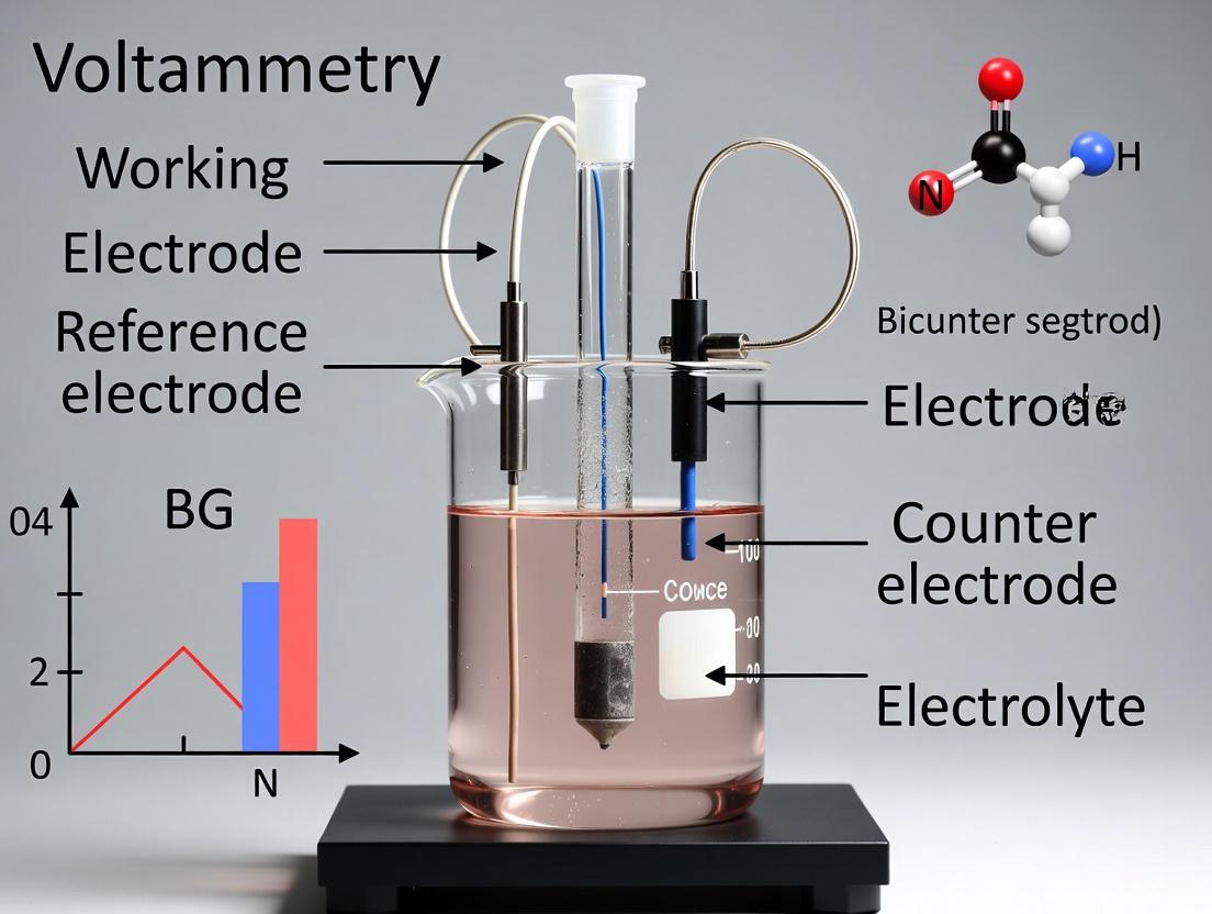
In electrochemical research, particularly in voltammetry, the three-electrode system is the fundamental configuration that enables precise and controlled investigation of redox processes. This system surpasses the simpler two-electrode setup by separating the functions of potential measurement and current control, thereby eliminating significant errors that arise from solution resistance (IR drop) and polarization of the counter electrode [10]. A typical three-electrode cell consists of a Working Electrode (WE), where the reaction of interest occurs; a Reference Electrode (RE), which provides a stable, known potential against which the WE potential is measured; and a Counter Electrode (CE), also known as the auxiliary electrode, which completes the circuit and allows current to flow through the cell without passing current through the reference electrode [10] [11] [6]. This arrangement forms two distinct circuits: a "potential circuit" between the WE and RE for accurate potential measurement and control, and a "current circuit" between the WE and CE for supplying and measuring the system current [10]. Understanding this architecture is crucial for appreciating the distinct roles and selection criteria for the different electrode materials, which are the focus of this technical guide.
Figure 1: Architecture of a three-electrode system showing the distinct roles of each component.
Electrode Fundamentals: Roles and Requirements
Working Electrode (WE)
The Working Electrode serves as the stage where the electrochemical reaction of interest is probed. Its material composition directly influences the reactions that can be observed, as it must provide an appropriate surface for electron transfer without interfering with or participating in unwanted side reactions [10] [6]. Essential requirements for an effective WE include being chemically inert relative to the electrolyte, possessing a reproducible and often renewable surface, and having a controlled geometric area to facilitate quantitative analysis [10]. Common materials include platinum, gold, glassy carbon, and mercury, each offering distinct advantages and limitations for specific electrochemical windows and reactions [10] [14] [6]. For instance, mercury electrodes are prized for their high hydrogen overpotential and renewable surface, albeit with toxicity concerns, while solid electrodes like platinum and gold require careful pretreatment to ensure reproducible surface states [14] [6].
Reference Electrode (RE)
The Reference Electrode is the cornerstone of potential control and measurement accuracy in the three-electrode system. Its primary function is to maintain a constant, well-defined electrochemical potential against which the potential of the working electrode is controlled and measured, ideally without passing any significant current [10] [6]. This is achieved by constructing the RE as a non-polarizable electrode, typically comprising a redox couple with constant concentrations of all components, such as Ag/AgCl in saturated KCl or Hg/Hg₂Cl₂ (calomel) in KCl solution [10] [15] [16]. A high-quality reference electrode must exhibit a stable and reproducible potential that is insensitive to small current flows, and it should be resistant to contamination from the test solution [15]. The stability of the RE potential is paramount, as any drift directly translates to inaccuracy in the controlled potential of the working electrode, compromising experimental data [10].
Counter Electrode (CE)
The Counter Electrode completes the electrical circuit in the electrochemical cell, serving as the source or sink for electrons to balance the current generated by reactions at the working electrode [10] [6]. Its primary role is to ensure that all current measured by the potentiostat originates from the working electrode, thereby enabling accurate current measurement for the process under study [10]. To perform this function effectively, the CE must be chemically inert under the experimental conditions to prevent dissolution or side reactions that could contaminate the solution. It should also possess high conductivity and a large surface area relative to the working electrode; this ensures that the counter electrode does not become the current-limiting component and minimizes its polarization, which could destabilize the system [10] [6]. Common choices include platinum wire or mesh and graphite, selected for their wide potential windows and stability [10].
In-Depth Analysis of Common Electrode Materials
Working Electrode Materials
Platinum (Pt) Electrodes Platinum is a widely used electrode material prized for its excellent electrical conductivity, chemical inertness, and catalytic properties. It is particularly valuable in electrocatalysis research, such as studies of the oxygen reduction reaction (ORR) in fuel cells, and for investigating surface processes like hydrogen adsorption/desorption [17]. A key application involves using cyclic voltammetry in acidic media to determine the electrochemically active surface area (ECSA) of platinum through hydrogen underpotential deposition (HUPD) [17]. A monolayer of adsorbed hydrogen corresponds to a charge of 210 μC cm⁻², allowing researchers to quantify active sites [17]. However, platinum's catalytic activity can be a drawback when studying reactions that might be catalyzed on its surface, potentially altering the natural mechanism. Its potential window is limited on the positive end by oxide formation and on the negative end by hydrogen evolution [14].
Gold (Au) Electrodes Gold electrodes share many beneficial properties with platinum, including high conductivity and chemical stability. Gold is often preferred over platinum for studies in positive potential regions because it generally has a higher overpotential for oxide formation, providing a wider anodic window [6]. This makes gold suitable for investigating anodic reactions and surface phenomena related to thiol-based self-assembled monolayers (SAMs). Like platinum, gold surfaces require careful preparation through polishing and electrochemical cleaning to achieve reproducible results. A limitation of gold is its relatively low hydrogen overpotential, which restricts its useful window for reductive processes compared to mercury electrodes [14].
Glassy Carbon (GC) Electrodes Glassy carbon stands as one of the most versatile working electrode materials due to its relatively wide potential window, low electrical resistance, and low porosity. It is composed of a vitreous, glass-like carbon material that offers excellent chemical inertness across a broad pH range [10] [6]. Glassy carbon is frequently the material of choice for studying organic electrochemistry and analytical detection methods because it exhibits minimal catalytic activity toward many redox reactions, allowing observation of the unaltered electron transfer process [10]. Its surface can be renewed through mechanical polishing with alumina slurries of decreasing particle size, followed by thorough rinsing. The usable potential window of glassy carbon is approximately -1.0 V to +1.0 V versus SCE in aqueous solutions, though this can vary with pH and electrolyte composition [10].
Table 1: Comparison of Common Working Electrode Materials
| Material | Key Advantages | Limitations | Common Applications |
|---|---|---|---|
| Platinum (Pt) | Excellent conductivity, catalytic properties, chemical inertness [6] [17] | Catalytic activity may interfere, limited anodic window due to oxide formation [14] | Electrocatalysis (ORR), hydrogen adsorption studies, fuel cell research [17] |
| Gold (Au) | High anodic overpotential, suitable for thiol chemistry, good conductivity [6] | Lower hydrogen overpotential, limited cathodic window [14] | Anodic reactions, self-assembled monolayers (SAMs) |
| Glassy Carbon (GC) | Wide potential window, low catalytic activity, chemically inert [10] [6] | Surface requires careful polishing, can be porous over time | Organic electrochemistry, analytical detection, general voltammetry [10] |
| Mercury (Hg) | High hydrogen overpotential, renewable surface [14] | Toxic, limited anodic window, easily oxidized [14] | Stripping analysis, studies at highly negative potentials [14] |
Reference Electrode Systems
Silver/Silver Chloride (Ag/AgCl) Electrode The Ag/AgCl reference electrode is one of the most commonly used reference systems in modern electrochemistry due to its simplicity, stability, and capability for miniaturization [15]. It consists of a silver wire coated with a layer of silver chloride (AgCl) immersed in an electrolyte solution containing a fixed concentration of chloride ions, typically potassium chloride (KCl) [15]. The electrochemical reaction is AgCl(s) + e⁻ ⇌ Ag(s) + Cl⁻, and its potential depends on the activity of the chloride ion in the internal solution. A saturated KCl solution gives a potential of approximately +0.197 V versus the Standard Hydrogen Electrode (SHE) at 25°C [15]. Ag/AgCl electrodes are robust and reliable for neutral solutions and weak acidic/basic environments (pH 1-8) but are not recommended for prolonged use in strong acids or bases, which can dissolve the AgCl layer or oxidize the silver wire [15]. Regular cleaning is advised, and the ceramic frit that forms the junction between the electrode and the test solution may require replacement if blocked [15].
Saturated Calomel Electrode (SCE) The Saturated Calomel Electrode (SCE) is a traditional reference electrode based on the calomel (mercury(I) chloride, Hg₂Cl₂) system. Its structure comprises elemental mercury in contact with a paste of mercury and calomel, submerged in a saturated potassium chloride solution [16]. The governing redox reaction is Hg₂Cl₂(s) + 2e⁻ ⇌ 2Hg(l) + 2Cl⁻, with a standard potential E° of +0.27 V [16]. The potential of the SCE is determined by the chloride ion activity, and for a saturated KCl solution at 25°C, it is +0.244 V versus SHE [16]. While the SCE has a reputation for robustness, its use has declined in many laboratories due to the toxicity of mercury, with Ag/AgCl electrodes often serving as a safer alternative [16]. Nevertheless, SCEs remain in use for specific applications, particularly in pH measurement and certain legacy methodologies.
Table 2: Comparison of Common Reference Electrodes
| Reference Electrode | Electrochemical Reaction | Potential vs. SHE (25°C) | Advantages & Limitations |
|---|---|---|---|
| Ag/AgCl (sat'd KCl) | AgCl(s) + e⁻ ⇌ Ag(s) + Cl⁻ [15] | +0.197 V [15] | Advantages: Simple, stable, miniaturizable [15]. Limitations: Not for strong acids/bases [15]. |
| Saturated Calomel (SCE) | Hg₂Cl₂(s) + 2e⁻ ⇌ 2Hg(l) + 2Cl⁻ [16] | +0.244 V [16] | Advantages: Robust, stable [16]. Limitations: Mercury toxicity [16]. |
| Hg/HgO | HgO(s) + H₂O + 2e⁻ ⇌ Hg(l) + 2OH⁻ | ~+0.098 V (1 M KOH) | Advantages: Ideal for basic solutions [15]. Limitations: Mercury toxicity, specific to alkaline media. |
| Ag/Ag⁺ (Non-aq.) | Ag⁺ + e⁻ ⇌ Ag(s) | Solution dependent | Advantages: Designed for non-aqueous electrolytes [15]. Limitations: Potential depends on Ag⁺ concentration. |
Selection Criteria and Experimental Design
A Framework for Electrode Selection
Choosing the appropriate electrode materials is a critical step in designing reliable and informative voltammetry experiments. The decision should be guided by the specific goals of the research, the properties of the analyte, and the experimental conditions. The following diagram outlines a logical workflow for this selection process.
Figure 2: A logical workflow for selecting appropriate electrodes in voltammetric research.
Key Selection Factors
Electrolyte Composition and pH: The chemical environment is perhaps the most critical factor. Ag/AgCl electrodes are ideal for neutral solutions but degrade in strong acids or bases, where Hg/Hg₂SO₄ or Hg/HgO are better choices, respectively [15]. For non-aqueous electrolytes, a reference electrode specifically designed for such systems, like Ag/Ag⁺, is required [15]. The electrolyte can also influence the voltammetric response on working electrodes, as different ions can structure water at the interface and affect the adsorption of reaction intermediates [18].
Potential Window Requirements: The required potential range dictates the choice of working electrode. For highly negative potentials, mercury or glassy carbon is preferable due to their high hydrogen overpotential [14]. For extensive positive potentials, gold or glassy carbon are suitable. Platinum's useful window is somewhat narrower due to oxide formation at positive potentials and hydrogen evolution at negative potentials [14].
Surface Properties and Reproducibility: The working electrode surface must be reproducible from experiment to experiment. Solid electrodes like Pt, Au, and GC require established pretreatment protocols, often involving mechanical polishing (e.g., with alumina slurry) and electrochemical cleaning (cycling in a clean electrolyte) to ensure a fresh, reproducible surface [6] [17]. The importance of a clean, well-defined surface is highlighted in studies determining the electrochemically active surface area (ECSA) of platinum, where the charge from hydrogen desorption is directly related to the number of surface adsorption sites [17].
Chemical Inertness and Catalytic Activity: The working electrode should not react with the solvent or electrolyte components [6]. Furthermore, its inherent catalytic properties must be considered. While platinum's high catalytic activity is beneficial for fuel cell research [17], it can be a disadvantage when studying a redox process in isolation, as it may catalyze unwanted side reactions. In such cases, a less active material like glassy carbon is often a better choice [10].
Essential Experimental Protocols
Protocol: Determining Electrochemically Active Surface Area (ECSA) of Platinum
The electrochemically active surface area (ECSA) is a critical parameter for quantifying the number of available catalytic sites on an electrode surface, particularly for materials like platinum used in electrocatalysis [17].
Research Reagent Solutions and Materials:
- Working Electrode: Rotating Disk Electrode (RDE) of platinum with a known geometric area (e.g., 0.0314 cm²) [17].
- Counter Electrode: Platinum wire [17].
- Reference Electrode: Saturated Calomel Electrode (SCE) [17].
- Electrolyte Solution: 0.25 M H₂SO₄, prepared from high-purity acid and distilled water [17].
- Polishing Supplies: Alumina powder slurry (various micron sizes) and polishing cloths [17].
- Degassing Gas: Argon or nitrogen for oxygen removal [17].
Detailed Methodology:
- Electrode Pretreatment: Polish the platinum working electrode thoroughly with alumina slurry (e.g., 0.05 µm) on a microcloth pad. Rinse sequentially with methanol and distilled water to remove all polishing residues [17].
- Cell Preparation: Place the cleaned electrodes in the electrochemical cell containing the 0.25 M H₂SO₄ electrolyte. Degas the solution by bubbling argon or nitrogen for at least 15 minutes to remove dissolved oxygen, which can interfere with the measurement [17].
- Instrumental Setup: Configure the potentiostat for Cyclic Voltammetry. Set the potential range to cover the hydrogen adsorption/desorption region (e.g., -0.2 V to +0.5 V vs. SCE) and the oxidation/reduction of the platinum surface. A scan rate of 20-50 mV/s is typical. Ensure the potential control resolution is optimized (e.g., by adjusting the E-range and potential step height) for accurate charge measurement [17].
- Data Acquisition: Run multiple cyclic voltammetry scans (e.g., 10 cycles) until a stable, characteristic voltammogram for platinum is obtained, displaying clear hydrogen adsorption/desorption peaks [17].
- Data Analysis:
- Isolate a stable cycle (e.g., the 10th cycle) for analysis.
- Identify the potential region for hydrogen desorption (anodic scan).
- Calculate the integrated charge (Q) in this region by integrating the current with respect to time (or potential, using Q = (1/ν)∫I dE, where ν is the scan rate) [17].
- Subtract the contribution from the capacitive double-layer current. This can be estimated by assuming a constant capacitive current across the integration window and subtracting the corresponding charge [17].
- The resulting charge (QH) corresponds to hydrogen desorption. The ECSA is calculated using the formula: ECSA = QH / (QRef × Ageo), where QRef is the charge density for a monolayer of hydrogen on a smooth Pt surface (210 μC cm⁻² is a common literature value) and Ageo is the geometric area of the electrode [17].
Protocol: Standard Cyclic Voltammetry of a Redox Couple
Cyclic Voltammetry (CV) is a fundamental technique for studying redox thermodynamics and kinetics. The following is a generalized protocol for a standard CV experiment [11].
Research Reagent Solutions and Materials:
- Working Electrode: Glassy carbon, platinum, or gold disk electrode.
- Counter Electrode: Platinum wire or coil.
- Reference Electrode: Ag/AgCl (for most aqueous solutions) or another suitable RE [15] [11].
- Electrolyte: A high-purity, inert supporting electrolyte (e.g., 0.1 M KCl, TBAPF6 in acetonitrile) at a concentration at least 100 times that of the analyte [19].
- Analyte: The redox-active species of interest (e.g., ferrocene for non-aqueous systems or potassium ferricyanide for aqueous systems).
- Degassing Gas: Argon or nitrogen.
Detailed Methodology:
- Electrode Preparation: Polish the working electrode meticulously with alumina slurry on a polishing cloth, followed by sonication in distilled water and rinsing to create a clean, reproducible surface.
- Solution Preparation: Prepare the electrolyte solution containing the analyte. Transfer it to the electrochemical cell.
- Degassing: Purge the solution with an inert gas (Ar or N₂) for 10-15 minutes to remove dissolved oxygen, and maintain a gentle gas flow over the solution during measurement to prevent oxygen re-entry [19].
- Instrument Configuration: Set up the potentiostat for CV. Define the initial, upper, and lower potential limits based on the redox couple under study. Set the scan rate (e.g., 100 mV/s for an initial experiment).
- Experiment Execution: Run the CV experiment. The potentiostat will sweep the potential linearly between the set limits, reversing direction at each vertex, for a set number of cycles.
- Data Interpretation: Analyze the resulting voltammogram. For a reversible system like ferrocene, look for symmetric anodic and cathodic peaks. The formal potential (E°) is approximated by the average of the anodic and cathodic peak potentials (Epa and Epc). The peak separation (ΔEp) should be about 59/n mV for a reversible, diffusion-controlled system at 25°C. The peak current (ip) is proportional to the concentration and the square root of the scan rate, as described by the Randles-Ševčík equation [11].
The judicious selection of electrode materials—Pt, Au, Ag/AgCl, SCE, and others—is not merely a procedural step but a foundational aspect of experimental design in voltammetry. The three-electrode system provides the architecture for precise measurement, but it is the careful matching of electrode properties to the research question, chemical environment, and desired potential window that ensures the acquisition of high-quality, reproducible data. As this guide has detailed, each electrode type brings a unique set of advantages and constraints. By applying a systematic selection framework and adhering to robust experimental protocols, researchers can leverage these material properties to unlock deeper insights into electrochemical mechanisms, material characteristics, and kinetic parameters, thereby advancing innovation in fields ranging from drug development to energy storage and materials science.
In electrochemical research, particularly in voltammetry, the accurate measurement and control of an electrode's potential are paramount. The fundamental parameter of interest in studies of reaction mechanisms, kinetics, and analyte concentration is the precise potential at the interface of the working electrode. Early electrochemical experiments relied on a simple two-electrode system, but these setups had significant drawbacks: the measured potential included unwanted voltage drops across the solution resistance and the counter electrode, obscuring the true potential at the working electrode interface [10]. This limitation introduced considerable errors, especially in systems with high current or low conductivity [3].
The introduction of the three-electrode system in the 1920s marked a revolutionary advance in electrochemistry [10]. Its core innovation is the "two-circuit" concept, which physically and electronically separates the function of potential control from the function of current flow. This separation allows researchers to precisely control and measure the potential of the working electrode without interference from other variables in the cell. For drug development professionals and researchers, this precision is non-negotiable, as it enables the reliable characterization of conductive polymers, pharmaceutical compounds, battery materials, and biosensors [11]. This guide explores the theory, setup, and application of this critical concept.
Fundamental Concepts: Voltage, Current, and Resistance
To understand the two-circuit concept, a firm grasp of basic electrical quantities is essential. These principles form the foundation of all electronic and electrochemical systems.
- Voltage (V) is the difference in electrical potential energy between two points, measured in volts (V). It is the "electrical pressure" that pushes electrons through a circuit [20] [21]. In an electrochemical cell, this potential difference drives electron transfer reactions.
- Current (I) is the rate of flow of electrical charge, measured in amperes or amps (A). It represents the quantity of electrons passing a point in the circuit per unit of time [22] [21]. In voltammetry, the Faradaic current is the direct response to the redox activity of an analyte.
- Resistance (R) is the opposition to the flow of current, measured in ohms (Ω). In a solution, this is influenced by the ionic conductivity of the electrolyte [22] [21].
The relationship between these three quantities is defined by Ohm's Law: ( V = I \times R ) [21]. In a two-electrode system, the current flowing through the cell (( I )) encounters the solution resistance (( Ru )), leading to a voltage drop known as the iR drop (( I \times Ru )). This uncompensated resistance means the potential applied by the potentiostat is not the true potential experienced at the working electrode interface, leading to distorted data [10] [3].
The Limitation of a Two-Electrode System
A two-electrode setup consists only of a working electrode and a counter electrode. In this configuration, the potentiostat both controls the potential and measures the current across this single pair of electrodes [3]. The fundamental limitation is that the potential being controlled and measured is the total cell potential—the sum of the potential differences across the working electrode interface, the solution resistance, and the counter electrode interface [4].
This setup presents two major problems for precise voltammetry research, as summarized in the table below.
Table 1: Key Limitations of a Two-Electrode System
| Limitation | Description | Impact on Measurements |
|---|---|---|
| Inability to Isolate Working Electrode Potential | The measured potential includes the potential of both the working and counter electrodes [4]. | The true potential driving the reaction at the working electrode is unknown, compromising thermodynamic and kinetic studies. |
| Solution Resistance (iR Drop) | Current flow through the resistive electrolyte causes a voltage loss (( I \times R_u )) that cannot be separated from the measurement [10]. | The applied potential is inaccurate; peak potentials shift in voltammetry, and reaction rates cannot be accurately determined. |
While two-electrode systems are suitable for devices like batteries and fuel cells where the total cell voltage is the parameter of interest [4], they are inadequate for fundamental studies of a single electrode's properties.
The Three-Electrode Solution: Core Components and the "Two-Circuit" Principle
The three-electrode system solves the inherent limitations of the two-electrode configuration by introducing a third, specialized electrode and, crucially, by separating the functions of potential control and current flow into two distinct electrical circuits [10] [3].
The Three Core Electrodes
The system comprises three electrodes, each with a specific, critical role.
Table 2: Roles and Specifications of the Three Electrodes
| Electrode | Primary Function | Common Materials | Critical Requirements |
|---|---|---|---|
| Working Electrode (WE) | The electrode where the reaction of interest occurs [10] [23]. | Glassy Carbon, Gold, Platinum, composite battery materials [10] [23]. | Chemically inert, reproducible surface, controlled geometric area [10]. |
| Reference Electrode (RE) | Provides a stable, known reference potential against which the WE potential is measured [10] [11]. | Ag/AgCl, Saturated Calomel (SCE), Hg/HgO [3] [23]. | Highly stable potential; ideally has negligible current flow to prevent polarization [10]. |
| Counter Electrode (CE) | Completes the current circuit with the WE, supplying the current required to balance the reaction at the WE [10] [23]. | Platinum wire/mesh, graphite rod [10] [3]. | Large surface area, highly conductive, and chemically stable to avoid becoming a limiting factor [10]. |
The "Two-Circuit" Conceptual Model
The "two-circuit" principle is the cornerstone of the system's precision. An electrochemical workstation (potentiostat) is fundamentally a four-probe instrument that can be configured to leverage this concept [4].
Diagram 1: The "Two-Circuit" Conceptual Model
The Potential Control Circuit (High-Impedance): This circuit is formed between the Working Electrode and the Reference Electrode. The potentiostat uses a high-impedance voltmeter to measure the potential difference between the WE and the RE [10] [3]. Because the RE draws negligible current, its potential remains stable and unaffected by the reactions in the cell. The potentiostat continuously adjusts the potential of the WE to maintain the user-defined value relative to this stable RE. This circuit is responsible for the precise potential control at the working electrode interface.
The Current Flow Circuit (Low-Impedance): This circuit is formed between the Working Electrode and the Counter Electrode. All the current generated by the electrochemical reaction at the WE flows through this path, measured by an ammeter [10] [3]. The CE's role is simply to supply or accept electrons to balance the charge, and its large surface area ensures it does not become polarized or limit the current. This circuit is responsible for accurate current measurement.
The physical setup of this system, showing how the potentiostat's leads connect to the three electrodes in the electrolyte cell, is illustrated below.
Diagram 2: Physical Setup of a Three-Electrode Cell
Practical Implementation and Methodologies
The Scientist's Toolkit: Essential Research Reagents and Materials
Successful implementation of a three-electrode system requires careful selection of components.
Table 3: Essential Materials for a Three-Electrode Voltammetry Experiment
| Item | Function | Examples & Notes |
|---|---|---|
| Electrochemical Workstation | Instrument that functions as potentiostat/galvanostat to control potential/current and measure the response [10] [3]. | Brands include Chenhua, Ivium, Gamry. Must have high precision (μV/nA), low noise [10] [3]. |
| Electrochemical Cell | Container for the electrolyte and electrodes where the experiment takes place [3]. | Typically a five-neck glass cell to accommodate three electrodes and gas inlets/outlets [3]. |
| Supporting Electrolyte | Conducts current and minimizes migration; provides a controlled ionic environment [23]. | Inert salts (e.g., KCl, KNO₃) at high concentration (>0.1 M) relative to analyte [11] [23]. |
| Solvent | Dissolves the analyte and supporting electrolyte. | Chosen for chemical compatibility; common examples are water, acetonitrile, isopropanol [3]. |
| Purging Gas | Removes dissolved oxygen, which can cause interfering redox reactions. | Inert gases like Nitrogen (N₂) or Argon (Ar) [3]. |
Detailed Experimental Protocol: Cyclic Voltammetry (CV)
Cyclic Voltammetry is a cornerstone technique that relies entirely on the precision of the three-electrode system. The following protocol outlines a standard procedure for characterizing a catalyst material, such as for the Hydrogen Evolution Reaction (HER).
1. Working Electrode Preparation:
- For catalyst inks: Weigh a specific amount of catalyst. For non-conductive catalysts, add conductive carbon black. Add a specific amount of Nafion binder (e.g., 5 wt%) and a solvent (e.g., isopropanol or ethanol/water mixture) to create an ink [3].
- Ultrasonicate the mixture for 20-30 minutes to ensure homogeneous dispersion [3].
- Using a micropipette, deposit a precise volume of the ink onto a pre-polished glassy carbon electrode.
- Dry the electrode at room temperature or under a mild heat lamp. If a high loading is required, apply the ink in multiple layers to avoid cracking [3].
2. Cell Assembly and Electrode Selection:
- Insert the prepared Working Electrode into one port of the electrochemical cell.
- Select an appropriate Reference Electrode based on electrolyte pH: Ag/AgCl for neutral, SCE for acidic, or Hg/HgO for alkaline solutions [3].
- Select a Counter Electrode that will not contaminate the system. A graphite rod is often preferable to platinum to avoid dissolution and deposition onto the WE during prolonged tests [3].
- Fill the cell with the electrolyte solution, ensuring all electrodes are immersed.
3. Pre-Test Procedures:
- Purging: Bubble an inert gas (N₂ or Ar) through the electrolyte for at least 30 minutes to remove dissolved oxygen [3].
- Placement: Position the tip of the Reference Electrode as close as possible to the surface of the Working Electrode without touching it. This minimizes the uncompensated solution resistance (Rᵤ) [10].
4. Instrument Configuration (e.g., for HER LSV):
- On the electrochemical workstation, select the Cyclic Voltammetry technique.
- Set Potential Parameters:
- Initial Potential (Estart): A potential where no faradaic reaction occurs.
- Vertex 1 (Evertex1): The most positive potential limit for the scan.
- Vertex 2 (E_vertex2): The most negative potential limit for the scan.
- Set Scan Parameters:
- Scan Rate (v): Typically 1-100 mV/s. The Randles-Sevcik equation shows that peak current (iₚ) is proportional to the square root of scan rate ((ip = (2.69 \times 10^5) n^{3/2} A D^{1/2} C v^{1/2})) for a reversible system [11].
- Number of Scans (Nscans): Typically 3-5 cycles to achieve a stable response.
5. Data Acquisition and iR Compensation:
- Initiate the scan. The potentiostat will control the WE potential relative to the RE (Potential Circuit) and measure the resulting current between the WE and CE (Current Circuit).
- After data collection, apply iR compensation to correct for the remaining solution resistance. This can be done manually (compensating 80-95% of the Rₛ measured via Electrochemical Impedance Spectroscopy) or using the instrument's automatic compensation function [3].
Applications in Research and Drug Development
The three-electrode system's precision makes it indispensable across scientific fields. In pharmaceutical and biomedical research, its applications are critical for advancing drug development and diagnostics.
- Drug Analysis and Quality Control: Electrochemical paper-based analytical devices (ePADs) leverage three-electrode designs for sustainable, smart, and portable drug measurement. They are used for quality control in pharmaceutical industries, assessing drug residues in wastewater and foodstuffs, and developing point-of-care testing devices for precision medicine [24].
- Characterization of Redox Mechanisms: Cyclic Voltammetry (CV) in a three-electrode setup is used to determine the thermodynamics of redox processes and energy levels of analytes. This is vital for understanding the redox behavior of drug molecules, which influences their metabolic stability and mechanism of action [11].
- In Vivo Sensing and Bionics: Three-electrode configurations are adapted for in vivo chemical sensing and stimulation. While two-electrode systems are sometimes used for miniaturization, the three-electrode system provides superior stability and compensates for changes in impedance, which is crucial for chronic measurements of neurotransmitters like dopamine in animal models [7].
The "two-circuit" concept embodied in the three-electrode system is a foundational principle in modern electrochemistry. By separating the roles of potential control (via the WE-RE circuit) and current measurement (via the WE-CE circuit), it overcomes the fundamental limitations of the two-electrode configuration. This separation enables the precise and accurate data required to unravel complex electrochemical processes. For researchers and drug development professionals, mastering this concept is not merely a technical exercise; it is a prerequisite for generating reliable, reproducible data that can drive innovation in material science, biosensor design, and pharmaceutical analysis.
In voltammetry research, the three-electrode system is a cornerstone for investigating electrochemical reactions, comprising a working electrode (WE), a counter electrode (CE), and a reference electrode (RE) [10]. While this configuration is fundamental for precise potential control and current measurement, the electrolyte in which these electrodes are immersed is equally critical. The electrolyte, typically a solution containing dissociated ions, serves two primary essential functions: it provides a medium for ionic conduction to complete the electrical circuit, and it minimizes overall solution resistance, thereby enhancing measurement accuracy and signal fidelity [1]. Without a properly selected electrolyte, even the most sophisticated three-electrode setup would fail to yield reliable electrochemical data. This article examines the fundamental roles of the electrolyte within the context of three-electrode voltammetry, providing researchers with practical guidance for optimizing electrochemical experiments.
Fundamental Principles of the Three-Electrode System
System Configuration and Function
The modern three-electrode system was developed to overcome the significant limitations of simpler two-electrode setups, primarily the difficulty in accurately controlling and measuring the potential of the working electrode [10]. Its operation can be understood through the "two-circuit" concept:
- The Potential Control Circuit: This loop involves the working electrode and the reference electrode. The reference electrode provides a stable, known potential against which the working electrode's potential is measured and controlled [10] [4]. Critically, this circuit carries negligible current, which prevents polarization of the reference electrode and maintains its stable potential [3].
- The Current Carrying Circuit: This loop consists of the working electrode and the counter electrode. The current generated from electrochemical reactions at the working electrode surface is balanced by the counter electrode, completing the electrical circuit [10] [1].
This separation of function is vital—it allows the instrument (potentiostat) to precisely control the potential of the working electrode relative to the reference electrode while independently measuring the resulting faradaic current flowing between the working and counter electrodes [1].
The Critical Role of the Electrolyte
The electrolyte serves as the essential physical medium that interconnects these three electrodes. Its primary functions include:
- Completing the Circuit: While electrons flow through the external wires between the working and counter electrodes, ionic current must flow through the solution via the movement of ions to maintain charge balance [1].
- Establishing Electrical Double Layers: At each electrode-electrolyte interface, a capacitive electrical double layer forms, composed of ions and oriented electric dipoles that counter the charge on the electrode surface [11]. The properties of the electrolyte directly influence this layer's structure and behavior.
- Enabling Mass Transport: Reactants must diffuse to the electrode surfaces, and products must diffuse away, processes governed by Fick's laws of diffusion and facilitated by the electrolyte medium [1].
Diagram 1: Ionic and electronic pathways in a three-electrode system, highlighting the electrolyte's role.
The Electrolyte as an Ionic Conductor
Mechanism of Ionic Conduction
In an electrochemical cell, electronic conduction occurs through the external metallic wiring, whereas ionic conduction occurs internally through the movement of ions within the electrolyte [1]. When a potential is applied, cations migrate toward the negatively charged cathode (where reduction occurs), and anions migrate toward the positively charged anode (where oxidation occurs). This ionic migration is the fundamental mechanism by which the electrolyte completes the internal electrical circuit, allowing the continuous flow of charge necessary for sustained electrochemical reactions.
The Necessity of Supporting Electrolytes
To ensure effective ionic conduction, a supporting electrolyte is used at a concentration typically 50-100 times greater than that of the analyte [1]. This high concentration of inert ions serves multiple purposes:
- Carrying the Current: The supporting electrolyte carries the majority of the ionic current, preventing mass transport limitations of the analyte and ensuring that the reaction kinetics of the species under study are not obscured by migration effects.
- Minimizing Migration: By ensuring the ionic strength is dominated by the supporting electrolyte, the contribution of electrical migration to the mass transport of the analyte becomes negligible. This simplifies the system to diffusion-controlled processes, making data interpretation more straightforward [1].
- Reducing Solution Resistance: As detailed in the following section, a high ion concentration directly lowers the solution resistance, which is crucial for accurate potential control.
Research Reagent Solutions: Essential Electrolyte Components
Table 1: Common Supporting Electrolytes for Voltammetric Studies
| Electrolyte | Common Concentrations | Typical Application Context | Primary Function |
|---|---|---|---|
| KCl | 0.1 M - 3.0 M | Aqueous solutions, fundamental studies [25] | Provides high ionic strength with minimal junction potentials; inert for many systems. |
| LiClO₄ | 0.1 M - 1.0 M | Non-aqueous (acetonitrile, DMF) [5] | High solubility in organic solvents; wide potential window. |
| TBAPF₆ (Tetrabutylammonium hexafluorophosphate) | 0.05 M - 0.1 M | Non-aqueous studies [1] | Provides a wide electrochemical window; minimal ion pairing. |
| Phosphate Buffered Saline (PBS) | 0.01 M - 0.1 M phosphate | Biological and pharmaceutical simulations [26] | Maintains constant pH; mimics physiological conditions. |
| H₂SO₄ | 0.1 M - 1.0 M | Acidic media studies, electrocatalysis (HER, OER) [3] | Provides acidic protons for reaction; high conductivity. |
| KOH | 0.1 M - 1.0 M | Alkaline media studies, electrocatalysis (OER) [3] | Provides hydroxide ions for reaction; high conductivity. |
Minimizing Solution Resistance
The Problem of Uncompensated Resistance
Despite the use of supporting electrolytes, all solutions possess an inherent solution resistance (Rᵤ), often termed uncompensated resistance. When current (I) flows through the cell, this resistance causes a voltage drop (iR drop) according to Ohm's Law (V = IR). This iR drop introduces a significant error: the potential sensed by the reference electrode differs from the true potential at the working electrode surface [10] [3]. This distortion can lead to inaccurate interpretation of voltammetric data, including widened peaks, shifted potentials, and incorrect kinetic analysis.
Strategies for Resistance Minimization
Researchers employ several strategies to minimize the impact of solution resistance:
- High Ionic Strength: Using a high concentration of supporting electrolyte (typically ≥ 0.1 M) is the most direct method to lower the solution's bulk resistivity [1].
- Proper Reference Electrode Placement: The reference electrode's tip (often via a Luggin capillary) should be positioned close to the working electrode surface to minimize the resistance in the potential sensing path [10] [5]. However, it must not be so close as to shield the working electrode surface and distort the current distribution.
- IR Compensation: Modern potentiostats offer electronic iR compensation techniques, which can be manual (applying a correction post-measurement based on known Rᵤ) or automatic (real-time positive feedback) [3]. While powerful, over-compensation can lead to instrument instability and must be applied cautiously [10].
Table 2: Impact of Solution Resistance on Voltammetric Measurements and Mitigation Strategies
| Observed Issue | Underlying Cause | Corrective Action |
|---|---|---|
| Peak separation in CV exceeds 59/n mV for a reversible system | iR drop distorting potential control | Increase supporting electrolyte concentration; apply iR compensation [3]. |
| Peak currents are lower than theoretically predicted | Excessive resistance limiting current | Use more conductive electrolyte; ensure proper electrode placement [10]. |
| Cyclic voltammogram peaks are asymmetrical or distorted | Non-uniform current distribution due to high Rᵤ | Reposition reference electrode with Luggin capillary; use higher ionic strength [5]. |
| Inconsistent results between different cell geometries | Variations in uncompensated resistance | Standardize cell design and reference electrode placement for reproducibility [10]. |
Experimental Protocol: Implementing a Three-Electrode System with Optimized Electrolyte
The following protocol outlines a standard procedure for conducting Cyclic Voltammetry (CV) using a potassium ferricyanide/ferrocyanide redox couple, a benchmark system for validating electrochemical setups [25].
Reagents and Materials
- Working Electrode: Glassy carbon, platinum, or gold disk electrode (diameter 1-3 mm) [26].
- Reference Electrode: Ag/AgCl (for aqueous systems) or Saturated Calomel Electrode (SCE) [3] [26].
- Counter Electrode: Platinum wire or coil [25] [3].
- Analyte Solution: 5 mM Potassium Ferricyanide (K₃Fe(CN)₆) and 5 mM Potassium Ferrocyanide (K₄Fe(CN)₆) [25].
- Supporting Electrolyte: 1.0 M Potassium Chloride (KCl) [25].
- Solvent: Deionized water.
- Electrochemical Cell: A single-compartment cell (e.g., 50 mL beaker or dedicated glass cell) with ports for the three electrodes [3].
- Potentiostat: Any modern electrochemical workstation capable of CV (e.g., Ivium, Chenhua, Gamry, or IEST systems) [3] [10].
Step-by-Step Procedure
Electrode Preparation:
- Polishing: Polish the working electrode sequentially with alumina slurries of decreasing particle size (e.g., 1.0 μm, 0.3 μm, and 0.05 μm) on a microcloth pad. Rise thoroughly with deionized water after each polish [26].
- Rinsing: Rinse all electrodes (WE, RE, CE) with deionized water and gently dry if necessary [25].
Electrolyte and Solution Preparation:
- Prepare the supporting electrolyte solution by dissolving 1.0 M KCl in 50 mL of deionized water.
- Add the redox analyte to the supporting electrolyte to create the final test solution (5 mM K₃Fe(CN)₆ / 5 mM K₄Fe(CN)₆ in 1 M KCl) [25]. The supporting electrolyte is now in great excess, ensuring minimal solution resistance and diffusion-controlled conditions.
Cell Assembly:
- Introduce approximately 30 mL of the final test solution into the electrochemical cell.
- Submerge the tips of the three electrodes into the solution.
- Critical Step: Position the reference electrode's tip close to the working electrode surface (approximately 2 times the diameter of the working electrode) using a Luggin capillary if available, to minimize uncompensated resistance [10] [5].
Instrument Connection:
- Connect the electrodes to the potentiostat as follows [13] [25]:
- Red Lead (Working Drive) → Working Electrode.
- Orange/Blue Lead (Working Sense) → Working Electrode (often stacked with the Red lead).
- White Lead (Reference Sense) → Reference Electrode.
- Green/Black Lead (Counter Drive) → Counter Electrode.
- Connect the electrodes to the potentiostat as follows [13] [25]:
Experiment Configuration and Execution:
- Select "Cyclic Voltammetry" in the instrument software.
- Set the parameters [3] [25]:
- Initial Potential: +0.6 V (vs. Ag/AgCl)
- Vertex 1 Potential: -0.1 V
- Vertex 2 Potential: +0.6 V
- Scan Rate: 50 mV/s (for initial test)
- Number of Scans: 2-3 (to ensure a stable response)
- Initiate the experiment. The resulting voltammogram should display the characteristic, symmetrical redox peaks of the ferri/ferrocyanide couple.
Diagram 2: Experimental workflow for three-electrode cell setup and cyclic voltammetry execution.
The electrolyte is far from a passive bystander in a three-electrode voltammetric experiment. Its dual role in providing robust ionic conduction and minimizing deleterious solution resistance is fundamental to obtaining high-quality, interpretable electrochemical data. The careful selection of the supporting electrolyte—considering its concentration, chemical compatibility, and potential window—is as critical as the choice of the three electrodes themselves. By understanding these principles and adhering to rigorous experimental protocols, such as proper electrode placement and the use of appropriate supporting electrolytes, researchers can ensure that their three-electrode systems function as intended. This enables the precise control and accurate measurement required to unravel complex reaction mechanisms, characterize new materials, and advance fields from drug development to energy storage.
From Theory to Practice: Setting Up Your Experiment and Key Applications in Biomedical Research
In voltammetry research, precise control and measurement of electrochemical reactions are paramount. While a two-electrode setup can be used in principle, it faces a significant limitation: it is difficult to maintain a constant potential while simultaneously measuring the resistance at the working electrode and passing the current necessary to counteract redox events [11]. The three-electrode system elegantly resolves this by separating the function of potential control from the function of current carrying [10] [4].
This separation is achieved through three distinct electrodes [10]:
- Working Electrode (WE): The electrode where the reaction of interest occurs.
- Reference Electrode (RE): Provides a stable, known potential against which the WE's potential is measured, without passing significant current.
- Counter Electrode (CE) (or Auxiliary Electrode): Completes the current circuit with the WE, allowing current to flow without affecting the potential measurement.
This guide provides a detailed, practical protocol for assembling a three-electrode electrochemical cell and connecting it to a potentiostat, enabling accurate and reproducible voltammetry research.
Components of the System
The Three Electrodes: Functions and Material Selection
The careful selection of electrode materials is critical for successful experimentation. The table below summarizes the roles and common material choices for each electrode.
Table 1: Electrode functions and common material choices in a three-electrode system.
| Electrode | Primary Function | Common Material Choices | Key Requirements |
|---|---|---|---|
| Working Electrode (WE) | Surface for the electrochemical reaction under study [10]. | Glassy Carbon, Platinum, Gold, Conductive Oxides (FTO/ITO) [10] [6]. | Chemically inert, reproducible surface, controlled geometric area [10]. |
| Reference Electrode (RE) | Provides a stable potential reference [10]. | Ag/AgCl, Saturated Calomel (SCE) [10] [5]. | Stable, well-defined potential; minimal current passage [10] [5]. |
| Counter Electrode (CE) | Completes the current circuit [10]. | Platinum, Graphite [10] [5]. | Large surface area, chemically stable, inert [10] [5]. |
Essential Reagents and Materials
Beyond the electrodes, a successful experiment requires several other key components.
Table 2: Essential research reagents and materials for three-electrode cell experiments.
| Item | Function / Explanation |
|---|---|
| Potentiostat | Instrument that controls the potential between WE and RE and measures the current between WE and CE [27]. |
| Electrolyte Solution | Contains supporting electrolyte to carry current; solvent and electrolyte salt must be electrochemically inert in the potential window of interest. |
| Electrochemical Cell | Container (e.g., beaker cell) holding the electrolyte and electrodes; must be inert to the solution [10]. |
| Connecting Cables & Clips | Typically alligator clips used to connect electrodes to the potentiostat's leads [13] [5]. |
| Redox Probe (e.g., Potassium Ferricyanide) | A standard analyte with a well-understood, reversible redox reaction used for system validation and characterization [8]. |
Assembly and Connection Procedure
Electrochemical Cell Assembly
Follow these steps to assemble the physical three-electrode cell:
- Prepare the Working Electrode: If using a solid electrode like glassy carbon, clean and polish the surface following a standardized pretreatment step to ensure reproducibility [10] [6].
- Add Electrolyte: Introduce the electrolyte solution containing your analyte into a clean, dry electrochemical cell [11].
- Position the Electrodes: Immerse the three electrodes into the electrolyte.
- Critical Placement: Position the tip of the Reference Electrode close to the surface of the Working Electrode. This minimizes the uncompensated solution resistance (IR drop), leading to more accurate potential control [10].
- Ensure the Counter Electrode is positioned sufficiently away from the WE to avoid shielding, but with enough surface area exposed to the solution [10].
- Secure the Setup: Use an appropriate stand or fixture to hold the electrodes firmly in place, preventing movement during the experiment [5].
Connecting to the Potentiostat
A potentiostat is fundamentally a four-probe instrument, meaning it has separate leads for driving current and sensing voltage [4]. The three-electrode configuration uses these leads in a specific way.
Diagram: Electrical connections and current pathways in a three-electrode system.
The diagram above shows the two distinct electrical circuits formed [10] [6]:
- The current circuit (Polarization Loop): Current flows between the RED (Working Drive) and GREEN (Counter Drive) leads via the Working and Counter Electrodes [13] [4].
- The potential circuit (Measurement Loop): The potential is measured and controlled between the ORANGE (Working Sense) and WHITE (Reference Sense) leads, which connect to the Working and Reference Electrodes [13] [4]. This sense loop draws negligible current, ensuring the Reference Electrode's potential remains stable [10].
Physical Connection Steps:
- Identify Leads: Locate the Working (Red), Working Sense (Orange), Counter (Green), and Reference (White) leads from your potentiostat cable [13] [4].
- Connect Working Electrode: Connect both the RED (Working Drive) and ORANGE (Working Sense) leads to the Working Electrode. This is often done by stacking the banana plugs together before attaching them to the electrode [13].
- Connect Counter Electrode: Connect the GREEN (Counter Drive) lead to the Counter Electrode.
- Connect Reference Electrode: Connect the WHITE (Reference Sense) lead to the Reference Electrode [13] [4].
- Final Check: Ensure all connections are secure and that no alligator clips are touching each other or the solution, which could cause a short circuit.
Experimental Protocols: Basic Voltammetry
With the cell assembled and connected, you can perform key electrochemical experiments. Cyclic Voltammetry (CV) is one of the most common techniques.
Cyclic Voltammetry (CV) of a Standard Redox Probe
Methodology:
- Solution Preparation: Prepare a solution of 1-5 mM potassium ferricyanide in a supporting electrolyte such as 0.1 M KCl [8]. Potassium ferricyanide ([Fe(CN)₆]³⁻) undergoes a reversible one-electron reduction to ferrocyanide ([Fe(CN)₆]⁴⁻), making it an ideal standard [8].
- Instrument Settings:
- Potential Window: Set an initial potential of -0.5 V and a upper potential of +0.7 V (vs. the reference electrode) [8].
- Scan Rate: Begin with a scan rate of 50-100 mV/s.
- Number of Cycles: Typically 3-5 cycles to observe stability.
- Data Collection: Run the experiment. The resulting plot of current (I) vs. potential (E) is a cyclic voltammogram.
- Expected Results: A well-functioning system will produce a "duck-shaped" voltammogram with symmetric anodic (oxidation) and cathodic (reduction) peaks. The formal potential (E⁰) is the average of the anodic (Epa) and cathodic (Epc) peak potentials and should be around 0.2-0.25 V vs. Ag/AgCl for ferricyanide [11] [8]. The peak current should be proportional to the square root of the scan rate, as described by the Randles-Ševčík equation [11].
Other Key Voltammetry Techniques
Table 3: Overview of key electrochemical techniques enabled by the three-electrode system.
| Technique | Principle | Key Application in Research |
|---|---|---|
| Electrochemical Impedance Spectroscopy (EIS) | Applies a small AC potential over a range of frequencies to measure impedance [10] [6]. | Resolves impedance characteristics of interface layers (e.g., SEI films in batteries) and analyzes charge transfer resistance [10]. |
| Galvanostatic Intermittent Titration Technique (GITT) | Applies a constant current pulse followed by a rest period [10]. | Measures chemical diffusion coefficients of ions within electrode materials, crucial for battery research [10]. |
| Chronoamperometry (CA) | Applies a constant potential step and measures current vs. time [6]. | Studies diffusion-controlled processes and reaction kinetics [6]. |
Troubleshooting and Best Practices
- Poor Reproducibility: Ensure consistent Working Electrode surface preparation (cleaning, polishing) before each experiment [10] [6].
- Noisy or Unstable Signal: Check that the Reference Electrode is properly conditioned and that the RE sense lead (white) has a secure connection. Allowing the potentiostat to warm up for 30 minutes before use can also improve signal stability [27].
- Distorted Voltammogram Shapes: This can be caused by a cell configuration issue. Verify that the Counter Electrode has a sufficiently large surface area and that the Reference Electrode is positioned close to the Working Electrode to minimize uncompensated resistance [10] [7].
- Important Safety Note: Always be aware of the chemical properties of your electrolytes and analytes. Use appropriate personal protective equipment (PPE) and follow all laboratory safety protocols.
Cyclic Voltammetry (CV) is a fundamental electrochemical technique wherein the current response of an electrochemical cell is measured while the potential between the working and reference electrodes is linearly swept back and forth between two limits at a defined rate [28]. The technique is indispensable for studying reaction mechanisms involving electron transfer, providing both qualitative and quantitative insights into redox processes [29].
The foundation of a reliable CV experiment is the three-electrode system, which overcomes the limitations of two-electrode setups by enabling precise potential control and accurate current measurement [30]. This system comprises:
- Working Electrode (WE): The electrode where the reaction of interest occurs. Its potential is controlled relative to the reference electrode and the current is measured at its surface. Common materials include platinum, gold, and glassy carbon [30].
- Reference Electrode (RE): This electrode maintains a stable, known, and fixed potential, providing a reference point against which the potential of the working electrode is precisely controlled and measured. Common examples are the Ag/AgCl and Saturated Calomel Electrode (SCE) [30].
- Counter Electrode (CE) or Auxiliary Electrode: This electrode completes the electrical circuit, allowing current to flow through the cell. It is typically made from an inert conductor like platinum wire or mesh [30].
The potentiostat is the instrument that applies the potential between the working and reference electrodes and measures the resulting current between the working and counter electrodes. This configuration ensures that the current does not pass through the reference electrode, thereby preserving its stable potential [28] [30]. Understanding this system is paramount, as all CV parameters are configured to interact with its fundamental principles.
Core Parameter Settings for a CV Experiment
Optimizing CV parameters is critical for obtaining high-quality, interpretable data. The key configurable parameters, their functions, and typical value ranges are summarized in the table below.
Table 1: Key Configurable Parameters in a Cyclic Voltammetry Experiment
| Parameter | Function & Purpose | Typical & Recommended Settings |
|---|---|---|
| Voltage Range / Window | Defines the upper and lower potential limits ((E1) and (E2)) of the scan. Must encompass all redox events of interest while avoiding solvent/electrolyte decomposition. | Aqueous systems: Often within ±2.0 V vs. OCP.Organic/Battery systems: Can extend to ±5.0 V.Best Practice: Ensure current approaches zero at voltage limits to minimize side reactions [31] [32]. |
| Scan Rate ((v)) | Controls the rate of potential change ((dE/dt)), directly influencing current response, peak separation, and kinetic information. | Conventional electrodes: 0.01 - 5 V/s [29].Standard studies: 0.1 - 10 mV/s [31] [32].Ultrafast microelectrodes: Can reach kV/s to MV/s ranges [29]. |
| Quiet Time / Stabilization Period | A delay before scanning to allow the electrochemical system to reach a steady state (e.g., potential stabilization, diffusion layer relaxation). | Typical Range: 5 - 60 seconds [32].Configurable Range: 1 - 100,000 seconds [32]. |
| Cycle Number | Number of repeated forward and reverse scans. Used to assess electrode stability, material cycling performance, and signal reproducibility. | Most experiments: 3 - 50 cycles [32].Configurable Range: 1 - 500,000 repetitions [32]. |
| Initial Potential ((E_i)) | The starting potential for the voltage sweep. Often set to the open-circuit potential (OCP) to begin from a state of zero current. | Configurable Range: Typically -10 V to +10 V [32]. |
The Critical Interplay of Scan Rate and Experimental Goals
The scan rate is among the most influential parameters, as it dictates the timescale of the experiment and the nature of the information obtained.
- High Scan Rates ((>100\ mV/s)): The rapid potential perturbation minimizes diffusion layer growth but increases charging current ((i{dl} = C{dl} \cdot v), where (C{dl}) is double-layer capacitance). This leads to greater observed peak separation ((\Delta Ep)) due to kinetic limitations and ohmic drop ((iR_u)). High scan rates are used to study fast reaction kinetics and short-lived intermediates [31] [29].
- Low Scan Rates ((<1\ mV/s)): The slow potential sweep allows the diffusion layer to develop more fully, minimizes double-layer charging effects, and allows the system to approach a quasi-equilibrium state. This results in smaller (\Delta E_p) and higher peak currents due to more complete reaction conversion [32].
For a typical experiment aimed at characterizing a new material, starting with a slow scan rate (e.g., (0.1\ mV/s) to (1\ mV/s)) is advisable to observe well-defined, low-polarization voltammograms. A multi-scan-rate study should then be performed to probe the reaction mechanism [32].
Experimental Protocols and Methodologies
Protocol 1: Standard Procedure for a Single-Scan-Rate CV
This protocol outlines the steps to obtain a basic CV curve for characterizing a redox couple.
- Cell Assembly: Assemble the three-electrode cell in an electrochemical vessel. For a battery material, this might involve a working electrode of active material coated on a current collector, a metallic lithium counter electrode, and a lithium wire reference electrode [31].
- Electrolyte Selection: Fill the cell with an appropriate electrolyte. For non-aqueous batteries, this is typically a (1\ M) salt (e.g., LiPF(6), NaClO(4)) in an organic solvent (e.g., EC/DEC, PC).
- Parameter Configuration:
- Set the Initial Potential to the open-circuit potential (OCP).
- Define the Voltage Range based on the known redox potentials of the active material. For example, a silicon-based anode may be scanned between (0.01) and (1.5\ V) vs. (Li/Li^+) [31].
- Set a moderate Scan Rate (e.g., (0.2\ mV/s) for battery materials or (10-100\ mV/s) for standard redox probes) [31] [29].
- Configure a Quiet Time of 10-30 seconds to allow potential stabilization [32].
- Set the Cycle Number to 3-5 to confirm reproducibility.
- Experiment Execution: Initiate the CV scan via the potentiostat (e.g., BioLogic, Autolab, CH Instruments) [30].
- Data Analysis:
- Extract the anodic peak potential ((E{pa})), cathodic peak potential ((E{pc})), anodic peak current ((i{pa})), and cathodic peak current ((i{pc})) from the most stable cycle.
- Calculate the peak potential separation (\Delta Ep = E{pa} - E{pc}). For a reversible, diffusion-controlled system with one electron transfer, this should be close to (59\ mV) at (298\ K) [29] [32].
- The formal redox potential is calculated as (E{1/2} = \frac{E{pa} + E{pc}}{2}) [32].
Protocol 2: Multi-Scan-Rate CV for Kinetic Analysis
This advanced protocol is used to determine the reaction mechanism (diffusion vs. capacitance control) and calculate kinetic parameters [32].
- Preliminary Steps: Follow steps 1-2 from Protocol 1.
- Parameter Configuration:
- Set the Voltage Range and Initial Potential as required for the system.
- Program a series of Scan Rates, typically increasing in a logarithmic progression (e.g., (0.1, 0.5, 1, 5, 10\ mV/s)) [31].
- Set a consistent Quiet Time and Cycle Number (e.g., 3) for all scans.
- Experiment Execution: Run the sequential CV experiments automatically.
- Data Analysis:
- Reversibility Assessment: For each scan rate, check if (\Delta Ep) remains constant and close to the theoretical value, indicating a reversible system. An increasing (\Delta Ep) with scan rate suggests quasi-reversible or irreversible behavior [29] [32].
- Diffusion Coefficient Calculation: For a reversible system, the peak current ((ip)) is related to the scan rate ((v)) by the Randles-Sevcik equation: [ ip = (2.69 \times 10^5) \ n^{3/2} \ A \ D^{1/2} \ C \ v^{1/2} ] where (n) is electron number, (A) is electrode area ((cm^2)), (D) is diffusion coefficient ((cm^2/s)), and (C) is bulk concentration ((mol/cm^3)). Plotting (ip) vs. (v^{1/2}) should yield a straight line, from which (D) can be calculated [31] [32].
- Control Mechanism Analysis: Plot (\log(ip)) vs. (\log(v)). The slope ((b)) of this plot indicates the current control mechanism:
- (b \approx 0.5): Reaction is dominated by semi-infinite diffusion control.
- (b \approx 1.0): Reaction is dominated by surface capacitance control (e.g., pseudocapacitance).
- (0.5 < b < 1.0): A mixed control regime [31].
The following workflow diagram illustrates the logical sequence and decision points in a multi-scan-rate CV experiment for kinetic analysis.
The Scientist's Toolkit: Essential Research Reagent Solutions
The selection of appropriate materials is as critical as parameter configuration. The table below details key components for a standard CV experiment.
Table 2: Essential Materials and Reagents for CV Experiments
| Item | Function / Role | Common Examples & Notes |
|---|---|---|
| Working Electrode | Provides the surface for the redox reaction. Material choice affects reactivity and background current. | Glassy Carbon (GC): General purpose.Platinum (Pt): For hydrogen reactions, excellent conductor.Gold (Au): For thiol monolayers.Carbon Paste: Easily modifiable surface [30]. |
| Reference Electrode | Provides a stable, known potential for accurate control/measurement of WE potential. | Ag/AgCl: Common in aqueous systems.Saturated Calomel (SCE): Aqueous systems.Li/Li+: Standard in non-aqueous Li-ion battery research [30] [31]. |
| Counter Electrode | Conducts current to balance the reaction at the WE. Must be inert. | Platinum wire/coil/mesh: Most common [30].Carbon rod/Graphite: Lower cost alternative. |
| Supporting Electrolyte | Carries current (via ion migration), minimizes ohmic drop ((iR_u)), and defines ionic strength. Must be electrochemically inert in the chosen window. | Aqueous: KCl, KNO₃, H₂SO₄, Phosphate Buffered Saline (PBS) [30].Non-aqueous: TBAPF₆, LiPF₆, NaClO₄ in organic solvents (ACN, DMF, EC/DEC) [33]. |
| Solvent | Dissolves electrolyte and analyte. Its electrochemical stability defines the usable voltage window. | Aqueous: Water (Window ~1.8 V).Non-aqueous: Acetonitrile (ACN), Dimethylformamide (DMF), Propylene Carbonate (PC) (Windows >4 V). |
| Redox Probe (for calibration) | Used to validate electrode performance and cleanliness via a well-understood reversible reaction. | Ferrocene/Ferrocenium (Fc/Fc+): Common reference in non-aqueous chemistry.Potassium Ferricyanide (K₃[Fe(CN)₆]): Common in aqueous chemistry. |
Advanced Considerations and Troubleshooting
Automation in Modern Electrochemistry
The field is moving toward increased automation to improve reproducibility, efficiency, and safety. Systems like ORGANA represent the cutting edge, using robotics and artificial intelligence to autonomously execute complex, multi-step electrochemical protocols. For instance, ORGANA can perform 19-step plans for characterizing redox flow battery molecules, including tasks like electrode polishing, which is critical for consistent results. This automation significantly reduces user time, physical demand, and operational variability [34].
Common Pitfalls and Data Validation
- Non-Ideal CV Curves: If peaks are broad, poorly defined, or show excessive peak separation, potential causes include high solution resistance (use more concentrated electrolyte), slow electrode kinetics (try slower scan rates), or a dirty/faulty working electrode (re-polish or replace) [31].
- Background Current: The total measured current ((i)) is the sum of Faradaic current ((iF)) from redox reactions and non-Faradaic capacitive current ((i{dl})) from double-layer charging. For electrodes with high surface area (e.g., nanomaterials), (i{dl}) can obscure (iF). It is good practice to run a "blank" CV of just the electrolyte and subtract it from the sample CV [31].
- Data Correlation: CV should not be used in isolation. The integral of the CV curve should match the voltage-capacity profile from galvanostatic charge-discharge (GCD) tests. Similarly, diffusion coefficients calculated from CV should be in the same order of magnitude as those derived from EIS (via Warburg impedance analysis) [31].
The three-electrode system is the cornerstone of modern voltammetry, enabling the precise potential control necessary for meaningful CV experiments. Proper configuration of parameters—from the strategic selection of scan rate to the adequate quiet time—is paramount for extracting accurate kinetic and thermodynamic data. As the field advances, the integration of automated systems and multi-technique validation will further solidify CV's role as an indispensable tool in electrochemical research.
In voltammetric research, the three-electrode system is the foundational configuration that enables precise and accurate electrochemical measurements. This system was developed to overcome the significant limitations of the simpler two-electrode setup, which struggled with inaccurate potential control due to factors like solution resistance (IR drop) and polarization of the counter electrode [3] [10]. The core advantage of the three-electrode system lies in its ability to separate the roles of potential measurement and current carrying, thereby allowing researchers to independently control and accurately measure the potential of the working electrode—the electrode where the reaction of interest occurs [10].
This "three-electrode, two-circuit" system forms two distinct electrical pathways [3] [10]:
- The Potential Circuit: A high-impedance voltmeter is connected between the working electrode (WE) and the reference electrode (RE). This circuit measures the potential of the WE against the known, stable potential of the RE without drawing significant current, thus ensuring an accurate reading [10].
- The Current Circuit: An ammeter is connected between the WE and the counter electrode (CE). This circuit is responsible for supplying or sinking the current required to drive the electrochemical reaction at the working electrode [10].
This separation is critical for interpreting voltammograms, as it ensures that the potential applied to the working electrode is known and controlled with high precision, and the resulting current is a clean measurement of the faradaic and non-faradaic processes at the electrode-solution interface.
The Essential Components and Their Functions
A functional three-electrode system requires specific components, each playing a distinct role. The table below summarizes the core elements of the "Scientist's Toolkit" for voltammetry research.
Table 1: Key Research Reagent Solutions and Materials in a Three-Electrode System
| Component | Examples | Function & Importance |
|---|---|---|
| Working Electrode (WE) | Glassy Carbon, Platinum, Gold, Carbon Paper [3] [10] | The site of the electrochemical reaction under study; its material and surface condition must be reproducible and inert [10]. |
| Reference Electrode (RE) | Ag/AgCl, Saturated Calomel Electrode (SCE), Hg/HgO [3] [10] | Provides a stable, known reference potential for accurate control and measurement of the WE potential [10]. |
| Counter Electrode (CE) | Platinum Wire/Mesh, Graphite Rod [3] [10] | Completes the current circuit by balancing the electron flow at the WE; should be chemically inert and have a large surface area [10]. |
| Electrolyte | Aqueous or non-aqueous salts (e.g., KCl, TBAPF₆) | Conducts current by ionic migration; its composition (pH, ionic strength) and degassing are crucial for controlling the electrochemical environment [3] [11]. |
| Potentiostat | - | The core instrument that applies the potential between WE and RE and measures the resulting current between WE and CE [11]. |
The following diagram illustrates the wiring and the fundamental "two-circuit" concept of a three-electrode system, connecting the components from Table 1.
Figure 1: The "Three-Electrode, Two-Circuit" Configuration. The potential is controlled and measured via the high-impedance loop between WE and RE (blue), while current is measured in the loop between WE and CE (red).
A Practical Protocol for Cyclic Voltammetry
Cyclic Voltammetry (CV) is a quintessential technique that leverages the three-electrode system to study redox processes. The following workflow outlines a standard experimental protocol for acquiring a CV, from initial setup to data collection [3] [11].
Experimental Workflow for a CV Measurement
Figure 2: Cyclic Voltammetry Experimental Workflow.
Step 1: Cell Assembly and Electrode Preparation Assemble a clean electrochemical cell (e.g., a five-neck glass vessel). Insert the three electrodes. The working electrode often requires careful preparation. For a catalyst ink, disperse the catalyst in a solvent (e.g., isopropanol) with a binder like Nafion, sonicate, and drop-cast a controlled volume onto a substrate like a glassy carbon electrode. Dry the electrode to form a film [3]. A self-supporting electrode can be used directly [3]. The surface of solid working electrodes should be cleaned and polished to ensure reproducibility [10].
Step 2: Electrolyte and Analyte Introduction Fill the cell with the supporting electrolyte. For studies involving dissolved analytes, add the compound of interest (e.g., 5 mM hexaammineruthenium(III) chloride) [35]. To remove dissolved oxygen, which can interfere with redox reactions, saturate the solution with an inert gas like nitrogen or argon for at least 10-30 minutes before and during testing [3] [35].
Step 3: Instrument Connection Connect the working, reference, and counter electrodes to their corresponding clamps on the potentiostat. Ensure the reference electrode is positioned close to the working electrode to minimize uncompensated solution resistance [10].
Step 4: Potentiostat Parameter Configuration In the instrument software, select the Cyclic Voltammetry technique and set the parameters [3]:
- Initial Potential (Estart): The starting voltage for the scan.
- Vertex Potentials (Vertex1, Vertex2): The upper and lower potential limits where the scan direction reverses.
- Scan Rate (v): The rate at which the potential is swept (e.g., 0.1 V/s to 1 V/s). This is a critical parameter affecting peak current and shape.
- Number of Scans (Nscans): Multiple cycles are often run to check for stability or surface conditioning.
Step 5: Experiment Execution and Data Acquisition Initiate the potential sweep. The potentiostat will automatically apply the triangular potential waveform and record the current response at the working electrode. The result is a plot of current (I) versus applied potential (E), known as a cyclic voltammogram [11].
Interpreting the Voltammogram: A Parameter-Based Approach
A cyclic voltammogram provides a wealth of information about the redox activity and kinetics of a system. The key to interpretation lies in identifying and analyzing specific features and their quantitative parameters.
Identifying Key Features on a Cyclic Voltammogram
A typical CV for a reversible redox couple displays a characteristic "duck-shaped" profile with distinct anodic and cathodic peaks [11]. The primary parameters to extract are:
- Anodic Peak Current (Ipa): The maximum current during the forward (oxidative) scan.
- Anodic Peak Potential (Epa): The potential at which Ipa occurs.
- Cathodic Peak Current (Ipc): The maximum current during the reverse (reductive) scan.
- Cathodic Peak Potential (Epc): The potential at which Ipc occurs [36].
The peak current is measured by extrapolating the baseline current and measuring the perpendicular height from this baseline to the peak top. The peak potential is read directly from the potential axis at the point of the peak maximum [36].
Quantitative Data and Diagnostic Criteria
The numerical relationships between these parameters are diagnostic of the nature of the electrode reaction. The following table consolidates the key quantitative criteria used to assess reaction reversibility and kinetics.
Table 2: Diagnostic Criteria for Interpreting Cyclic Voltammograms
| Parameter | Diagnostic Relationship | Significance & Interpretation |
|---|---|---|
| Peak Current Ratio | │Ipa/Ipc│ ≈ 1 [11] [36] | A hallmark of a reversible, diffusion-controlled electron transfer reaction. Significant deviation from 1 suggests follow-up chemical reactions or other mechanistic complexities. |
| Peak Potential Separation | ΔEp = │Epa - Epc│ ≈ 59/n mV (at 25°C) [11] [36] | For a reversible, one-electron (n=1) transfer, ΔEp is about 59 mV. Larger values indicate slower electron transfer kinetics (a quasi-reversible or irreversible system) [36]. |
| Peak Current vs. Scan Rate | Ip ∝ v¹/² [11] [36] | A linear relationship between the peak current and the square root of the scan rate indicates a reaction rate that is limited by the diffusion of the analyte to the electrode surface (diffusion-controlled). |
| Peak Potential vs. Scan Rate | Ep is independent of scan rate [11] [36] | For a reversible system, the peak potentials do not shift with changing scan rate. A shift in Ep with increasing scan rate is characteristic of quasi-reversible or irreversible reactions [36]. |
| Peak Current (Randles-Sevcik Equation) | Ip = (2.69×10⁵) n³/² A D¹/² C v¹/² (at 25°C) [11] | This equation quantitatively relates the peak current (Ip, Amperes) to fundamental parameters: the electrode area (A, cm²), diffusion coefficient (D, cm²/s), analyte concentration (C, mol/cm³), and scan rate (v, V/s). It is used for quantitative analysis. |
Advanced Application: Determining Reaction Reversibility
Using the criteria in Table 2, a researcher can systematically determine the reversibility of an electrode process, which is crucial for understanding reaction mechanisms, particularly in drug development for assessing the stability of redox-active molecules.
- Reversible Systems: Exhibit well-defined, symmetrical anodic and cathodic peaks with │Ipa/Ipc│ ≈ 1 and ΔEp ≈ 59/n mV. The peak potentials do not change with scan rate, and Ip is proportional to v¹/² [11] [36]. Ferrocene is a classic example of a reversible system often used as an internal standard [11].
- Quasi-Reversible Systems: The electron transfer kinetics are slow enough to cause observable deviations from reversibility. This manifests as ΔEp > 59/n mV, and the peak potentials will shift with increasing scan rate. The peak current is still primarily diffusion-controlled (Ip ∝ v¹/²) [36].
- Irreversible Systems: Only one peak (either anodic or cathodic) is typically present because the reverse reaction is too slow to occur on the experimental timescale. The peak potential shifts significantly with scan rate, and the peak current, while still proportional to v¹/², has a different coefficient in the Randles-Sevcik equation [11] [36].
The three-electrode system is the cornerstone of modern voltammetry, providing the necessary precision to deconvolute and quantify complex electrochemical reactions. By ensuring accurate potential control at the working electrode via a stable reference electrode and a separate current-carrying counter electrode, this setup yields high-quality voltammograms. As demonstrated, the interpretation of these voltammograms through key parameters—peak currents, peak potentials, and their dependence on scan rate—provides a rigorous framework for diagnosing reaction reversibility, elucidating mechanisms, and performing quantitative analysis. This systematic approach is indispensable for researchers and scientists, especially in fields like drug development, where understanding the redox properties of molecules is fundamental.
In voltammetric research, the three-electrode system is the fundamental configuration that enables precise and controlled investigation of electrochemical processes. This system was developed to overcome the significant limitations of the simpler two-electrode setup, which struggled with accurate potential measurement due to voltage drops from solution resistance and polarization of the counter electrode [3] [10]. The core innovation of the three-electrode system is its separation of potential measurement from current flow, creating what is often described as a "three-electrode, two-circuit" arrangement [3] [10]. This configuration is indispensable for extracting reliable kinetic and thermodynamic data, as it allows for the accurate control and measurement of the working electrode potential against a stable reference, independent of the current passing through the cell [10].
The system's operation can be conceptually understood as two distinct circuits managed by the potentiostat. A current meter is connected between the working electrode and counter electrode to measure the current generated by the electrochemical reaction, while a voltmeter is connected between the working electrode and reference electrode to precisely measure and control the potential at the working interface [3]. Since the reference electrode draws negligible current, its potential remains stable, providing a reliable reference point [10]. This separation is crucial because the current passing between the working and counter electrodes can be substantial, leading to solution voltage drop and polarization of the counter electrode, which would make the potential of the working electrode challenging to determine accurately without a dedicated reference electrode [3].
Fundamental Theory and Equations
The Nernst Equation: Thermodynamic Foundation
The Nernst Equation forms the cornerstone for understanding the thermodynamics of electrochemical systems, describing the relationship between the measured cell potential and the concentration of redox species under non-standard conditions [37]. It is derived from the principles of Gibbs free energy and relates the electrochemical potential to the reaction quotient.
For a general redox reaction, the Nernst Equation is expressed as: $$E = E^o - \frac{RT}{nF} \ln Q$$ [37]
At standard temperature (298 K), this simplifies to: $$E = E^o - \frac{0.0592\, V}{n} \log_{10} Q$$ [37]
Where E is the electrode potential, E⁰ is the standard electrode potential, R is the gas constant (8.3145 J·K⁻¹·mol⁻¹), T is temperature, n is the number of moles of electrons transferred in the reaction, F is the Faraday constant (96,485 C·mol⁻¹), and Q is the reaction quotient [37] [11].
The Nernst Equation is particularly valuable for determining equilibrium constants from electrochemical measurements. At equilibrium, where E = 0 and Q = K_eq, the equation transforms to: $$\log K_{eq} = \frac{nE^o}{0.0592\, V}$$ [37]
This relationship provides a direct method for calculating thermodynamic equilibrium constants from standard electrode potentials, where a positive E⁰ indicates a reaction that favors product formation (K > 1), and a negative E⁰ indicates a reaction favoring reactants (K < 1) [37].
The Randles-Sevcik Equation: Kinetic Insights
The Randles-Sevcik equation quantitatively describes the effect of scan rate on peak current in cyclic voltammetry experiments, providing critical insights into the kinetics of electrochemical processes [38]. This equation applies to electrochemically reversible systems where both reactants and products are soluble, such as the ferrocene/ferrocenium couple [38].
The general form of the equation is: $$i_p = 0.4463 \, nFAC \left( \frac{nF \nu D}{RT} \right) ^{\frac{1}{2}}$$ [38]
At 25°C (298 K), this simplifies to: $$i_p = (2.69 \times 10^5) \, n^{3/2} A C \sqrt{D \nu}$$ [38] [11]
Where i_p is the peak current (amps), n is the number of electrons transferred in the redox event, A is the electrode area (cm²), C is the concentration (mol/cm³), D is the diffusion coefficient (cm²/s), and ν is the scan rate (V/s) [38] [39].
The equation predicts that peak current increases with the square root of scan rate, which may seem counterintuitive initially. However, this relationship arises because faster voltage sweeps create steeper concentration gradients near the electrode surface, resulting in higher diffusion fluxes and consequently higher currents [38]. This principle forms the basis for determining diffusion coefficients and analyzing reaction mechanisms through systematic variation of scan rates.
Table 1: Key Parameters in Fundamental Electrochemical Equations
| Parameter | Symbol | Units | Role in Equation |
|---|---|---|---|
| Peak Current | i_p | Amps (A) | Dependent variable in Randles-Sevcik |
| Number of Electrons | n | Dimensionless | Stoichiometric factor in both equations |
| Electrode Area | A | cm² | Geometric factor affecting current |
| Concentration | C | mol/cm³ | Bulk concentration of active species |
| Diffusion Coefficient | D | cm²/s | Kinetic parameter for mass transport |
| Scan Rate | ν | V/s | Experimental variable in voltammetry |
| Standard Potential | E⁰ | Volts (V) | Thermodynamic reference point |
| Reaction Quotient | Q | Dimensionless | Ratio of product/reactant activities |
Experimental Protocols and Methodologies
Three-Electrode System Setup and Configuration
Establishing a proper three-electrode system requires careful selection and preparation of each component. The fundamental setup consists of:
Working Electrode (WE): This is the electrode where the reaction of interest occurs. Common materials include glassy carbon, platinum, gold, or carbon paper, depending on the application [3] [10]. The electrode surface must be clean and reproducible, with a controlled geometric area [10]. For catalyst studies, the working electrode is often prepared by creating an ink containing the catalyst, possibly conductive carbon black (for poor conductors), Nafion solution (binder), and a solvent like isopropanol or ethanol-water mixture [3]. This ink is then drop-cast onto the electrode substrate and dried [3].
Reference Electrode (RE): This electrode provides a stable, known potential reference point. Selection depends on the electrolyte pH: saturated calomel electrode (SCE) for acidic solutions, Ag/AgCl for neutral solutions, and Hg/HgO for alkaline solutions [3]. The reference electrode must be positioned close to the working electrode to minimize uncompensated solution resistance [10].
Counter Electrode (CE): Also known as the auxiliary electrode, it completes the current circuit and should have a large surface area to avoid becoming limiting. Common choices include platinum wire/mesh, graphite rods, or carbon rods [3] [10]. In some cases, platinum counter electrodes are avoided for prolonged tests to prevent artificial activity enhancement from Pt deposition on the working electrode [3].
The electrochemical cell itself is typically a five-neck glass reactor, allowing insertion of the three electrodes plus gas inlets/outlets if needed [3]. The electrolyte solution must be carefully prepared and degassed, often by bubbling inert gas (N₂ or Ar) for approximately 10 minutes to remove dissolved oxygen, which can interfere with measurements [3] [9].
Diagram 1: Three-Electrode System Setup Workflow
Cyclic Voltammetry Experimental Procedure
Cyclic voltammetry is one of the most powerful techniques for extracting both kinetic and thermodynamic information from electrochemical systems. The step-by-step protocol includes:
Instrument Preparation: Switch on the potentiostat approximately 30 minutes before measurements to allow it to warm up and reach a stable temperature [9].
Electrode Preparation: Clean the working and counter electrodes thoroughly using the same solvent as the electrolyte [9]. For functionalized electrodes, prepare the modified surface according to the specific requirements of the system.
Sample Application: For non-conductive samples, prepare a solution containing the analyte and place a droplet onto the tip of the working electrode, allowing it to dry [9].
Cell Assembly: Insert each electrode into the electrochemical cell cap and ensure proper positioning, with the reference electrode placed close to the working electrode to minimize uncompensated resistance [10].
Solution Degassing: Gently bubble inert gas (N₂ or Ar) through the solution for approximately 10 minutes using a thin tube or needle to remove dissolved oxygen [9].
Parameter Setup: In the potentiostat software, set the appropriate parameters including:
Measurement Execution: Withdraw the degassing tube and initiate the measurement via the software [9].
For systems requiring precise potential referencing, it's essential to convert measured potentials to the reversible hydrogen electrode (RHE) scale when reporting results, particularly for catalytic studies like the hydrogen evolution reaction (HER) or oxygen evolution reaction (OER) [3].
Data Analysis and Interpretation
Analyzing cyclic voltammetry data provides multiple insights into electrochemical behavior:
Reversibility Assessment: For a reversible system, the peak separation (ΔEp = Epa - E_pc) should be approximately 59/n mV at 25°C, and the ratio of anodic to cathodic peak currents should be close to 1 [9]. The formal potential (E⁰') can be estimated as the midpoint between the anodic and cathodic peak potentials [9].
Diffusion Coefficient Determination: Using the Randles-Sevcik equation, the diffusion coefficient (D) can be calculated from the slope of a plot of i_p versus √ν [38]. This requires knowing the concentration of the redox species and the electrode area.
Kinetic Information: Quasi-reversible systems show larger peak separations that increase with scan rate, while irreversible systems may display only one peak with the absence of a return wave [9].
Table 2: Key Measurements from Cyclic Voltammetry Experiments
| Measurement | Symbol | Extracted Information | Diagnostic Criteria | ||
|---|---|---|---|---|---|
| Anodic Peak Current | i_pa | Diffusion control, concentration | Proportional to √ν (Randles-Sevcik) | ||
| Cathodic Peak Current | i_pc | Diffusion control, concentration | ipa/ipc | ≈ 1 for reversible | |
| Anodic Peak Potential | E_pa | Oxidation thermodynamics | ΔEp = Epa - E_pc ≈ 59/n mV | ||
| Cathodic Peak Potential | E_pc | Reduction thermodynamics | ΔEp = Epa - E_pc ≈ 59/n mV | ||
| Half-wave Potential | E_1/2 | Formal redox potential | (Epa + Epc)/2 | ||
| Peak Separation | ΔE_p | Electron transfer kinetics | Increases with irreversibility | ||
| Onset Potential | E_onset | Reaction initiation barrier | Used for HOMO/LUMO estimation |
The Scientist's Toolkit: Essential Research Reagents and Materials
Table 3: Essential Materials for Three-Electrode Voltammetry Experiments
| Material/Reagent | Function/Purpose | Selection Criteria |
|---|---|---|
| Working Electrodes (Glassy carbon, Pt, Au, FTO/ITO) | Platform for electrochemical reaction of interest | Inertness, reproducible surface, controlled area [3] [10] |
| Reference Electrodes (Ag/AgCl, SCE, Hg/HgO) | Stable potential reference | Compatibility with electrolyte pH [3] |
| Counter Electrodes (Pt wire/mesh, graphite rod) | Complete current circuit | Large surface area, chemical stability [3] [10] |
| Supporting Electrolytes (LiClO₄, TBAPF₆, KCl) | Provide ionic conductivity | Non-coordinating, electrochemically inert, appropriate solubility |
| Solvents (Acetonitrile, DMF, Propylene Carbonate) | Dissolve analyte and electrolyte | Electrochemical window, analyte solubility, stability [40] |
| Redox Probes (Ferrocene, K₃Fe(CN)₆) | System validation and calibration | Well-defined electrochemistry, reversible behavior [11] |
| Nafion Solution | Binder for catalyst inks | Proton conductivity, stability in aqueous systems [3] |
| Conductive Additives (Carbon black) | Enhance conductivity of catalyst layers | For poorly conductive catalysts [3] |
Advanced Applications and Case Studies
Investigation of Electron Transfer Kinetics
The combination of Nernstian analysis and Randles-Sevcik kinetics provides a powerful approach for characterizing electron transfer processes. For electrochemically reversible systems, where electron transfer is fast compared to mass transport, the peak current ratio remains near unity and peak potentials remain constant with changing scan rate [38] [9]. However, as systems become quasi-reversible or irreversible, diagnostic deviations from ideal behavior emerge.
For irreversible systems, the electron transfer kinetics can be quantified by analyzing the shift in peak potential with scan rate. The transfer coefficient (α) and standard rate constant (k⁰) can be extracted using appropriate models that account for the kinetic limitations [9]. This analysis is particularly valuable in drug development for understanding the redox behavior of pharmaceutical compounds and their metabolic products.
Materials Characterization in Energy Research
The three-electrode system with cyclic voltammetry has become indispensable in energy materials research. For example, in characterizing conductive polymers for battery applications or catalysts for fuel cells, researchers can determine critical parameters including:
Electrochemical Stability Windows: Through repeated cycling, the stability of materials under operational conditions can be assessed [41].
Redox Potentials: The characteristic potentials for oxidation and reduction processes inform about the energetic landscape of the material [11].
Charge Storage Mechanisms: Differentiation between capacitive and diffusion-controlled processes through scan rate-dependent studies [11].
In one advanced application, researchers functionalized nanoporous TiO₂ with viologen molecules and Sb-doped SnO₂ with tetraphenylbenzidine (TPB) to create complementary hybrid electrodes for electrochromic devices [40]. Through careful three-electrode characterization, they optimized the system to achieve fast switching time constants of 0.5 seconds with high changes in optical density (ΔOD = 2.04), demonstrating the power of these methodologies in advanced materials engineering [40].
Determination of Diffusion Coefficients
A primary application of the Randles-Sevcik equation is the determination of diffusion coefficients for redox-active species. The experimental protocol involves:
- Performing cyclic voltammetry experiments at multiple scan rates (typically from 10 mV/s to 1000 mV/s)
- Measuring the peak current at each scan rate
- Plotting i_p versus the square root of scan rate (√ν)
- Calculating D from the slope of the resulting linear plot using the Randles-Sevcik equation [38]
This method provides a straightforward approach for quantifying mass transport parameters that are critical for understanding electrochemical systems ranging from biological electron transfer to battery performance.
Diagram 2: Diffusion Coefficient Determination Workflow
Troubleshooting and Method Validation
Even with carefully executed experiments, several factors can compromise data quality when using the three-electrode system:
Uncompensated Resistance (R_u): Solution resistance between working and reference electrodes can distort voltammograms, making reactions appear slower than they actually are [9]. This can be minimized by placing the reference electrode close to the working electrode and applying appropriate IR compensation [3] [10].
Charging Currents: The capacitive current associated with the electrical double layer can obscure Faradaic processes, particularly at fast scan rates [9]. These can be accounted for by subtracting background scans or using smaller working electrodes [9].
Reference Electrode Drift: Reference electrodes can experience potential drift over time, necessitating regular calibration against known redox couples such as ferrocene/ferrocenium [11].
Counter Electrode Limitations: Insufficient counter electrode surface area can lead to polarization, distorting measurements [10]. The counter electrode should have a significantly larger area than the working electrode.
Method validation should include regular testing with standard redox couples with known electrochemistry, such as ferrocene in non-aqueous systems or potassium ferricyanide in aqueous solutions [11]. These validation experiments confirm that the three-electrode system is functioning properly and that the extracted kinetic and thermodynamic parameters are reliable.
The integration of the three-electrode system with the theoretical frameworks of the Nernst and Randles-Sevcik equations provides researchers with a powerful methodology for extracting comprehensive kinetic and thermodynamic data from electrochemical systems. The three-electrode configuration's ability to precisely control potential while accurately measuring current enables the detailed investigation of electron transfer processes, mass transport phenomena, and reaction mechanisms.
When properly implemented with appropriate attention to experimental details—including careful electrode selection, proper cell configuration, and systematic data analysis—this approach yields invaluable insights across diverse fields from drug development to energy materials research. The continuing refinement of these methodologies ensures that voltammetric research remains at the forefront of analytical science, providing fundamental understanding of redox processes that underpin both biological and technological systems.
In voltammetry research, the three-electrode system represents a critical advancement beyond simple two-electrode setups, enabling unprecedented precision in studying electrochemical phenomena. This system functions by separating the processes of potential measurement and current application, thereby allowing researchers to exert exacting control over the working electrode's potential while accurately monitoring faradaic processes. The significance of this configuration lies in its ability to provide reliable, reproducible data on redox mechanisms, which form the basis for understanding drug metabolism, developing sensitive biosensors, and quantifying antioxidant activity. By providing a stable potential reference independent of current flow effects, the three-electrode system has become indispensable in modern electrochemical research across pharmaceutical and analytical applications.
The core configuration consists of three essential components: the working electrode (where the reaction of interest occurs), the counter electrode (which completes the circuit and balances current), and the reference electrode (which provides a stable potential benchmark) [30] [10]. This arrangement creates two distinct circuits within the system: a potential circuit between the working and reference electrodes for precise voltage control, and a current circuit between the working and counter electrodes for measuring faradaic response [10]. This "three-electrode, two-circuit" design effectively eliminates the voltage drops (IR drop) and polarization effects that plague two-electrode systems, making it particularly valuable for studying complex biochemical interactions where accurate potential control is paramount [10].
Fundamental Principles of the Three-Electrode System
System Components and Their Functions
The operation of the three-electrode system depends on specialized roles for each component, with specific material requirements to ensure optimal performance:
Working Electrode (WE): This electrode serves as the platform where the redox reactions of interest occur. Its surface properties directly influence the electron transfer kinetics and adsorption processes. Common materials include glassy carbon, platinum, gold, and increasingly, modified electrodes such as multi-walled carbon nanotubes (MWCNTs) which enhance sensitivity and provide superior electrocatalytic properties [30] [42]. The electrode must be chemically inert relative to the electrolyte and have a reproducible surface with controlled geometric area [10].
Reference Electrode (RE): This component provides a stable, known potential against which the working electrode potential is precisely controlled and measured. Unlike other electrodes, the reference electrode is designed not to polarize, maintaining a constant potential regardless of system conditions. Common reference systems include Ag/AgCl (silver/silver chloride), SCE (saturated calomel electrode), and Hg/HgO (mercury/mercury oxide) [30]. The critical requirement is that the reference electrode draws negligible current to prevent polarization that would compromise its stable potential [10].
Counter Electrode (CE): Also known as the auxiliary electrode, this component completes the electrical circuit with the working electrode, allowing current to flow through the cell. It typically consists of materials with high conductivity and chemical stability such as platinum wire or mesh, graphite rod, or carbon fiber [30] [43]. The counter electrode should have a larger surface area than the working electrode to ensure it does not become current-limiting [10].
Operational Principles and Instrumentation
The three-electrode system operates through sophisticated instrumentation, typically an electrochemical workstation or potentiostat, which manages the interplay between the electrodes. The potentiostat maintains the desired potential between the working and reference electrodes while measuring the resulting current flowing between the working and counter electrodes [10]. This separation of function is crucial—the reference electrode provides feedback to the potentiostat about the working electrode's potential without passing significant current, while the counter electrode supplies whatever current is necessary to maintain the set potential at the working electrode [44] [10].
The electrolyte solution forms an essential component of the system, providing ionic conduction between the electrodes. The choice of electrolyte depends on the research application, with common options including phosphate buffers, acetate buffers, and various salt solutions like KCl [43] [42]. The electrolyte must dissolve adequate supporting electrolyte to ensure good conductivity while being compatible with both the electrode materials and the analytes under investigation.
Table 1: Core Components of a Three-Electrode System
| Component | Primary Function | Common Materials | Critical Requirements |
|---|---|---|---|
| Working Electrode (WE) | Site for redox reaction of interest | Glassy carbon, platinum, gold, MWCNT-modified electrodes | Chemically inert, reproducible surface, controlled geometry |
| Reference Electrode (RE) | Provides stable potential reference | Ag/AgCl, SCE, Hg/HgO | Negligible current draw, non-polarizable, stable potential |
| Counter Electrode (CE) | Completes current circuit | Platinum wire/mesh, graphite rod | High conductivity, chemical stability, large surface area |
| Electrolyte Solution | Provides ionic conduction between electrodes | Phosphate buffers, acetate buffers, KCl solutions | Good ionic conductivity, analyte compatibility, chemical stability |
Investigation of Drug Redox Mechanisms
Experimental Approach to Elucidating Redox Behavior
The three-electrode system provides invaluable insights into drug redox mechanisms through techniques like cyclic voltammetry (CV) and differential pulse voltammetry (DPV). In CV, the potential is scanned linearly between set limits while measuring current response, generating characteristic peaks that reveal oxidation and reduction potentials [44]. These peak potentials indicate the thermodynamic feasibility of electron transfer, while peak currents reflect kinetic aspects of the redox process [43]. For example, research on vitamin C (ascorbic acid) using a glassy carbon working electrode demonstrated a single, irreversible oxidation peak at approximately 0.34V (vs. Ag/AgCl) in phosphate buffer (pH 7.4), corresponding to a two-electron oxidation process [43].
The relationship between scan rate and current response provides critical information about the reaction mechanism. For diffusion-controlled processes, the peak current (ip) increases linearly with the square root of the scan rate (v¹/²), following the Randles-Ševčík equation [44] [43]. This relationship was confirmed in vitamin C studies, where the linear dependence of ip on v¹/² indicated a diffusion-controlled process rather than surface adsorption [43]. Additionally, the Tafel slope derived from CV data offers information about the rate-determining step of the electrode reaction, with vitamin C exhibiting a Tafel slope of approximately 40mV [43].
Diagram 1: Drug Redox Mechanism Investigation Workflow
Quantitative Parameters for Mechanism Elucidation
Voltammetric experiments generate quantitative parameters essential for understanding drug redox behavior:
Peak Separation (ΔEp): The difference between anodic and cathodic peak potentials provides information about electron transfer kinetics. For a reversible system with fast electron transfer, ΔEp is approximately 59mV for a one-electron process, while larger values indicate quasi-reversible or irreversible systems [44].
Peak Current Ratio (Ipa/Ipc): The ratio of anodic to cathodic peak currents should approach unity for reversible systems, with deviations indicating follow-up chemical reactions or other mechanistic complexities [44].
Scan Rate Dependence: Analysis of how peak currents and potentials vary with scan rate distinguishes between diffusion-controlled and adsorption-controlled processes, with diffusion-controlled processes showing linear ip vs. v¹/² relationships [43].
Electron Transfer Number (n): For irreversible systems, the electron transfer coefficient (βnβ) can be calculated from the dependence of Ep on ln(v), as demonstrated in vitamin C studies where βnβ was determined to be 0.65 [43].
Table 2: Key Voltammetric Parameters for Drug Redox Mechanism Analysis
| Parameter | Definition | Interpretation | Application Example |
|---|---|---|---|
| Peak Potential (Ep) | Potential at maximum current | Indicates thermodynamic favorability of redox process | Vitamin C oxidation at +0.34V vs. Ag/AgCl [43] |
| Peak Separation (ΔEp) | Difference between anodic and cathodic Ep | Measures electron transfer kinetics; ~59mV/n for reversible systems | Polyphenolic compounds show 80-150mV separation [42] |
| Peak Current (Ip) | Maximum current during redox event | Proportional to analyte concentration; follows Randles-Ševčík equation | Linear ip concentration dependence for vitamin C [43] |
| Electron Transfer Number (n) | Number of electrons transferred | Calculated from peak width or scan rate dependence | Vitamin C oxidation involves 2 electrons [43] |
| Tafel Slope | Slope of Ep vs. log(scan rate) | Provides information on rate-determining step | Vitamin C Tafel slope ≈ 40mV [43] |
Development of Electrochemical Biosensors
Sensor Design and Optimization Strategies
Biosensor development heavily relies on the three-electrode system, where electrode modification plays a crucial role in enhancing sensitivity, selectivity, and stability. Nanomaterial-modified electrodes, particularly those incorporating carbon nanotubes, have demonstrated significant improvements in biosensor performance. For instance, inlaid multi-walled carbon nanotubes-modified graphite electrodes (MWCNTs/GE) provide superior electrocatalytic properties and charge transfer characteristics compared to conventional electrodes [42]. The fabrication process involves mechanically abrading MWCNTs onto the electrode surface, creating a stable, compact film that improves electrochemical response [42].
The three-electrode configuration is ideal for biosensor applications because it maintains stable potential control while measuring small current signals, which is essential for detecting low analyte concentrations. The reference electrode ensures the working electrode potential remains precisely controlled against biological variations, while the counter electrode handles current flow without affecting the measurement. This stability allows for accurate detection of biological molecules, including neurotransmitters, biomarkers, and DNA sequences, at clinically relevant concentrations.
Characterization and Performance Validation
Biosensor validation employs multiple electrochemical techniques within the three-electrode framework:
Cyclic Voltammetry (CV): Used to characterize the electroactive surface area and electron transfer kinetics of modified electrodes. The presence of redox peaks confirms successful modification and functionality [42].
Electrochemical Impedance Spectroscopy (EIS): Provides information about interface properties and charge transfer resistance, which decreases with successful electrode modification indicating improved electron transfer [45].
Differential Pulse Voltammetry (DPV): Offers enhanced sensitivity for quantitative detection by minimizing charging currents, making it ideal for measuring low analyte concentrations [43] [42].
For example, MWCNT-modified electrodes demonstrated excellent performance in detecting polyphenolic compounds, with DPV showing linear responses across concentration ranges from 2.0×10⁻⁶ to 8.0×10⁻⁴ g/L for gallic acid [42]. The modified electrodes exhibited well-defined oxidation peaks with minimal background current, highlighting their utility in biosensing applications.
Assessment of Antioxidant Capacity
Electrochemical Approaches for Antioxidant Evaluation
The three-electrode system provides a direct, efficient method for evaluating antioxidant capacity based on redox properties, offering advantages over conventional spectroscopic techniques like DPPH and FRAP assays [46] [47]. Electrochemical measurements directly probe the electron-donating ability of antioxidants, which correlates with their free radical scavenging activity [42] [47]. This approach has been successfully applied to various antioxidants, including polyphenolic compounds (gallic acid, caffeic acid, ferulic acid, vanillic acid) and vitamins [43] [42].
The fundamental principle involves measuring the oxidation potential and current of antioxidants, where compounds with lower oxidation potentials generally exhibit stronger antioxidant activity because they more readily donate electrons to neutralize free radicals [42]. For instance, studies show that gallic acid (oxidation potential +0.46V) demonstrates stronger antioxidant activity than vanillic acid (oxidation potential +0.63V), consistent with their radical scavenging capabilities [42]. The number and position of hydroxyl groups on phenolic compounds significantly influence their oxidation potentials and, consequently, their antioxidant efficacy [42].
Correlation Between Electrochemical Parameters and Antioxidant Activity
Voltammetric parameters provide quantitative measures of antioxidant capacity:
Oxidation Peak Potential (Epa): Lower values indicate greater ease of electron donation and stronger antioxidant potential [42].
Oxidation Peak Current (Ipa): Proportional to antioxidant concentration, allowing quantitative analysis [43] [42].
Number of Oxidation Peaks: Complex antioxidants may exhibit multiple peaks corresponding to sequential oxidation of different functional groups [42].
Research has established excellent correlation between electrochemical parameters and conventional antioxidant assays. For example, the radical scavenging activity of polyphenolic compounds follows the order: gallic acid > caffeic acid > ferulic acid > vanillic acid, which aligns perfectly with their increasing oxidation potentials determined by cyclic voltammetry [42]. This correlation validates electrochemical methods as reliable tools for rapid antioxidant capacity assessment.
Diagram 2: Antioxidant Capacity Assessment Methodology
Table 3: Electrochemical Assessment of Antioxidant Compounds
| Antioxidant Compound | Oxidation Potential (Epa) | Electrochemical Behavior | Correlation with Antioxidant Activity |
|---|---|---|---|
| Gallic Acid | +0.46V (vs. SCE) [42] | Single irreversible oxidation peak | Strongest activity due to multiple hydroxyl groups [42] |
| Caffeic Acid | +0.42V (vs. SCE) [42] | Quasi-reversible with Epc = +0.27V | Moderate activity with catechol structure [42] |
| Ferulic Acid | +0.37V (vs. SCE) [42] | Quasi-reversible with Epc = +0.26V | Moderate activity, methoxy substitution effect [42] |
| Vanillic Acid | +0.63V (vs. SCE) [42] | Quasi-reversible with Epc = +0.55V | Weakest activity due to single hydroxyl [42] |
| Vitamin C (Ascorbic Acid) | +0.34V (vs. Ag/AgCl) [43] | Irreversible one-step oxidation | Strong activity, two-electron oxidation [43] |
Essential Research Reagent Solutions and Materials
Successful experimentation with three-electrode systems requires careful selection of reagents and materials optimized for specific applications:
Table 4: Essential Research Reagents and Materials for Three-Electrode Systems
| Category | Specific Examples | Function and Application Notes |
|---|---|---|
| Working Electrodes | Glassy carbon (GC) electrode [43], Platinum electrode [30], Gold electrode [30], MWCNT-modified graphite electrode [42] | GC provides wide potential window; Pt and Au offer excellent conductivity; MWCNT modification enhances sensitivity and electrocatalysis |
| Reference Electrodes | Ag/AgCl (3M KCl) [43], Saturated calomel electrode (SCE) [42], Hg/HgO electrode [30] | Ag/AgCl popular for biological systems; SCE provides stable potential; store in proper electrolyte and rinse before use |
| Counter Electrodes | Platinum wire [43], Platinum mesh [30], Graphite rod [30] | High surface area to prevent current limitation; platinum offers excellent chemical stability |
| Buffer Systems | Phosphate buffer (pH 7.4) [43], Acetate buffer (pH 4.4) [42], Citrate-phosphate buffer [42] | Maintain pH stability; choice depends on analyte properties and biological relevance |
| Supporting Electrolytes | Potassium chloride (KCl) [42], Sodium phosphate [43] | Provide ionic conductivity without participating in redox reactions; concentration typically 0.1-1.0M |
| Electrode Preparation | Alumina suspension (0.05μm) [43], Methanol for rinsing [43] | Polishing creates reproducible surface; rinsing removes impurities and polishing residues |
Advanced Methodologies and Experimental Protocols
Cyclic Voltammetry for Mechanism Investigation
A standardized protocol for studying drug redox mechanisms using cyclic voltammetry involves:
Electrode Preparation: Polish the working electrode (typically glassy carbon) with alumina suspension (0.05μm) on microcloth pads, then rinse thoroughly with distilled water and methanol [43]. This ensures a clean, reproducible surface essential for consistent results.
Solution Preparation: Dissolve the drug compound in appropriate supporting electrolyte (e.g., 0.1M phosphate buffer, pH 7.4) at concentrations typically ranging from 2-6mM [43]. Deoxygenate the solution by purging with high-purity argon for 3-5 minutes to remove dissolved oxygen that could interfere with measurements.
Instrument Parameters: Set initial parameters including potential range (determined by preliminary scans), scan rates (typically 10-100mV/s), and number of cycles (usually 3-4 to establish stability) [43]. The potential window should encompass both oxidation and reduction events of interest.
Data Collection: Perform CV measurements at multiple scan rates to determine whether the process is diffusion or adsorption-controlled. For reversible systems, peak current should scale linearly with v¹/², while peak potential remains constant [44] [43].
Analysis: Determine key parameters including peak potentials (Epa, Epc), peak currents (Ipa, Ipc), and their ratios. Calculate the electron transfer number (n) and heterogeneous electron transfer rate constant (k°) where applicable [43].
Differential Pulse Voltammetry for Quantitative Analysis
For sensitive quantification of antioxidants or drugs, DPV offers enhanced resolution:
Parameter Optimization: Set pulse parameters including pulse size (typically 50mV), pulse time (0.1s), and sample period (0.5s) [43]. These parameters minimize charging currents while maximizing faradaic response.
Calibration Curve: Measure DPV responses across a concentration series to establish a linear relationship between peak current and concentration [42]. For example, gallic acid shows linear response from 2.0×10⁻⁶ to 8.0×10⁻⁴ g/L [42].
Sample Analysis: Apply the method to unknown samples using the standard addition method to account for matrix effects, particularly in complex biological samples [47].
Electrochemical Impedance Spectroscopy for Interface Characterization
EIS provides complementary information about electrode-solution interfaces:
Experimental Setup: Apply a small amplitude AC voltage (5-10mV) across a frequency range from 0.01Hz to 100kHz while measuring current response [45].
Data Interpretation: Analyze resulting Nyquist plots to extract interface parameters including charge transfer resistance (Rct), double-layer capacitance (Cdl), and solution resistance (Rs) [45].
Modified Electrodes: Use EIS to confirm successful electrode modification, typically indicated by decreased charge transfer resistance due to enhanced electron transfer properties [42].
The three-electrode system remains the cornerstone of modern voltammetric research, providing the precision and reliability required for studying drug redox mechanisms, developing advanced biosensors, and evaluating antioxidant capacity. Its unique configuration—separating potential control from current measurement—enables researchers to obtain detailed information about electron transfer processes that would be inaccessible with simpler two-electrode systems. As electrochemical applications continue to expand into increasingly complex biological systems, the fundamental principles of the three-electrode system will continue to underpin innovations in pharmaceutical research, diagnostic development, and nutritional science. The ongoing development of modified electrodes with enhanced sensitivity and selectivity promises to further extend the capabilities of this already versatile experimental platform.
Achieving Precision and Accuracy: A Troubleshooting Guide for Common Pitfalls and Optimization Techniques
In voltammetry research, the three-electrode system is the fundamental configuration that enables precise electrochemical measurements. This system consists of a Working Electrode (WE), a Reference Electrode (RE), and a Counter Electrode (CE) (also known as an auxiliary electrode) [10] [6]. Its primary purpose is to separate the function of potential control from the function of current carrying, a critical distinction that the simpler two-electrode system cannot achieve [10] [11].
In this arrangement, the working electrode is the site of the electrochemical reaction under investigation [10]. The reference electrode provides a stable, known potential against which the working electrode's potential is measured and controlled, ideally without passing any current [6]. The counter electrode completes the circuit, allowing current to flow through the cell without affecting the precision of the working electrode's potential measurement [5]. This "three-electrode, two-circuit" design is the cornerstone of modern electrochemical techniques like cyclic voltammetry (CV) and electrochemical impedance spectroscopy (EIS) [10]. Understanding this system is paramount, as it is within the solution resistance between the reference and working electrodes that the problem of iR drop originates.
The Origin and Theory of iR Drop
What is iR Drop?
iR drop, or ohmic drop, is the voltage loss caused by the resistance of an electrochemical cell's electrolyte to the flow of ions [48]. It represents the difference between the potential applied by the potentiostat and the actual potential experienced at the electrode-electrolyte interface where the reaction of interest occurs [49]. The term "iR" is derived from Ohm's Law (V = i × R), where i is the cell current and R is the uncompensated solution resistance (R�u) [48]. This resistance is primarily the ionic electrolyte resistance between the tip of the reference electrode and the surface of the working electrode [48].
In a standard three-electrode system, the potentiostat measures and controls the potential between the working electrode connection (Point F) and the reference electrode connection (Point H) [49]. However, the critical potential difference for electrochemical reactions is the interfacial potential between the metal surface of the working electrode (Point F) and the adjacent electrolyte (Point E) [49]. The iR drop is the unwanted voltage across the solution resistance (Rₚ) that separates these two points [49].
Why iR Drop is a Critical Problem
The iR drop introduces significant errors in both control and measurement. If not accounted for, it can lead to distorted electrochemical data [48]. For instance, in a cyclic voltammogram of a reversible system, a significant iR drop can cause:
- Larger-than-normal peak splitting (the difference between anodic and cathodic peak potentials) [48].
- Inaccurate measured peak potentials [48].
- A skewed, "duck-shaped" voltammogram instead of the ideal, symmetrical shape [48].
These distortions occur because the potentiostat is effectively "unaware" of the voltage loss in the solution. It applies a potential assuming the full voltage reaches the interface, when in reality, the effective driving force for the electrochemical reaction is reduced by iRₚ [49]. This leads to incorrect interpretations of reaction thermodynamics and kinetics.
Quantifying Uncompensated Resistance
The first step in addressing iR drop is to accurately determine the value of the uncompensated solution resistance, Rₚ. Several established techniques exist for this purpose.
Table 1: Techniques for Measuring Uncompensated Resistance (Rₚ)
| Technique | Principle | Key Measurement | Best Suited For |
|---|---|---|---|
| Electrochemical Impedance Spectroscopy (EIS) [48] | Applies a sinusoidal potential over a range of frequencies and measures impedance. | The high-frequency real-axis intercept on a Nyquist plot gives Rₚ. | Systems where high-frequency data can be reliably obtained. |
| Current Interrupt [48] [49] | A constant current is applied and then suddenly interrupted. The instantaneous voltage drop is measured. | The immediate change in cell voltage (ΔV) at the moment of interrupt is used to calculate Rₚ (Rₚ = ΔV / i). | Systems where a stable current can be applied and measured with fast sampling. |
| Potential Step [48] | A constant potential is applied, followed by a sudden step. | The current spike at the moment of the potential step is associated with Rₚ. | Systems where it is difficult to pass a large current for the current interrupt method. |
Detailed Protocol: Measuring Rₚ via Electrochemical Impedance Spectroscopy (EIS)
- Cell Setup: Configure the standard three-electrode cell with the reference electrode positioned as close as safely possible to the working electrode surface using a Luggin capillary [49].
- Instrument Calibration: Ensure the potentiostat is calibrated for the expected impedance range.
- Parameter Setting:
- Apply the open circuit potential (OCP) or the DC potential of interest.
- Superimpose an AC sinusoidal waveform with a small amplitude (e.g., 10 mV) to maintain system linearity.
- Set a frequency range that spans from high frequencies (e.g., 100 kHz) to low frequencies (e.g., 0.1 Hz) [48].
- Data Acquisition: Run the EIS experiment and collect the complex impedance data (Z' and Z").
- Data Analysis:
- Plot the data on a Nyquist plot (Z'' vs. Z').
- Rₚ is determined from the high-frequency intercept of the impedance spectrum with the real (Z') axis [48]. At very high frequencies, the capacitive elements (like the double-layer capacitance, Cₚ) act as short circuits, leaving only the solution resistance, Rₚ.
Detailed Protocol: Measuring Rₚ via Current Interrupt
- Cell Setup: Same as for EIS.
- Polarization: Apply a constant current to the electrochemical cell and allow the voltage to stabilize.
- Interruption: Rapidly turn off (interrupt) the current flowing through the cell [48] [49].
- High-Speed Measurement: Measure the cell voltage immediately before and immediately after the current interruption. The sampling rate must be very fast (on the order of microseconds) because the voltage decay after interruption is often exponential, governed by the discharge of the double-layer capacitance through the faradaic resistance [49].
- Calculation: The uncompensated resistance is calculated as Rₚ = ΔV / i, where ΔV is the instantaneous voltage change at the moment of interruption, and
iis the current that was flowing immediately before the interrupt [48].
The following diagram illustrates the electrical model of a three-electrode electrochemical cell and the origin of the iR drop, showing how the total measured potential differs from the true interfacial potential.
Implementing iR Compensation: Methods and Protocols
Once Rₚ is known, several methods can be employed to compensate for the iR drop. These can be broadly categorized into physical adjustments to the cell and electronic compensation by the potentiostat.
Physical Cell Adjustments
Before resorting to electronic compensation, which can introduce noise and instability, physical methods to reduce Rₚ should always be considered first [48] [49].
- Increase Electrolyte Conductivity: Adding a high concentration of inert, electrochemically inactive salt (a "supporting electrolyte") significantly increases ionic conductivity, thereby reducing Rₚ [49]. This is the most common and effective approach in many analytical chemistry applications.
- Optimize Reference Electrode Placement: Using a Luggin capillary to position the tip of the reference electrode very close to the working electrode surface minimizes the path of ionic current and thus the value of Rₚ [10] [49]. Care must be taken, as placing it too close can shield the working electrode surface and distort the current distribution.
- Reduce Working Electrode Size: A smaller working electrode generates less total current, which directly reduces the magnitude of the iR drop (i × Rₚ) [48].
Electronic Compensation Techniques
Table 2: Electronic iR Compensation Techniques
| Technique | Mechanism | Advantages | Disadvantages |
|---|---|---|---|
| Positive Feedback [48] | The potentiostat adds a calculated compensation voltage (i × Rₚ) to the applied command signal. | Can be highly effective in real-time during an experiment. | Prone to causing potentiostat oscillation and instability if over-compensation occurs (Rcomp > Rₚ) [48]. |
| Current Interrupt [49] | The potentiostat periodically interrupts current, measures Rₚ, and corrects the potential. | A robust DC technique that doesn't cause instability. | Not a true real-time correction; data points are corrected post-interrupt. Requires fast measurement. |
| Post-Experiment Correction | The measured current is multiplied by the known Rₚ and the potential axis is mathematically shifted. | Simple and carries no risk of instrument instability. | The correction is not perfect for all experiment types, particularly those where the system state changes with potential. |
Detailed Protocol: Positive Feedback iR Compensation
This protocol is used to find the optimal compensation value experimentally.
- Prior Estimation: Obtain an initial estimate of Rₚ using a fast technique like EIS or current interrupt.
- Setup Compensation Mode: In the potentiostat software, enable the positive feedback iR compensation function.
- Test a Range of Values: Run a test experiment (e.g., a CV or a potential step) while probing a range of Rcomp values around your initial estimate [48].
- Identify Optimal Compensation:
- Under-Compensated: The data will still show signs of iR distortion.
- Over-Compensated: The edges of the potential step or the voltammogram will begin to oscillate or show sharp spikes [48].
- Optimally Compensated: The distortion is removed without introducing instability. The correct Rcomp is the highest value that does not cause oscillation [48].
- Run Experiment: Use this optimal Rcomp value for your subsequent quantitative experiments.
The Scientist's Toolkit: Essential Reagents and Materials
Table 3: Key Research Reagent Solutions and Materials for iR Drop Mitigation
| Item | Function/Role | Example Types & Notes |
|---|---|---|
| Supporting Electrolyte | To increase ionic conductivity of the solution, thereby reducing Rₚ [49]. | In aqueous: KCl, NaClO₄, H₂SO₄. In non-aqueous: TBAPF₆ (Tetrabutylammonium hexafluorophosphate) [48]. Must be electrochemically inert in the potential window of interest. |
| Reference Electrode | To provide a stable, known reference potential for measuring the working electrode potential [10] [5]. | Aqueous: Ag/AgCl, Saturated Calomel (SCE). Non-aqueous: Ag/Ag⁺ (in non-aqueous electrolyte) [5]. Requires a stable internal filling solution. |
| Luggin Capillary | A glass tip on the reference electrode that allows for close proximity to the WE without shielding, minimizing Rₚ [49]. | Typically custom-pulled from glass. The optimal distance is ~2 times the capillary's outer diameter from the WE surface. |
| Potentiostat with iR Compensation | The instrument that controls potential/current and implements compensation algorithms. | Must have features for EIS, Current Interrupt, and Positive Feedback compensation [48] [49]. |
| Inert Counter Electrode | To conduct current without limiting the reaction or introducing contaminants. | Platinum wire/coil, graphite rod [10] [5]. Should have a large surface area relative to the WE. |
The iR drop is an inherent and persistent challenge in voltammetric research that can severely compromise the quality of electrochemical data. Its successful management is not a single-step process but a systematic approach rooted in a deep understanding of the three-electrode system's operation. Researchers must first be able to accurately quantify the uncompensated resistance, Rₚ, using reliable techniques such as EIS or current interrupt. Subsequently, a judicious combination of physical cell design—optimizing electrode placement and electrolyte conductivity—and the careful application of electronic compensation is required.
While tools like positive feedback compensation are powerful, they must be used with caution to avoid instrument instability. The ultimate goal is to ensure that the potential being reported and controlled is the true potential driving the electrochemical reaction at the working electrode interface. Mastering the identification and compensation of iR drop is therefore not merely a technical exercise; it is a fundamental prerequisite for obtaining accurate, reproducible, and meaningful data in all areas of voltammetry, from foundational studies of reaction mechanisms to applied research in drug development and battery technology.
The Critical Importance of Electrode Placement and Cell Geometry
In voltammetry, which encompasses the study of current as a function of applied potential, the three-electrode system is the foundational setup that enables precise electrochemical research [1]. This system consists of a working electrode (WE), where the reaction of interest occurs; a reference electrode (RE), which provides a stable, known potential for reference; and a counter electrode (CE), which completes the electrical circuit [10] [11]. Unlike simple two-electrode setups, this configuration separates the function of potential control from current passage, thereby solving a critical problem: it is extremely difficult for a single electrode to maintain a constant potential while simultaneously passing current to counter redox events at the working electrode [1]. This separation is paramount for obtaining accurate and reproducible data on reaction thermodynamics and kinetics, which are essential in fields ranging from drug development to energy storage [11] [50].
The core principle hinges on the "two-circuit" concept [10]. A potential control circuit, comprising the working and reference electrodes, uses a high-impedance voltmeter to precisely measure and control the potential at the WE interface without drawing significant current. Simultaneously, a current circuit, formed by the working and counter electrodes, allows the current required for the electrochemical reaction to flow and be measured [10] [6]. It is the physical arrangement of these electrodes within the cell—the placement and geometry—that dictates the integrity of these electrical relationships. Poor placement can distort the very signals researchers seek to measure, leading to inaccurate characterizations of materials or chemical processes.
Core Principles: Why Placement and Geometry Matter
The physical configuration of the electrochemical cell is not merely a matter of convenience; it is a critical determinant of data quality. Two fundamental concepts govern this relationship: the control of potential and the distribution of current.
The Role of the Reference Electrode and Uncompensated Resistance
The primary function of the reference electrode is to provide a stable potential reference point in the solution, close to the working electrode's surface [10]. The potential measured by the instrument is that between the WE and the RE. However, the electrolyte itself has resistance (R). When current (I) flows between the WE and CE, a voltage drop (I×R) occurs through the solution. If the RE is placed too far from the WE, it will not accurately sense the potential at the WE surface but will instead include a portion of this IR drop [10] [5]. This uncompensated resistance (Ru) leads to an error in the controlled potential, which can shift peak potentials, distort voltammogram shapes, and invalidate kinetic analyses [7].
To minimize Ru, the reference electrode should be positioned as close as possible to the working electrode surface using a device like a Luggin capillary [5]. This glass tube, drawn to a fine tip, allows the reference electrode's electrolyte to make a close, controlled approach to the WE. However, the proximity must not be so extreme that it shields the working electrode surface from the bulk solution, as this would disturb the diffusion layer and mass transport of the analyte [5]. This delicate balance makes RE placement one of the most critical aspects of cell geometry.
The Role of the Counter Electrode and Current Distribution
The counter electrode functions as the source or sink for electrons to balance the current generated at the working electrode [10] [6]. To ensure that the electrochemical reaction at the WE is the rate-limiting process, the CE must be significantly larger in surface area than the WE and made of an inert, conductive material like platinum or graphite [10] [5]. A large CE surface area ensures that the current density at the CE is low, preventing its polarization. If the CE becomes polarized, its potential can shift to extreme values, potentially leading to solvent electrolysis (e.g., water splitting) and contamination of the solution, which can interfere with the reaction under study at the WE [7].
Furthermore, the relative placement of the WE and CE affects the uniformity of the current distribution across the working electrode surface. A symmetric and well-aligned geometry promotes a uniform current density, which is vital for accurate analysis, especially when studying electrode kinetics or when using patterned electrodes. An asymmetrical or poorly aligned setup can create "hot spots" of high current density on the WE, leading to localized effects that do not represent the average property of the electrode material or adsorbed species [7].
Practical Implementation and Optimization Guidelines
Translating theory into reliable experiment requires adherence to specific protocols for electrode setup and cell assembly.
Optimal Electrode Placement
The following guidelines synthesize best practices for configuring a three-electrode cell:
- Reference Electrode Placement: Position the Luggin capillary tip approximately 1-2 times the diameter of the capillary tip away from the working electrode surface [5]. This close placement minimizes uncompensated resistance while avoiding significant disturbance of the diffusion layer at the WE.
- Counter Electrode Placement: The CE should be positioned symmetrically and at a sufficient distance from the WE to ensure even current distribution. It is often placed opposite the WE, ensuring no physical object (like the RE body) blocks the direct path between them.
- Working Electrode Orientation: The WE surface should face the counter electrode directly. For disc electrodes, this typically means a face-on orientation. The electrode must be mounted securely to prevent movement during the experiment, which could cause fluctuations in the measured current.
The diagram below illustrates the optimized spatial relationships within a standard three-electrode cell.
The Impact of Cell Geometry and Fixture Design
The overall cell design must be tailored to the experiment. For standard analytical chemistry applications, a simple beaker cell may suffice. However, for specialized research, such as testing battery electrode lugs, custom fixtures are often necessary [5]. These fixtures must ensure stable and low-resistance contact with the electrodes while maintaining their precise relative positions. Key considerations for fixture design include [5]:
- Material Selection: Fixture materials must be chemically inert to the electrolyte to prevent corrosion and solution contamination.
- Adjustability: The fixture should allow for fine adjustments of the RE position relative to the WE.
- Insulation: Proper insulation is critical to prevent stray currents or short circuits between electrode contacts.
Table 1: Consequences of Poor Electrode Placement and Geometry
| Configuration Error | Primary Effect | Impact on Voltammetric Data |
|---|---|---|
| RE too far from WE | Large uncompensated resistance (IR drop) | Shifted peak potentials; broader, distorted peaks; inaccurate kinetics |
| RE too close to WE | Disturbed diffusion layer | Altered peak currents; deviation from diffusion-controlled theory |
| CE too small / polarized | Limited current supply; side reactions | Flattened current response; unstable baseline; solution contamination |
| Asymmetric CE-WE alignment | Non-uniform current distribution | Inconsistent and non-reproducible current responses |
Experimental Protocols for Validation and Troubleshooting
Before commencing core experiments, researchers should validate their cell configuration.
Protocol: Validating Cell Configuration with a Standard Redox Couple
This protocol uses the well-characterized ferrocene/ferrocenium (Fc/Fc+) couple to diagnose issues with placement and geometry [11].
- Solution Preparation: Prepare a solution of 1 mM ferrocene in an appropriate non-aqueous electrolyte (e.g., 0.1 M tetrabutylammonium hexafluorophosphate in acetonitrile). Ferrocene is an ideal external standard because its redox potential is well-known and relatively insensitive to many experimental conditions [1].
- Cell Assembly: Assemble the three-electrode cell according to the guidelines in Section 3.1. Ensure the working electrode (e.g., glassy carbon) is meticulously cleaned and polished.
- Cyclic Voltammetry Measurement: Record a cyclic voltammogram at a moderate scan rate (e.g., 100 mV/s). Key parameters to observe include:
- Peak Separation (ΔEp): For a reversible, one-electron system like ferrocene, ΔEp (Epa - Epc) should be approximately 59 mV. A larger value indicates slow electron transfer kinetics or, more commonly, significant uncompensated resistance.
- Peak Current Ratio (ipa/ipc): This ratio should be close to 1.
- Peak Shape: Peaks should be symmetric and well-defined.
- Diagnosis and Adjustment: If ΔEp is larger than expected, systematically adjust the position of the Luggin capillary closer to the WE and repeat the measurement. A decreasing ΔEp confirms that the initial placement was suboptimal.
Protocol: Assessing Counter Electrode Sufficiency
To ensure the counter electrode is not limiting the measurement, a simple current transient test can be performed.
- Setup: Use the same validated cell configuration.
- Chronoamperometry: Apply a sufficient potential step to drive a Faradaic reaction and observe the current response over time.
- Analysis: A current that fails to stabilize or decays abnormally quickly may indicate that the CE is too small or poorly positioned, causing polarization and inability to sustain the required current. Repeating the test with a larger CE (e.g., platinum mesh) will confirm this issue.
Table 2: Key Research Reagent Solutions for Three-Electrode Systems
| Item | Function | Common Examples & Notes |
|---|---|---|
| Reference Electrode | Provides a stable, known potential for measuring/controlling the WE potential. | Ag/AgCl (KCl), Saturated Calomel (SCE): For aqueous solutions. Ag/Ag+: For non-aqueous solutions. Requires periodic checking of filling solution [5]. |
| Counter Electrode | Completes the current circuit with the WE; should be inert. | Platinum wire/mesh, Graphite rod: Chosen for high conductivity and chemical inertness. Surface area should be larger than the WE [10] [5]. |
| Working Electrode | The surface where the reaction of interest is studied. | Glassy Carbon, Platinum, Gold: For general electrochemistry. Mercury (e.g., HMDE): For high hydrogen overpotential; useful for cathodic studies [2]. |
| Supporting Electrolyte | Carries current and minimizes migration; ensures diffusion-controlled mass transfer. | Salts at high concentration (e.g., 0.1 M): e.g., KCl, TBAPF6. Must be electrochemically inert in the potential window of interest [1]. |
| Redox Standard | Validates cell configuration and instrument performance. | Ferrocene/Ferrocenium (Fc/Fc+): Common for non-aqueous studies. Potassium Ferricyanide: Common for aqueous studies [11] [1]. |
Advanced Considerations and Recent Developments
Electrode configuration becomes even more critical in non-traditional applications. For instance, in the development of bionic devices where electrodes are implanted in vivo, the constraints of anatomy often force the use of two-electrode systems or three-electrode systems where the CE and WE are of similar size [7]. This can be problematic, as a counter electrode of similar size to the working electrode can become the rate-limiting step in the electron transfer process, fundamentally altering the electrochemical response and potentially invalidating standard calibration methods [7]. This highlights that the principles of proper cell geometry are not just for ideal lab conditions but are essential for interpreting data in complex, real-world environments.
Innovation in electrode design also seeks to solve geometric challenges. Recent research has demonstrated the fabrication of an integrated, polishable triple electrode (PTE) [51]. This design incorporates the WE, CE, and a quasi-RE into a single, robust epoxy resin substrate. This approach ensures a fixed, reproducible geometry, which enhances the reliability of measurements, especially for micro-volume analysis or on-site testing. Such integrated systems represent a practical engineering solution to the persistent challenges of manual cell assembly and placement.
The path to reliable and meaningful voltammetric data is paved with meticulous attention to the physical setup of the electrochemical cell. As detailed in this guide, the placement of the reference electrode is the primary factor controlling the accuracy of potential measurement, while the size and placement of the counter electrode govern the stability and distribution of the applied current. Neglecting these geometric considerations introduces uncompensated resistance and polarization effects that distort the fundamental electrochemical information researchers seek to uncover. Therefore, the protocols for validating configuration with a redox standard and carefully optimizing electrode placement are not preliminary steps but are integral to the experimental process itself. For researchers in drug development and beyond, a deep understanding of these principles is not just good practice—it is a critical component of generating defensible and scientifically valid results.
In electrochemical research, the three-electrode system is the cornerstone of reliable voltammetry, enabling precise investigation of reaction mechanisms and kinetics. This system consists of a working electrode (WE), where the reaction of interest occurs; a counter electrode (CE), which completes the electrical circuit; and a reference electrode (RE), which provides a stable, known potential reference [10]. The integrity of data generated by this setup—whether from cyclic voltammetry (CV), linear sweep voltammetry (LSV), or other techniques—is profoundly dependent on the state of the electrode surfaces, particularly the working electrode.
Electrode pre-treatment is a critical, often determinative, step in the experimental workflow. A clean, well-defined, and reproducible electrode surface minimizes non-faradaic processes and unwanted side reactions, ensuring that the measured current accurately reflects the kinetics of the target electrochemical reaction [52] [53]. Contaminated or poorly prepared surfaces lead to data artifacts, poor reproducibility, and incorrect conclusions. This guide provides a detailed examination of established and emerging pre-treatment protocols, framing them within the essential context of the three-electrode system to empower researchers in drug development and related fields to achieve the highest data quality.
Fundamentals of the Three-Electrode System
To appreciate the necessity of rigorous pre-treatment, one must understand the operational principles of the three-electrode system and how its configuration enables precise measurements.
System Components and Their Functions
The three-electrode system separates the functions of potential measurement and current control, a design that overcomes the significant limitations of simpler two-electrode setups [10].
- Working Electrode (WE): This is the electrode under investigation, where the electrochemical reaction of interest takes place. Its surface must be chemically inert, have a reproducible morphology, and a controlled geometric area. Common materials include glassy carbon, platinum, gold, and composite battery materials [10].
- Reference Electrode (RE): This electrode provides a stable and known reference potential against which the potential of the WE is measured and controlled. Crucially, it is designed to draw negligible current, ensuring its potential remains constant. Examples include Ag/AgCl for aqueous systems and Ag/Ag+ for non-aqueous systems [10] [54].
- Counter Electrode (Auxiliary Electrode): The CE completes the current circuit with the WE. It must be chemically stable and possess a large surface area to ensure that the polarization occurs primarily at the working electrode. Common materials are platinum and graphite [10] [5].
The "Two-Circuit" Operational Principle
A potentiostat/galvanostat is used to operate the three-electrode system. Conceptually, it forms two distinct circuits [10] [13]:
- The Potential Circuit: A high-impedance voltmeter is connected between the WE and RE. This circuit measures and controls the potential of the WE without drawing significant current, thus not perturbing the reference potential.
- The Current Circuit: An ammeter is connected between the WE and CE. This circuit supplies the current needed to drive the electrochemical reaction at the WE.
This separation is vital. It allows for the exact control of the WE's potential, independent of the current flowing through the cell or any polarization at the counter electrode, leading to highly accurate and reproducible measurements [10].
Diagram 1: The "Two-Circuit" operational principle of a three-electrode system, showing separate paths for potential measurement and current flow.
Core Pre-treatment Methodologies
A clean and reproducible electrode surface is paramount for reliable data. The following sections detail the primary pre-treatment methods.
Mechanical Polishing
Mechanical polishing is a foundational technique for solid working electrodes, such as glassy carbon or metal disks, to achieve a flat, clean, and fresh surface.
- Objective: To remove contaminants and the previous reaction layer, and to create a uniform surface microstructure with minimal roughness [52].
- Standard Protocol: Polishing is typically performed using abrasive alumina or diamond slurries on a flat pad. The process follows a sequence of decreasing particle sizes (e.g., from 1.0 µm to 0.05 µm) to progressively create a finer mirror finish [52].
- The Polishing Pattern Debate: A common belief in many laboratories is that a figure-eight polishing motion produces the most uniform surface by avoiding the introduction of directional grooves. However, a groundbreaking 2025 study employing robotic automation systematically evaluated this claim. The research found that while polishing is essential for regenerating a corroded electrode surface, the polishing pattern (linear, circular, or figure-eight) did not significantly affect the final electrochemical quality within the error range of the measurements [52]. This finding challenges long-standing manual practices and highlights the potential of automation for standardization.
Electrochemical Activation and Cleaning
For electrodes where mechanical polishing is impractical, such as screen-printed electrodes (SPEs) or in-situ setups, electrochemical methods are the pre-treatment of choice.
- Objective: To remove organic contaminants and oxides, and to activate the electrode surface through the application of controlled potentials in a suitable electrolyte [53] [55].
- Standard Protocol for Gold SPEs: A common and highly studied protocol for gold screen-printed electrodes (e.g., Metrohm BT220) involves cyclic voltammetry (CV) in sulfuric acid [53] [55]. The specific parameters, however, vary across the literature, as summarized in Table 1.
Table 1: Reported Electropolishing Parameters for Metrohm BT220 Gold Screen-Printed Electrodes [55]
| Year | H₂SO₄ Concentration (M) | Number of CV Cycles | Potential Range (V) | Scan Rate (V/s) |
|---|---|---|---|---|
| 2014 | 0.5 | Until stable | 0.00 to 1.25 | 0.1 |
| 2015 | 0.1 | N/A | 0.00 to 1.60 | 0.1 |
| 2018 | 0.1 | 10 | -0.20 to 1.20 | 0.1 |
| 2019 | 0.5 | 10 | 0.00 to 1.30 | 0.1 |
| 2022 | 0.5 | 30 | 0.00 to 1.10 | 0.1 |
| 2024 | 0.5 | 6 | -0.20 to 1.30 | 0.1 |
- Optimization Insight: A 2025 study recommended that the number of CV cycles should not be fixed but should instead be determined by a measurable endpoint: the cycle should continue until all electrodes reach the same gold reduction peak current. This approach yielded highly reproducible surface areas and capacitance, with relative standard deviations (RSD) below 2.9% and 1.9%, respectively [53].
Chemical and Solvent Cleaning
Chemical methods are often used as a supplement to mechanical or electrochemical pre-treatments.
- Objective: To dissolve specific organic or inorganic contaminants from the electrode surface.
- Common Protocols:
- Solvent Rinsing: Rinsing with solvents like ethanol or acetone, followed by deionized water, effectively removes organic contaminants [55]. Caution: Some SPEs, like the Metrohm BT220, are not compatible with ethanol, which can damage the electrode assembly [53].
- Piranha Solution: A mixture of concentrated sulfuric acid and hydrogen peroxide is a powerful oxidizer for removing organic residues from glassy carbon or metal electrodes. Warning: Piranha solution is extremely hazardous and must be handled with extreme care in a certified fume hood. [55]
Integrated Pre-treatment Workflows
A robust pre-treatment protocol often combines multiple methods. The following workflow diagrams illustrate integrated approaches for different electrode types.
Workflow for a Glassy Carbon Disk Electrode
This workflow is typical for a traditional, re-usable disk electrode in a laboratory setting.
Diagram 2: Standard pre-treatment workflow for a glassy carbon or metal disk electrode.
Workflow for a Gold Screen-Printed Electrode (SPE)
Screen-printed electrodes are disposable and cannot be mechanically polished, so the protocol is entirely electrochemical and chemical.
Diagram 3: Optimized pre-treatment workflow for a gold screen-printed electrode (SPE).
The Scientist's Toolkit: Essential Reagents and Materials
Table 2: Key Research Reagents and Materials for Electrode Pre-treatment
| Item | Function / Purpose | Application Notes |
|---|---|---|
| Alumina Slurries | Abrasive for mechanical polishing to create a smooth, fresh surface. | Use a sequence of decreasing particle sizes (e.g., 1.0, 0.3, 0.05 µm). [52] |
| Sulfuric Acid (H₂SO₄) | Electrolyte for electrochemical activation/polishing of gold and other electrodes. | Common concentrations are 0.1 M to 0.5 M for CV-based cleaning. [53] [55] |
| Potassium Chloride (KCl) | Electrolyte component for electrochemical testing and for filling reference electrodes. | Provides conductive medium; concentration stabilizes Ag/AgCl reference potential. [54] |
| Silver/Silver Chloride (Ag/AgCl) Reference Electrode | Provides a stable, known potential reference in aqueous systems. | The most common lab "true" reference electrode. Avoids mercury in calomel electrodes. [54] [56] |
| Screen-Printed Electrodes (SPEs) | Integrated, disposable three-electrode cells for miniaturized and point-of-care applications. | Contain a pseudo-reference electrode; potential can be sensitive to sample chloride concentration. [53] [56] |
Advanced Considerations and Troubleshooting
The Criticality of the Reference Electrode
The choice and maintenance of the reference electrode are as crucial as the pre-treatment of the working electrode.
- True vs. Pseudo Reference Electrodes: Traditional laboratory Ag/AgCl electrodes are "true" references because their potential is fixed by a sealed inner electrolyte of known chloride concentration [54] [56]. In contrast, most screen-printed electrodes use a pseudo-reference electrode (often a simple Ag/AgCl pad). The potential of a pseudo-reference is not sealed and can shift with the chloride ion concentration and composition of the sample solution via the Nernst equation [56].
- Practical Implication: A shift in peak potential between experiments using SPEs may not indicate a change in the analyte, but rather a change in the sample matrix affecting the pseudo-reference potential. For absolute potential measurements, a true reference is required. For assays where the peak position is compared to a standard in the same matrix, a pseudo-reference is sufficient [56].
- Selection Guide: The choice of reference electrode depends on the experimental conditions [54]:
- Aqueous Systems: Ag/AgCl or SCE (though Hg-based calomel is being phased out).
- Non-aqueous Systems: Ag/Ag+ electrode with a non-aqueous internal solution.
- Wide pH/Temperature Range: The Reversible Hydrogen Electrode (RHE) is a robust, pH-independent option.
Troubleshooting Common Pre-treatment Issues
- Poor Reproducibility Between Sessions: This is most often due to inconsistent manual polishing. The move toward automated robotic polishing systems demonstrates a path to superior reproducibility by applying consistent force and motion, eliminating operator variability [52].
- High Background Current (Capacitance): This can be caused by residual polishing particles embedded in the electrode surface or a corroded/roughened surface. Ensure thorough sonication after polishing and use electrochemical activation to smooth the surface [52] [53].
- Unstable Potentiostat Control or Noisy Signal: Check the reference electrode for air bubbles in the filling solution or a clogged porous frit. For pseudo-reference electrodes in SPEs, ensure the sample matrix has a stable and sufficient electrolyte concentration [54] [56].
Electrode pre-treatment is not a mere preliminary step but a fundamental determinant of success in voltammetry research using three-electrode systems. From challenging the dogma of the "perfect" polishing pattern to optimizing electrochemical activation endpoints, the field is advancing toward more standardized and reproducible protocols. A deep understanding of the three-electrode system's principles, combined with a meticulous approach to surface preparation for both working and reference electrodes, empowers researchers to generate high-fidelity, reliable electrochemical data. This is especially critical in drug development, where the accuracy of such data can inform key developmental decisions. As the field moves forward, automation and a deeper investigation of surface-electrolyte interactions will continue to refine these essential protocols.
In voltammetry research, the three-electrode system is a cornerstone for investigating electrochemical mechanisms and kinetics. Its ability to provide precise and reliable data, however, is profoundly dependent on the integrity of the electrolyte solution. This guide details the critical practices of supporting electrolyte selection and electrolyte degassing, two foundational procedures for ensuring that experimental outcomes accurately reflect the electrochemical processes at the working electrode.
The Three-Electrode System in Voltammetry: A Primer
The standard setup for cyclic voltammetry and related techniques employs a three-electrode configuration, consisting of a working electrode (WE), a reference electrode (RE), and a counter electrode (CE) [57]. This arrangement separates the function of current delivery from potential measurement, which is key to its precision [10] [58].
- Working Electrode (WE): This is the electrode under study, where the reaction of interest occurs. Common materials include glassy carbon, platinum, and gold, often chosen for their inertness and well-defined surface area [10] [26].
- Reference Electrode (RE): This electrode provides a stable, known potential against which the potential of the working electrode is measured and controlled. Because it ideally carries negligible current, its potential remains constant [10]. Common examples include the Ag/AgCl electrode and the Saturated Calomel Electrode (SCE) [26].
- Counter Electrode (CE): Also known as the auxiliary electrode, the CE completes the electrical circuit, allowing current to flow through the cell. It is typically made from an inert material like platinum or graphite and is designed with a large surface area to avoid becoming a limiting factor in the experiment [10] [26].
The instrument at the heart of this system, the potentiostat, controls the potential between the WE and RE while measuring the current flowing between the WE and CE [10] [13]. This "three-electrode, two-circuit" system allows for the accurate application and measurement of potential at the working electrode, which is easily obscured in a simpler two-electrode setup [58] [59]. The following diagram illustrates the core components and electrical connections of this system.
Diagram 1: The three-electrode system and potentiostat connections.
The Role and Selection of the Supporting Electrolyte
The supporting electrolyte is a crucial component of the solution, typically added at a concentration (e.g., 0.1 M) that is significantly higher than that of the analyte [57]. Its primary function is to ensure the solution is sufficiently conductive, thereby minimizing the iR drop—an unwanted voltage loss due to the solution's resistance [5] [57]. A high concentration of supporting electrolyte also ensures the electric field is confined to a thin region near the electrode (the double layer), forcing the transport of the analyte to occur primarily through diffusion rather than electrical migration [57].
Criteria for Selection
Choosing the appropriate supporting electrolyte is critical for a successful experiment. The selection is based on several factors, detailed in the table below.
Table 1: Key criteria for selecting a supporting electrolyte.
| Criterion | Description | Examples & Considerations |
|---|---|---|
| Electrochemical Inertness | The electrolyte must be stable and not undergo redox reactions within the potential window of the experiment. | For aqueous solutions, alkali metal salts of perchlorate and nitrate are common. For non-aqueous solvents, tetrabutylammonium hexafluorophosphate is a popular choice [57]. |
| Solubility | Must be highly soluble in the chosen solvent to provide the necessary ionic strength for conductivity. | The solvent must be able to dissolve high concentrations of both the electrolyte and the analyte [57]. |
| Solvent Compatibility | The electrolyte must be chemically compatible with the solvent and not cause decomposition or unwanted reactions. | The solvent itself must be pure and stable in the experiment's potential window [57]. |
| Potential Window | The electrolyte must not limit the accessible potential range where the analyte's redox activity is studied. | The combination of solvent, electrolyte, and working electrode material determines the usable potential range [57] [26]. |
The Critical Importance of Degassing
Dissolved oxygen is one of the most common and pernicious contaminants in electrochemical experiments. It is electroactive and can undergo reduction at the working electrode, leading to extraneous currents that obscure the signal from the target analyte. This interference can manifest as additional peaks or an elevated baseline in a voltammogram, complicating data interpretation [57]. Furthermore, oxygen can participate in chemical reactions with the analyte or its reduced/oxidized products, leading to erroneous conclusions about the reaction mechanism.
Degassing is the process of removing these dissolved gases, primarily oxygen, from the electrolyte solution. This step is essential for achieving a clean baseline and obtaining voltammograms that accurately represent the redox behavior of the species under investigation.
Standard Degassing Protocols
The two most common and effective methods for degassing are sparging and sonication under vacuum.
- Sparging with Inert Gas: This is the most widely used technique. It involves bubbling an inert gas, such as argon (Ar) or nitrogen (N₂), through the electrolyte solution for a sufficient duration, typically at least 20-30 minutes [58]. The inert gas displaces the dissolved oxygen, and a positive pressure of the gas is often maintained over the solution during the experiment to prevent oxygen from re-dissolving. This method is highly recommended for procedures like the Hydrogen Evolution Reaction (HER) and Oxygen Evolution Reaction (OER) [58].
- Sonication under Vacuum: This method combines ultrasonic agitation with reduced pressure. The sonication helps to dislodge gas bubbles from the solution, while the vacuum lowers the partial pressure of oxygen, facilitating its removal. This can be an effective alternative or supplement to sparging.
The experimental workflow for preparing an electrochemical cell, from electrolyte preparation to final measurement, integrates these critical steps to ensure data integrity.
Diagram 2: Key steps in electrochemical cell preparation, highlighting degassing.
Essential Materials and Reagents
A successful voltammetry experiment relies on a suite of carefully selected materials and reagents. The following table outlines the essential components of a researcher's toolkit for studies utilizing a three-electrode system.
Table 2: Key research reagents and materials for three-electrode voltammetry.
| Item | Function/Purpose | Common Types & Notes |
|---|---|---|
| Supporting Electrolyte | Provides ionic conductivity; minimizes iR drop and analyte migration. | Tetrabutylammonium salts (non-aqueous); KCl, KNO₃ (aqueous). Must be electrochemically inert in the studied potential window [57]. |
| Inert Gas | Removes dissolved oxygen via sparging to prevent interference from O₂ reduction. | Argon (Ar) or Nitrogen (N₂). Use high-purity grade and maintain blanket over solution during experiment [58]. |
| Solvent | Dissolves the analyte and supporting electrolyte. | Water, acetonitrile, DMF. Must be high-purity and stable across the desired potential window [57]. |
| Working Electrode | Surface where the reaction of interest occurs. | Glassy Carbon (GC), Platinum (Pt), Gold (Au). Requires pre-treatment (polishing, cleaning) for reproducible surfaces [60] [26]. |
| Reference Electrode | Provides a stable, known potential reference for the working electrode. | Ag/AgCl, Saturated Calomel (SCE). Choice depends on electrolyte compatibility (e.g., pH) [58] [26]. |
| Counter Electrode | Completes the current circuit with the working electrode. | Platinum wire, graphite rod. Should have a large surface area relative to the WE [10] [58]. |
In the precise world of voltammetry research, the sophistication of the three-electrode system can be entirely undermined by inadequate attention to the electrolyte solution. The mandatory practices of selecting a suitable supporting electrolyte and thoroughly degassing the solution are not mere preliminary steps; they are integral to the experimental process. By ensuring high electrolyte purity and freedom from dissolved oxygen, researchers can have high confidence that their voltammetric data reflects the true electrochemical behavior of their analyte, leading to more reliable conclusions and robust scientific progress.
In voltammetry research, the three-electrode system serves as the fundamental framework for investigating electrochemical reactions, providing the precision necessary for sensitive and reproducible measurements. This system consists of a working electrode (WE) where the reaction of interest occurs, a counter electrode (CE) that completes the electrical circuit, and a reference electrode (RE) that maintains a stable potential reference point [30]. By separating the current-carrying and potential-sensing functions, the three-electrode configuration enables accurate control of the potential at the working electrode-solution interface, which is crucial for reliable voltammetric analysis [61].
Within this system, the careful selection of scan rate and appropriate filter settings represents a critical optimization challenge that directly impacts data quality. The scan rate determines how rapidly the potential is applied to the working electrode, influencing diffusion layer formation, peak separation, and current response [44]. Meanwhile, filter settings manage the inevitable trade-off between signal-to-noise ratio and temporal resolution. This technical guide examines the strategic optimization of these parameters within the context of three-electrode voltammetry to enhance measurement sensitivity and reproducibility for research and drug development applications.
Fundamentals of the Three-Electrode System
System Components and Their Functions
The three-electrode system forms the backbone of modern voltammetric analysis, with each component serving a distinct and vital role in electrochemical measurements.
Table 1: Components and Functions of a Three-Electrode System
| Component | Primary Function | Common Materials | Impact on Measurement Quality |
|---|---|---|---|
| Working Electrode (WE) | Surface for electrochemical reaction of interest | Glassy carbon, platinum, gold, mercury | Material choice affects electron transfer kinetics, background current, and detection window |
| Reference Electrode (RE) | Provides stable potential reference without current flow | Ag/AgCl, saturated calomel electrode (SCE) | Stability dictates potential measurement accuracy; prevents drift in measurements |
| Counter Electrode (Auxiliary Electrode) | Completes circuit by supplying current balance | Platinum wire, graphite rod | Prevents current from passing through reference electrode; maintains stable reference potential |
| Electrolyte Solution | Provides ionic conduction between electrodes | KCl, H₂SO₄, phosphate buffers | Minimizes solution resistance; determines electrochemical window; supports analyte mobility |
The fundamental advantage of this configuration lies in its ability to prevent current flow through the reference electrode, thereby maintaining its stable potential [30] [61]. This separation allows the potentiostat to accurately control the potential between the working and reference electrodes while measuring the current flowing between the working and counter electrodes. Without this configuration, the current-dependent polarization of the reference electrode would introduce significant errors in potential application and measurement [61].
Operational Principles in Voltammetry
In voltammetric techniques, the three-electrode system enables precise potential control at the working electrode interface while measuring the resulting faradaic and non-faradaic currents. The applied potential between the working and reference electrodes drives electron transfer reactions, while the measured current reflects the rate of these reactions [30]. The potentiostat maintains the desired potential at the working electrode relative to the reference electrode by adjusting the voltage applied to the counter electrode, creating a feedback loop that ensures potential stability regardless of current fluctuations [44].
The operational workflow follows a logical sequence from potential application to current response, with each step influencing the ultimate measurement quality:
This controlled environment creates the foundation for optimizing critical parameters like scan rate and filtering, which directly impact the sensitivity and reproducibility of voltammetric measurements for analytical applications.
Strategic Selection of Scan Rate
Fundamental Scan Rate Principles
The scan rate (ν) represents the rate at which the potential is changed during voltammetric experiments, typically expressed in mV/s. This parameter exerts profound effects on voltammetric responses by controlling the timescale of the experiment and influencing the diffusion layer thickness at the electrode surface [44]. At slower scan rates, the diffusion layer extends further into the solution, allowing more analyte to reach the electrode surface and resulting in higher peak currents relative to background charging current. Conversely, faster scan rates create thinner diffusion layers and shift the balance toward surface-confined processes.
The relationship between scan rate and current response follows predictable patterns that provide diagnostic information about the electrochemical system:
- For diffusion-controlled processes, peak current (iₚ) is proportional to the square root of scan rate: iₚ ∝ ν¹/²
- For adsorption-controlled processes, peak current is directly proportional to scan rate: iₚ ∝ ν
- The peak separation (ΔEₚ) between anodic and cathodic peaks increases with scan rate for quasi-reversible and irreversible systems
These relationships enable researchers to extract fundamental information about electron transfer kinetics and reaction mechanisms from voltammetric data [44].
Quantitative Scan Rate Effects on Voltammetric Parameters
Table 2: Scan Rate Effects on Voltammetric Parameters for a Reversible System
| Scan Rate (mV/s) | Peak Current Ratio (ipa/ipc) | Peak Separation ΔEp (mV) | Detection Limit Impact | Optimal Application Context |
|---|---|---|---|---|
| 1-10 | ~1.0 | ~60 mV (at 25°C) | Lower detection limits | Quantitative analysis of bulk species |
| 10-100 | 0.9-1.1 | 60-80 mV | Balanced sensitivity/speed | Routine analytical measurements |
| 100-1000 | 0.8-1.2 | 80-120 mV | Increased detection limits | Studying fast electron transfer kinetics |
| >1000 | Variable | >120 mV | Higher detection limits | Surface-confined processes |
As demonstrated in Table 2, slower scan rates generally yield improved detection limits due to enhanced faradaic-to-charging current ratios, while faster scan rates provide information about rapid electron transfer kinetics at the expense of increased charging current [44]. The optimal scan rate selection thus represents a compromise between sensitivity, temporal resolution, and the specific electrochemical information required.
Experimental Protocols for Scan Rate Optimization
Protocol 1: Diagnostic Scan Rate Study for System Characterization
- Initial Setup: Configure a standard three-electrode cell with appropriate working, reference, and counter electrodes in deaerated electrolyte solution containing your analyte of interest [30].
- Preliminary Scan: Perform an initial cyclic voltammetry scan at 50 mV/s over a potential window that encompasses the expected redox activity to identify approximate formal potential (E⁰) values.
- Scan Rate Series: Collect cyclic voltammograms across a wide range of scan rates (e.g., 5, 10, 25, 50, 100, 250, 500, 1000 mV/s) while maintaining all other parameters constant.
- Peak Analysis: Measure peak currents (iₚ) and peak potentials (Eₚ) for each voltammogram, noting the shape, symmetry, and background characteristics.
- Diagnostic Plotting: Create two key diagnostic plots: (1) peak current versus square root of scan rate (diffusion control), and (2) peak current versus scan rate (adsorption control).
- Kinetic Assessment: Calculate peak separation (ΔEₚ) for reversible couples and observe its dependence on scan rate to assess electron transfer kinetics.
- Optimal Range Selection: Identify the scan rate range that provides acceptable peak separation while maintaining sufficient signal-to-noise ratio for your analytical needs.
Protocol 2: Analytical Scan Rate Optimization for Quantification
- System Calibration: Prepare a series of standard solutions with known analyte concentrations covering your expected concentration range.
- Multi-Scan Rate Evaluation: For each concentration, acquire voltammograms at 3-5 different scan rates within the range identified in Protocol 1.
- Response Linearity Assessment: Construct calibration curves (peak current versus concentration) for each scan rate and evaluate linearity (R² value), slope (sensitivity), and y-intercept (background contribution).
- Precision Evaluation: Perform replicate measurements (n ≥ 3) at each concentration/scan rate combination to determine relative standard deviation (RSD).
- Limit of Detection Calculation: Calculate the limit of detection (LOD = 3.3 × σ/S, where σ is the standard deviation of the blank and S is the slope of the calibration curve) for each scan rate.
- Optimal Selection: Identify the scan rate that provides the best combination of low LOD, high sensitivity, and acceptable analysis time for your specific application.
The relationship between scan rate and the resulting electrochemical data follows a systematic decision pathway that balances multiple performance factors:
Optimizing Filter Settings for Signal Quality
Filter Fundamentals in Electrochemical Measurements
Electronic filtering represents a critical but often overlooked aspect of voltammetric optimization that directly impacts signal quality. Filters function by removing high-frequency noise components from the measured current signal, thereby improving the signal-to-noise ratio (SNR). In electrochemical systems, noise originates from multiple sources including electronic components, electromagnetic interference, solution resistance, and stochastic molecular processes at the electrode interface [62].
The most common filter type used in modern potentiostats is the low-pass filter, which attenuates frequency components above a specified cutoff frequency while allowing lower frequencies to pass unchanged. The cutoff frequency (f_c) determines the boundary between passed and attenuated frequencies, with lower values providing more aggressive noise reduction at the cost of temporal resolution. The relationship between filter settings and the resulting signal fidelity follows fundamental principles of signal processing that must be balanced against the timescales of electrochemical processes.
Strategic Filter Implementation
Table 3: Filter Setting Guidelines for Voltammetric Techniques
| Technique | Recommended Cutoff Frequency | Signal Bandwidth | Noise Reduction Strategy | Potential Artifacts |
|---|---|---|---|---|
| Slow Scan CV (1-20 mV/s) | 1-10 Hz | <5 Hz | Strong filtering (low f_c) | Peak broadening, reduced peak height |
| Medium Scan CV (50-500 mV/s) | 10-50 Hz | 5-50 Hz | Moderate filtering | Minimal distortion with proper settings |
| Fast Scan CV (>500 mV/s) | 50-200 Hz | 50-200 Hz | Light filtering | Residual high-frequency noise |
| DPV/SWV | 5-20 Hz | <10 Hz | Strong filtering | Preserves peak shape and height |
| Chronoamperometry | 1-10 Hz | <2 Hz | Strong filtering | Maintains step response fidelity |
As illustrated in Table 3, optimal filter settings must be matched to the specific voltammetric technique and its characteristic timescales. Differential pulse techniques like DPV benefit from more aggressive filtering due to their inherently low bandwidth requirements, while fast-scan cyclic voltammetry necessitates higher cutoff frequencies to preserve rapid current transients [62].
Experimental Protocol for Filter Optimization
Protocol 3: Systematic Filter Adjustment for Signal Enhancement
- Baseline Acquisition: Begin with the filter set to its highest cutoff frequency (minimum filtering) and acquire a voltammogram of your system without analyte present to characterize the baseline noise profile.
- Signal Measurement: Without changing filter settings, acquire a voltammogram with your target analyte at a concentration near the expected detection limit.
- Progressive Filtering: Sequentially lower the filter cutoff frequency in discrete steps, acquiring both baseline and analyte signals at each setting.
- Signal-to-Noise Calculation: For each filter setting, calculate the signal-to-noise ratio (SNR) as the peak current divided by the standard deviation of the baseline current in a non-faradaic region.
- Distortion Assessment: Examine the filtered voltammograms for signs of distortion, including excessive peak broadening, altered peak potentials, or artificial smoothing of characteristic features.
- Optimal Setting Selection: Identify the filter setting that provides the highest SNR without introducing measurable distortion in voltammetric shape or parameters.
- Validation: Verify the selected filter settings across multiple analyte concentrations and in different matrices to ensure robust performance.
Advanced Integrated Applications
Synergistic Parameter Optimization in Modern Sensing
Contemporary electrochemical research demonstrates the powerful synergy between optimized scan rates, appropriate filtering, and advanced electrode materials. For instance, in the detection of heavy metal ions using differential pulse voltammetry (DPV), researchers have achieved detection limits below EPA standards by combining nanomaterial-modified electrodes with carefully optimized instrumental parameters [63]. Similarly, a Bi₂O₃/IL/rGO hybrid nanocomposite sensor demonstrated enhanced lead detection capability with a low detection limit of 0.001 μM through systematic optimization of both electrochemical and material parameters [62].
These advanced applications highlight the importance of a holistic optimization approach that considers the interconnected nature of electrochemical parameters. The scan rate must be compatible with the electron transfer characteristics of the modified interface, while filter settings should be adjusted to accommodate the specific noise profile of the nanostructured electrode. Furthermore, the stability of the three-electrode system becomes increasingly important when working with complex modified electrodes, as potential drift or unstable reference potentials can undermine the benefits of sophisticated materials.
Integrated Workflow for Method Development
A comprehensive optimization strategy for voltammetric methods integrates scan rate selection, filter adjustment, and system validation into a unified workflow:
This systematic approach ensures that parameters are optimized in the correct sequence, with each step building upon the previous one. The scan rate is initially selected based on electrochemical fundamentals, then filter settings are optimized for the chosen scan rate, and finally the scan rate may be fine-tuned based on the improved signal quality achieved through filtering.
The Scientist's Toolkit: Essential Research Reagents and Materials
Table 4: Key Research Reagent Solutions for Three-Electrode Voltammetry
| Reagent/Material | Composition/Type | Primary Function | Optimization Considerations |
|---|---|---|---|
| Supporting Electrolyte | KCl, phosphate buffer, Britton-Robinson buffer | Minimizes solution resistance; defines ionic strength | Concentration typically 0.1-1.0 M; must be electroinactive in potential window |
| Redox Probes | Potassium ferricyanide, ruthenium hexamine | System characterization and validation | Reversible couples for electrode performance validation |
| Electrode Modifiers | Bi₂O₃/IL/rGO nanocomposite, Au nanofoam, WS₂ nanosheets | Enhance sensitivity and selectivity | Compatibility with analyte; stability in measurement conditions |
| Blocking Agents | Bovine serum albumin (BSA), Nafion | Reduce non-specific binding | Concentration optimization to minimize fouling without blocking active sites |
| Reference Electrode Filling Solution | Saturated KCl (for Ag/AgCl), KNO₃ | Stable reference potential | Regular replacement prevents contamination and clogging |
The materials listed in Table 4 represent essential components for reliable voltammetric measurements in optimized three-electrode systems. The supporting electrolyte serves the critical function of carrying current while minimizing ohmic drop, with selection based on electrochemical window compatibility and analyte properties [30]. Redox probes like potassium ferricyanide provide standardized systems for electrode characterization and routine performance validation [44]. Advanced nanocomposite materials, such as the Bi₂O₃/IL/rGO hybrid, demonstrate how material innovation synergizes with parameter optimization to achieve exceptional analytical performance [62].
The strategic optimization of scan rates and filter settings within the three-electrode voltammetric framework represents a critical methodology for enhancing measurement sensitivity and reproducibility. By understanding the fundamental relationships between these parameters and electrochemical responses, researchers can make informed decisions that balance competing priorities to meet specific analytical needs. The systematic approaches outlined in this guide provide a pathway for developing robust voltammetric methods that leverage the full potential of the three-electrode system. Through integrated optimization of electrochemical parameters alongside careful selection of materials and reagents, scientists can achieve the precise, reproducible measurements required for advanced research and drug development applications.
Validation and Comparative Analysis: Ensuring Data Integrity and Choosing the Right System
In voltammetry research, the precise control and measurement of an electrode's potential is paramount for elucidating reaction mechanisms and kinetics. While two-electrode systems offer simplicity, they suffer from significant limitations in potential accuracy. This technical deep dive explores the fundamental principles, operational mechanisms, and practical implementation of the three-electrode system, which was pioneered in the 1920s to address these shortcomings. By separating the functions of potential referencing and current carrying, the three-electrode configuration—comprising working, reference, and counter electrodes—enables researchers to maintain a stable, well-defined potential at the electrode-solution interface of interest, even under current flow. This capability is foundational for advanced electrochemical techniques such as Cyclic Voltammetry (CV) and Electrochemical Impedance Spectroscopy (EIS), making it an indispensable tool in modern electrochemical research and drug development.
Electrochemical experiments, particularly in voltammetry, involve studying current response as a function of an applied potential to understand redox processes at an electrode-electrolyte interface [1]. The core challenge lies in accurately controlling and measuring the potential of the electrode where the reaction of interest occurs (the working electrode), while current is flowing. This current flow causes voltage drops across the solution resistance and polarizes the current-carrying electrode, making it difficult to know or control the true potential of the working electrode in a simple two-electrode cell [10] [7].
The introduction of the three-electrode system in the 1920s marked a revolutionary advancement in electrochemical research [10] [64]. Its innovative design separates the role of potential measurement from that of current supply, thereby overcoming the inherent limitations of two-electrode setups. This separation is critical for obtaining reliable, reproducible data, especially when investigating complex reaction kinetics, characterizing new materials for batteries and sensors, or studying redox-active drug compounds.
Limitations of the Two-Electrode System
To appreciate the advantages of the three-electrode system, one must first understand the constraints of its two-electrode predecessor. In a two-electrode setup, a single electrode pair must perform two functions simultaneously: it must serve as a stable reference potential while also passing all the current required to balance the redox events at the working electrode [1].
This dual role leads to two primary sources of error:
- Uncompensated Resistance (IR Drop): As current (I) flows through the electrolyte, which has an inherent resistance (R), it causes a voltage drop (Ohm's Law: V = IR). This drop means the potential applied by the potentiostat is not the same as the true potential experienced at the working electrode-solution interface [10].
- Counter Electrode Polarization: The electrode completing the circuit (the counter electrode) undergoes its own electrochemical reactions to balance the current. As these reactions proceed, the counter electrode's potential can drift, further distorting the potential control of the working electrode [7].
These effects are pronounced in systems with high current or low-conductivity electrolytes and make it nearly impossible to conduct precise studies of reaction kinetics or to obtain reliable thermodynamic data.
The Three-Electrode System: Core Components and Functions
The three-electrode system solves the fundamental problems of the two-electrode setup by dedicating a specific, optimized role to each of its three components. The system is typically operated by an electrochemical workstation (potentiostat) and can be conceptually understood as a "three-electrode, two-circuit" arrangement [10] [64].
The Working Electrode (WE)
The Working Electrode is the heart of the electrochemical experiment. It is the test field where the reaction of interest occurs, and its potential is the primary controlled variable [10] [26].
- Primary Function: Serves as the stage for the redox reactions under investigation [64].
- Key Requirements: Must be chemically inert to the electrolyte, possess a reproducible surface state, and have a defined geometric area [10] [64]. Its surface often requires careful pre-treatment, such as polishing, to ensure experimental reproducibility [26].
- Common Materials: Glassy carbon, platinum, and gold are frequently used for their wide potential windows and inert properties [10] [64] [26].
The Reference Electrode (RE)
The Reference Electrode is the cornerstone of accurate potential control. It provides a stable, known, and non-polarizable potential against which the working electrode's potential is measured and controlled [10] [64].
- Primary Function: Acts as a fixed potential benchmark in the electrochemical circuit, enabling precise measurement and control of the working electrode potential without being influenced by the current flow [10].
- Key Requirements: Must maintain a constant potential, be highly reversible, have a high exchange current density, and exhibit excellent stability and reproducibility [5] [26]. Ideally, it should pass negligible current.
- Common Materials: Saturated Calomel Electrode (SCE), Silver/Silver Chloride (Ag/AgCl), and the reversible hydrogen electrode (RHE). For non-aqueous systems, quasi-reference electrodes like silver wire are also used [64] [5] [51].
The Counter Electrode (CE)
Also known as the auxiliary electrode, the Counter Electrode completes the current loop in the electrochemical cell [10].
- Primary Function: To conduct current from the potentiostat to the solution, thereby balancing the electron flow generated at the working electrode [10] [26].
- Key Requirements: Should be made from a highly conductive and chemically inert material and have a sufficiently large surface area to avoid becoming polarized itself. A large surface area ensures the current density at the CE is low, preventing it from limiting the overall system current [10] [5].
- Common Materials: Platinum mesh or wire and graphite rods are common choices due to their conductivity and stability [64] [26].
Table 1: Core Functions and Requirements of the Three Electrodes
| Electrode | Primary Function | Critical Requirements | Common Material Examples |
|---|---|---|---|
| Working Electrode (WE) | Site of the electrochemical reaction of interest | Chemically inert, reproducible surface, defined area | Glassy Carbon, Platinum, Gold [64] [26] |
| Reference Electrode (RE) | Provides a stable potential reference | Constant potential, non-polarizable, reversible | Ag/AgCl, Saturated Calomel, Hg/HgO [64] [5] [26] |
| Counter Electrode (CE) | Completes the current circuit | High conductivity, inert, large surface area | Platinum mesh, Graphite rod [10] [26] |
The Potentiostat: The Engine of Control
The three-electrode system is operated by a potentiostat, an electronic instrument designed to control the potential of the working electrode with respect to the reference electrode while measuring the resulting current between the working and counter electrodes [65]. The core of a potentiostat's circuitry is built around operational amplifiers (op-amps) configured in a feedback loop [65].
The fundamental principle can be described by the voltage follower configuration, where the op-amp adjusts its output (connected to the counter electrode) to force the potential difference between the reference electrode (RE) and working electrode sense (WRKsense) to equal the user-defined input potential (Vi) [65]. This feedback mechanism is continuous, allowing for dynamic control of the working electrode potential even as the electrochemical reaction causes the solution resistance and interface conditions to change.
This setup creates two distinct electrical pathways, which is the key to its success:
- The Potential Control Circuit: A high-impedance circuit between the WE and RE that measures the interfacial potential with minimal current draw.
- The Current Circuit: A current-carrying circuit between the WE and CE that supplies the electrons needed for the redox reaction.
This "three-electrode, two-circuit" model [10] [64] effectively isolates the delicate task of potential measurement from the current-carrying function, thereby eliminating the errors that plague two-electrode systems.
Diagram 1: Feedback control mechanism in a three-electrode potentiostat system.
Practical Implementation and Methodological Guidelines
The theoretical advantages of the three-electrode system can only be realized with careful experimental setup. Below are key protocols and considerations for ensuring accurate and reproducible results.
Experimental Protocol: Setting Up a Standard Three-Electrode Cell
Objective: To properly assemble a three-electrode electrochemical cell for a Cyclic Voltammetry (CV) experiment using a standard redox couple like ferrocene [11].
Materials and Reagents: Table 2: Essential Research Reagents and Materials
| Item | Function/Description | Example/Rationale |
|---|---|---|
| Electrochemical Workstation | Instrument to control potential and measure current. | A potentiostat with capabilities for CV, EIS, etc. [10] [65] |
| Three-Electrode Cell | Vessel containing the electrolyte and electrodes. | A glass beaker or specialized cell; material must be inert. |
| Working Electrode | Electrode where the reaction of interest occurs. | A polished 3 mm diameter Glassy Carbon electrode [11] [26]. |
| Reference Electrode | Provides a stable potential reference. | Ag/AgCl (3 M KCl) for aqueous systems [7] [26]. |
| Counter Electrode | Completes the current circuit. | A platinum wire or mesh with a large surface area [10] [5]. |
| Supporting Electrolyte | Carries current and minimizes migration. | 0.1 M LiClO₄ in acetonitrile for ferrocene/ferrocenium [1]. |
| Redox Analyte | The species to be studied. | 1 mM ferrocene in the electrolyte solution [11]. |
Step-by-Step Procedure:
- Electrode Preparation: Polish the glassy carbon working electrode with successively finer alumina slurries (e.g., down to 0.3 μm) on a microcloth pad. Rinse thoroughly with deionized water and then with the solvent to be used (e.g., acetonitrile) [7] [26].
- Solution Preparation: Dissolve the supporting electrolyte (e.g., 0.1 M LiClO₄) and the redox analyte (e.g., 1 mM ferrocene) in a purified solvent. Degas the solution with an inert gas (e.g., argon or nitrogen) for 10-15 minutes to remove dissolved oxygen, which can interfere with the measurement [11] [7].
- Cell Assembly: Place the solution into the electrochemical cell. Immerse the three electrodes, ensuring they are not touching. The tip of the reference electrode's Luggin capillary should be placed close to the working electrode (approximately 1-2 times its diameter away) to minimize uncompensated solution resistance (iR drop) without shielding the WE surface [10] [5].
- Instrument Connection: Connect the electrodes to the potentiostat.
- Experiment Configuration: In the potentiostat software, configure the CV parameters. For ferrocene, a typical setup would be:
- Initial Potential: 0 V vs. Ag/AgCl
- Scan Limit 1: +0.5 V
- Scan Limit 2: -0.1 V
- Scan Rate: 100 mV/s
- Number of Cycles: 3-5
- Data Acquisition and Analysis: Run the experiment. The resulting voltammogram should show the characteristic, symmetric oxidation and reduction peaks of the ferrocene/ferrocenium couple. Analyze the peak separation (ΔE_p), which should be close to 59 mV for a reversible, one-electron transfer process, and the peak currents, which should be proportional to the square root of the scan rate as per the Randles-Sevcik equation [11].
Critical Factors for Optimal Performance
- Reference Electrode Placement: The distance between the RE and WE is critical. A close placement minimizes the uncompensated resistance (iR drop), but if it is too close, it can disturb the diffusion layer at the WE surface [10] [5].
- Counter Electrode Sizing: The CE should have a surface area significantly larger than that of the WE. This ensures that the current density at the CE remains low, preventing its polarization from limiting the current that can be passed or distorting the potential control of the WE [10] [5].
- Surface Preparation and Cleanliness: Reproducibility in electrochemistry is highly dependent on a clean and well-defined electrode surface. Strict protocols for polishing and cleaning the WE before each experiment are essential [64] [26].
Applications in Voltammetric Research
The three-electrode system is the backbone of modern electroanalytical techniques, enabling research that would be impossible with a two-electrode configuration.
- Cyclic Voltammetry (CV): Used to study the thermodynamics of redox processes, reveal the kinetics of electron transfer, and detect reaction intermediates. The three-electrode system allows for the accurate determination of peak potentials (E_p) and the observation of the characteristic "duck-shaped" voltammogram for a reversible system, like that of ferrocene [11].
- Electrochemical Impedance Spectroscopy (EIS): A technique used to probe the impedance characteristics of the electrode-electrolyte interface. The stable potential control afforded by the three-electrode system is crucial for acquiring meaningful EIS data, which can be used to analyze interface properties, such as the formation and characteristics of a Solid Electrolyte Interphase (SEI) in battery research or the charge transfer resistance in a sensing application [10] [64].
- Intermittent Titration Techniques (PITT/GITT): These methods are used to determine chemical diffusion coefficients in materials, such as battery electrodes. The precise potential control of the three-electrode system is necessary to apply small potential steps (PITT) or current pulses (GITT) and accurately measure the resulting transient current or potential response [10] [5].
The three-electrode system is far more than a simple laboratory configuration; it is the fundamental architecture that enables precise potential control in dynamic electrochemical experiments. By decoupling the function of potential referencing (RE) from current carrying (CE), it overcomes the intrinsic limitations of the two-electrode system, specifically the confounding effects of solution IR drop and counter electrode polarization. This allows researchers to apply a known, controlled potential directly at the working electrode-solution interface where the reaction of interest occurs, leading to accurate and reproducible measurements of current response.
This capability is the bedrock of powerful voltammetric techniques like CV and EIS, which are indispensable for driving innovation in fields ranging from energy storage and material science to pharmaceutical development and biosensing. As electrochemical research continues to tackle more complex systems, from in vivo biological monitoring to next-generation battery materials, the principles and practice of the three-electrode system will remain as relevant as ever.
In voltammetry research, the choice between a two- or three-electrode system is a fundamental decision that profoundly impacts the quality, reliability, and interpretability of electrochemical data. Voltammetry itself involves measuring current as a function of applied potential to obtain information about an analyte [1]. While a working electrode and a counter electrode are the minimum required to complete an electrical circuit [1], the three-electrode system, pioneered in the 1920s, introduced a separate reference electrode to solve a critical problem: the extreme difficulty of maintaining a constant potential while passing current to counter redox events at the working electrode [10] [1]. This technical note provides an in-depth comparison of these two configurations, focusing on their performance characteristics and the resulting fidelity of data obtained within the context of modern electrochemical research, including applications in drug development and material science. The core distinction lies in the system's architecture: a two-electrode setup measures the voltage across the entire electrochemical cell, while a three-electrode setup isolates and measures the potential of just the working electrode half-cell [4]. This difference forms the basis for all subsequent performance implications.
System Architectures and Core Working Principles
The Two-Electrode System Configuration
In a two-electrode system, the electrochemical workstation's reference and counter electrode leads are connected to a single counter/reference electrode, and the working and working sense leads are connected to the working electrode [3] [4]. This creates a simple two-terminal cell. In this configuration, the instrument measures the total current flowing between the working and counter electrodes, and the voltage is the total potential difference between these two electrodes [4]. Consequently, the measured voltage includes all potential drops across the entire cell: the interface at the working electrode, the bulk solution resistance, and the interface at the counter electrode [4]. This setup is functionally similar to a basic battery, where the voltage measured represents the sum of all internal components.
The Three-Electrode System Configuration
The three-electrode system employs a more sophisticated "three-electrode, two-circuit" arrangement [10] [3]. It consists of:
- Working Electrode (WE): The electrode under study where the reaction of interest occurs [10] [5].
- Reference Electrode (RE): A non-polarizable electrode that provides a stable, known reference potential against which the WE potential is measured, with ideally negligible current flow [10] [5].
- Counter Electrode (CE): Also known as the auxiliary electrode, it completes the current circuit and balances the current generated at the WE [10] [5].
A potentiostat uses these electrodes to form two distinct circuits: a potential circuit (high-impedance voltmeter between WE and RE) that measures and controls the WE potential, and a current circuit (ammeter between WE and CE) that supplies and measures the system current [10] [4]. This separation of function is the key to its precision.
Comparative Workflow for Voltammetric Analysis
The following diagram illustrates the logical sequence for selecting and implementing the appropriate electrode configuration in a voltammetry experiment, highlighting the critical decision points and their consequences for data fidelity.
Performance Comparison and Data Fidelity
Quantitative Performance Metrics
The choice of electrode system directly impacts measurable electrochemical parameters. The table below summarizes key performance differences, with data adapted from controlled benchtop experiments on platinum electrodes [7].
Table 1: Quantitative comparison of key electrochemical metrics between three-electrode and two-electrode configurations using a 0.6 mm diameter Pt disc working electrode in degassed 0.1 M NaCl.
| Performance Metric | Three-Electrode System (with Ag | AgCl RE & large Pt mesh CE) | Two-Electrode System (with similar-sized Pt disc CE) | Impact on Data Interpretation |
|---|---|---|---|---|
| Open Circuit Potential (OCP) | 289 mV (±10 mV) [7] | Varies significantly with counter electrode size and material | Stable Reference: Three-electrode provides a known, stable potential baseline. Uncertain Reference: Two-electrode OCP is a mixed potential, less useful for identification [7]. | |
| Cathodic Charge Storage Capacity (CSCc) | 2.9 μC (±0.3 μC) [7] | Not reliably quantifiable | Accurate Measurement: CSC is a property of the WE surface. Unreliable Measurement: Response is dictated by the rate-limiting electrode, invalidating standard calculations [7]. | |
| Potential Control & Measurement | Precise control of WE potential vs. a known RE. | Measures total cell voltage; true WE potential is unknown. | High Fidelity: Enables correlation of current to a specific WE potential for kinetic studies. Low Fidelity: Inability to deconvolute which electrode is responsible for the observed response [7] [4]. | |
| Counter Electrode Polarization | Minimal, due to large CE surface area. | Significant, especially with similar-sized electrodes. | Minimal Artifact: Prevents CE reaction kinetics from limiting the system. System Limitation: CE can become polarized, distorting the voltammetric response and limiting current [7] [10]. |
Understanding the sources of error is crucial for assessing data fidelity.
- IR Drop: In a two-electrode system, the measured voltage includes the potential drop (iR) across the solution resistance. This uncompensated resistance obscures the true potential at the working electrode interface, broadening voltammetry peaks and distorting kinetics [10] [3]. The three-electrode system, with the RE positioned close to the WE, can minimize this effect, and advanced potentiostats can apply iR compensation to correct for the remaining uncompensated resistance [3].
- Counter Electrode Polarization: In a two-electrode system, the counter electrode also acts as the reference. For the potential to remain stable, the counter must be "non-polarizable," meaning its potential should not change when current flows. This is often not the case, especially with similar-sized or non-ideal materials. When the counter electrode polarizes, the potential applied to the working electrode effectively changes during the experiment, leading to drift and inaccurate data [7] [4]. A three-electrode system uses an inert, large-surface-area counter electrode (e.g., Pt mesh) to prevent it from becoming the rate-limiting step [10].
- Mixed Potential Artifacts: The potential in a two-electrode system is a mixed potential influenced by the reactions at both electrodes. This makes it impossible to definitively assign the observed current to a specific redox process at a single electrode, complicating mechanistic studies [7].
Experimental Protocols and Methodologies
Standard Protocol for Three-Electrode Voltammetry
This protocol is typical for characterizing a new electrode material, such as for the Hydrogen Evolution Reaction (HER) or Oxygen Evolution Reaction (OER) [3].
1. Working Electrode (WE) Preparation:
- For inert substrates (e.g., Glassy Carbon): Polish the electrode surface sequentially with progressively finer alumina slurry (e.g., down to 0.3 μm) on a microcloth to create a fresh, reproducible surface. Rinse thoroughly with deionized water [7] [3].
- Catalyst Ink Formulation: For powder catalysts, prepare an ink by dispersing the catalyst, conductive carbon black (if the catalyst is insulating), and a Nafion binder (e.g., 5 wt%) in a solvent mixture (e.g., isopropanol/water). Sonicate for 20-30 minutes to achieve a homogeneous dispersion [3].
- Catalyst Deposition: Using a micropipette, drop-cast a precise volume of the ink onto the polished WE substrate. Allow the solvent to evaporate slowly, potentially applying multiple layers to achieve the desired catalyst loading without cracking [3].
2. Cell Assembly and Electrode Placement:
- Fill the electrochemical cell (e.g., a 5-neck glass reactor) with the appropriate electrolyte (e.g., 0.5 M H₂SO₄ for acidic HER) [3].
- Insert the prepared WE, a large-surface-area Counter Electrode (e.g., graphite rod or Pt mesh), and the appropriate Reference Electrode (e.g., Ag|AgCl for neutral, SCE for acidic, or Hg/HgO for alkaline conditions) [3].
- Critical Step: Position the tip of the Reference Electrode's Luggin capillary close to the surface of the WE to minimize uncompensated solution resistance (iR drop) [3] [5].
3. Electrochemical Measurement (e.g., Cyclic Voltammetry):
- Degassing: Sparge the electrolyte with an inert gas (e.g., N₂, Ar) for at least 20-30 minutes to remove dissolved oxygen, which can interfere with the analysis [3].
- iR Compensation: Apply the potentiostat's automatic iR compensation or manually compensate for 80-95% of the solution resistance (Rs) measured via Electrochemical Impedance Spectroscopy (EIS) [3].
- Parameter Setup: On the potentiostat, configure the CV parameters: initial potential (Estart), vertex potentials (Vertex1, Vertex2), scan rate (e.g., 50 mV/s), and number of cycles (Nscans) [3].
- Data Acquisition: Run the experiment and monitor the current response in real-time to ensure stability.
Protocol for Two-Electrode System Validation
To diagnose if a two-electrode configuration is limiting the electrochemical response, perform the following control experiment as adapted from the literature [7].
1. Baseline Measurement:
- Set up a standard three-electrode system with a well-defined RE (e.g., Ag|AgCl) and a large CE (Pt mesh).
- Run a cyclic voltammogram of your system (e.g., in 5 mM Ru(NH₃)₆Cl₃ in 0.1 M NaCl) to establish a baseline response with known WE potential control [7].
2. Configuration Modification:
- Replace the large Pt mesh CE with a counter electrode that is identical in size and material to the WE (e.g., a second 0.6 mm Pt disc). Keep the RE in place.
- Run the same CV measurement. Observe any changes in the voltammogram shape, peak potential, and current. A distortion indicates the small CE is becoming polarized and rate-limiting [7].
3. Two-Electrode Simulation:
- Short the RE and CE leads of the potentiostat together, connecting them to the small counter electrode. This now represents a true two-electrode system.
- Run the CV again. The measured potential is now the voltage between the WE and the combined CE/RE. Compare this voltammogram to the baseline. The response will be dictated by the slower charge transfer process at either electrode, invalidating standard calibration methods [7].
The Scientist's Toolkit: Essential Research Reagents and Materials
Table 2: Key materials and reagents for three-electrode voltammetry experiments.
| Item | Function / Rationale | Common Examples & Notes |
|---|---|---|
| Potentiostat/Galvanostat | The core instrument that controls the potential/current and measures the electrochemical response. | Ivium, Chenhua, Gamry, IEST. Must be a 4-probe instrument to properly operate a 3-electrode cell [3] [4]. |
| Electrochemical Cell | The container for the electrolyte and electrodes, designed for controlled atmospheres and multiple ports. | 5-neck glass reactor allows for WE, CE, RE, and gas inlet/outlet [3]. |
| Working Electrode | The electrode where the reaction of interest is studied; its material and surface state are critical. | Glassy Carbon (GC), Platinum (Pt), Gold (Au), Fluorinated Tin Oxide (FTO). Requires meticulous cleaning/polishing [10] [3]. |
| Reference Electrode | Provides a stable, known potential for accurate control and measurement of the WE potential. | Ag/AgCl (3M KCl): Common for neutral conditions. Saturated Calomel (SCE): For acidic. Hg/HgO: For alkaline. Choice depends on electrolyte pH [3] [5]. |
| Counter Electrode | Completes the current circuit; must be inert and have a large surface area to avoid becoming rate-limiting. | Platinum mesh, graphite rod, carbon rod. A large surface area prevents polarization [10] [3]. |
| Supporting Electrolyte | Conducts current and minimizes migration effects; high purity is essential to avoid interference. | NaCl, KCl, H₂SO₄, KOH, LiClO₄ in non-aqueous systems. Phosphate buffers are avoided for Pt studies as phosphate adsorbs to the surface [7]. |
| Redox Probe | A well-understood molecule used to characterize the electrode and system performance. | Ferrocene (for non-aqueous), Hexaammineruthenium(III) chloride (Ru(NH₃)₆Cl₃), Potassium Ferricyanide (K₃Fe(CN)₆) [7] [11]. |
Application Contexts: Selecting the Appropriate System
Ideal Use Cases for a Three-Electrode System
The three-electrode configuration is the undisputed standard for experiments requiring precise knowledge and control of the working electrode potential [10].
- Reaction Mechanism and Kinetics Studies: Techniques like Cyclic Voltammetry (CV) and Electrochemical Impedance Spectroscopy (EIS) rely on accurately correlating current with a known WE potential to determine electron transfer rates, diffusion coefficients, and reaction pathways [10] [5]. The three-electrode system is indispensable here.
- Sensor Development and Analytical Chemistry: Quantifying analyte concentration (e.g., dopamine, glucose) requires a stable potential to drive a specific redox reaction. The stable reference potential ensures calibration curves are valid and reproducible over time [7] [11].
- Electrocatalyst Characterization: When evaluating new materials for HER, OER, or CO₂ reduction, it is essential to measure the performance (current density, overpotential) of the catalyst material itself, without confounding contributions from a changing counter electrode [3].
- In Vivo Electrochemical Sensing: While often using miniaturized configurations, proper interpretation of data from implanted electrodes requires an understanding of how similar-sized electrodes in a two-electrode setup can compromise measurements, making three-electrode setups preferable where possible [7] [5].
Appropriate Use Cases for a Two-Electrode System
The two-electrode system remains valuable in specific contexts where measuring the collective performance of both electrodes is the goal.
- Energy Storage and Conversion Device Testing: This is the primary application. The performance of batteries, fuel cells, and supercapacitors is defined by the total voltage between the two terminals during charge/discharge. A two-electrode system directly measures this operational parameter [4].
- Screening and Relative Measurements: In applications where low cost and simplicity are paramount, and only a relative change (e.g., presence/absence of an analyte) is needed, a two-electrode system can be sufficient [7].
- Systems with Minimal Current Draw: When using microelectrodes where currents are exceptionally low, the polarization of the counter/reference electrode can be negligible, making a two-electrode configuration feasible for short-term experiments [4].
The choice between a two-electrode and three-electrode system is a fundamental trade-off between simplicity and fidelity. The two-electrode system provides a simple, low-cost solution for measuring the holistic performance of complete electrochemical devices like batteries. However, for the vast majority of voltammetry research—particularly that aimed at understanding reaction mechanisms, characterizing new materials, or developing precise sensors—the three-electrode system is essential. Its ability to precisely control and measure the potential of the working electrode independently of the current-carrying counter electrode eliminates critical sources of error and artifact, ensuring that the data generated accurately reflects the process under investigation. For researchers in drug development and beyond, investing in the proper setup and understanding its operation is not merely a technical detail; it is a prerequisite for obtaining reliable, interpretable, and publishable electrochemical data.
In non-aqueous electrochemistry, the three-electrode system represents the foundational architecture for investigating redox processes in drug development, energy storage materials, and synthetic chemistry. While this system enables precise potential control at the working electrode, a significant challenge emerges when employing common reference electrodes, whose aqueous-based chemistry proves fundamentally incompatible with organic solvents. This incompatibility manifests through two primary failure modes: reference electrode contamination from ion diffusion across the porous frit, and physical clogging of this frit as dissolved ions from the aqueous reference solution precipitate upon encountering the non-aqueous environment [66]. The consequence is a loss of stable potential reference, causing potentiostat feedback amplifiers to oscillate uncontrollably in a futile attempt to maintain working electrode potential [66].
The scientific community addresses this fundamental limitation through the implementation of internal standards, with the ferrocene/ferrocenium (Fc/Fc+) redox couple serving as the predominant reference system for non-aqueous electrochemistry. This whitepaper details the integration of internal standards within the three-electrode framework, providing researchers with a validated methodology for generating reliable, reproducible electrochemical data. By anchoring measurements to a well-defined internal reference, scientists can ensure their potential data remains comparable across laboratories and publications, effectively bridging the gap between experimental data and theoretical potential scales.
The Three-Electrode System: Foundation for Potential Control
System Architecture and Fundamental Principles
The three-electrode system ingeniously separates the functions of potential measurement and current flow, thereby overcoming the critical limitations inherent in two-electrode setups [10]. This separation occurs through distinct electrode roles organized into two complementary electrical circuits [6]:
- The Potential Control Circuit: This high-impedance pathway connects the working electrode (WE) and reference electrode (RE), performing continuous measurement of the potential difference between them without passing significant current. This arrangement ensures the reference electrode maintains a constant potential [10] [6].
- The Current Circuit: This low-impedance pathway connects the working electrode and counter electrode (CE), facilitating the current flow required to drive electrochemical reactions at the working electrode surface without disturbing the reference electrode's stability [10] [6].
This "three-electrode, two-circuit" design enables the potentiostat to precisely control the working electrode's potential relative to the stable reference, while the counter electrode freely supplies the necessary current to balance the redox processes occurring at the working interface [10] [1].
Electrode Functions and Material Considerations
Table 1: Roles and Specifications for Three-Electrode System Components
| Electrode | Primary Function | Common Materials | Critical Requirements |
|---|---|---|---|
| Working Electrode (WE) | Site for the electrochemical reaction of interest; potential is controlled and measured [10] [1]. | Glassy carbon, platinum, gold, silver [10] [6]. | Chemically inert, reproducible surface, controlled geometric area [10]. |
| Reference Electrode (RE) | Provides a stable, known potential for accurate measurement and control of the WE potential [10] [1]. | Ag/AgCl (aqueous), Ag/Ag⁺ (non-aqueous pseudo-reference) [66] [67]. | Minimal current passage, stable electrochemical potential [10] [6]. |
| Counter Electrode (CE) | Completes the current circuit by balancing the electron flow at the WE [10] [1]. | Platinum wire, graphite felt [10] [67]. | High conductivity, chemical stability, large surface area [10]. |
Figure 1: The three-electrode system schematic showing the potential control circuit (dashed green) and the current circuit (solid red).
The Non-Aqueous Challenge and Internal Standard Solution
Limitations of Aqueous Reference Electrodes in Organic Solvents
Traditional aqueous reference electrodes (e.g., Ag/AgCl, calomel) experience critical failures in non-aqueous environments. The porous frit that allows ionic contact becomes a failure point through two mechanisms [66]:
- Chemical Contamination: Ions from the reference electrode's internal solution (e.g., Cl⁻ from Ag/AgCl) diffuse into the test solution, potentially poisoning catalysts or participating in unwanted side reactions with sensitive analytes [66].
- Physical Clogging: Ions dissolved in the aqueous internal solution exhibit low solubility in organic solvents, causing precipitation within the frit's pores. This blocks ionic conduction, electrically isolating the reference electrode and causing potentiostat control failure [66].
Pseudo-Reference Electrodes and the Necessity of Internal Standards
To circumvent these issues, non-aqueous electrochemistry typically employs pseudo-reference electrodes, often a simple silver wire in the same electrolyte solution as the analyte [66]. While this eliminates the aqueous/non-aqueous interface, the potential of a pseudo-reference electrode is not constant; it can drift and is not easily knowable from one day to another [66].
The solution is to use an internal standard—a redox-active compound added to the test solution. The well-behaved ferrocene/ferrocenium (Fc/Fc⁺) couple serves this role. By measuring the potential of your analyte's redox events relative to the Fc/Fc⁺ couple's well-defined potential, you correct for the pseudo-reference's drift and uncertainty. This allows for reporting data as "potential versus Fc/Fc⁺," enabling direct comparison with literature values regardless of the specific reference electrode used during the experiment [66].
Ferrocene as the Ideal Internal Standard
Diagnostic Criteria for Internal Standard Selection
Ferrocene meets nearly all ideal criteria for an internal standard [66]:
Table 2: Selection Criteria for an Internal Standard with Ferrocene Evaluation
| Criterion | Rationale | Ferrocene Compliance |
|---|---|---|
| Popularity & Relevancy | Enables comparison across publications and labs. | The IUPAC-recommended standard for non-aqueous electrochemistry [1]. |
| Electrochemical Reversibility | Provides a sharp, well-defined, and reproducible redox wave. | Exhibits highly reversible (near-Nernstian) behavior with a peak separation of 55-65 mV [66]. |
| Chemical Stability | Must not react with the electrolyte, solvent, or analyte. | Stable in common non-aqueous electrolytes (e.g., acetonitrile, DCM, DMSO) [66]. |
| Solubility | Must be soluble in the same non-aqueous solvent as the analyte. | Soluble in common organic solvents [66]. |
| Electrolyte Compatibility | Should not precipitate or cause precipitation. | Compatible with common supporting electrolytes like TBAPF₆ [66] [67]. |
| Separation of Redox Waves | Its redox potential should not overlap with the analyte's waves. | The E₁/₂ of Fc/Fc⁺ is in a relatively clear region of the potential window; provides ~566 mV separation from PTIO's second redox couple in one example [66]. |
Electrochemical Characteristics of the Fc/Fc⁺ Couple
The ferrocene redox reaction is a simple, one-electron process [66]: [ \ce{Fc -> Fc+ + e-} ] Upon cyclic voltammetry analysis, ferrocene yields a characteristic, highly reversible "duck-shaped" voltammogram. The formal potential (E°) is experimentally determined as the half-wave potential (E₁/₂), calculated from the anodic (Eₚ,ₐ) and cathodic (Eₚ,꜀) peak potentials [66] [11]: [ E{1/2} = \frac{E{p,a} + E_{p,c}}{2} ] For a reversible system, the anodic and cathodic peak currents are of equal magnitude but opposite signs [11].
Experimental Protocol: Referencing to Ferrocene
Workflow for Internal Standard Referencing
Figure 2: The experimental workflow for referencing an analyte's potential to the Fc/Fc⁺ internal standard.
Step-by-Step Methodology
This protocol assumes a prepared non-aqueous electrolyte solution (e.g., 0.1 M TBAPF₆ in acetonitrile) and an assembled three-electrode cell with a pseudo-reference electrode inside an inert atmosphere glovebox [67].
Cyclic Voltammetry of Target Species (A)
- Prepare a solution of your analyte (e.g., 1 mM) in the supporting electrolyte [66].
- Insert the working, counter, and pseudo-reference electrodes (e.g., Ag/AgNO₃) into the solution.
- Record a cyclic voltammogram using optimized parameters (e.g., scan rate 100 mV/s).
- Identify the anodic (Eₚ,ₐ) and cathodic (Eₚ,꜀) peak potentials for the redox couple of interest.
- Calculate the half-wave potential relative to your pseudo-reference electrode: E₁/₂,ᴬ = (Eₚ,ₐ + Eₚ,꜀)/2 [66].
Cyclic Voltammetry of Ferrocene Internal Standard
- To the same solution, add a small amount of ferrocene. The final concentration should be sufficient to give a clear voltammetric signal without distorting the analyte's signal (e.g., ~0.5-1 mM) [66].
- Using the same electrodes and settings, record a new cyclic voltammogram encompassing the ferrocene redox wave.
- Identify the Eₚ,ₐ and Eₚ,꜀ for the Fc/Fc⁺ couple.
- Calculate its half-wave potential: E₁/₂,ᶠᶜ = (Eₚ,ₐ + Eₚ,꜀)/2 [66].
Data Referencing and Reporting
- Calculate the potential difference: ΔE = E₁/₂,ᴬ - E₁/₂,ᶠᶜ.
- The formal potential of your analyte relative to the Fc/Fc⁺ couple is now known. Report your data as "Potential vs. Fc/Fc⁺" by applying this shift to the entire potential axis of your original voltammogram [66].
Essential Research Reagent Solutions
Table 3: Key Reagents and Materials for Ferrocene-Referenced Experiments
| Reagent/Material | Function/Purpose | Example Specification |
|---|---|---|
| Ferrocene (Fc) | Internal standard for potential referencing [66]. | High-purity grade, soluble in organic solvents (e.g., ≥98%) [66]. |
| Supporting Electrolyte | Minimizes solution resistance; ensures diffusion-controlled reactions [11] [1]. | Tetrabutylammonium hexafluorophosphate (TBAPF₆), 0.1 M in acetonitrile [66] [67]. |
| Pseudo-Reference Electrode | Provides a stable, drift-resistant potential in non-aqueous systems. | Silver wire in non-aqueous electrolyte or Ag/Ag⁺ in MeCN [66] [67]. |
| Working Electrode | Platform for the electrochemical reaction of interest. | Polished glassy carbon (3 mm diameter) or platinum disk electrode [67]. |
| Non-Aqueous Solvent | Dissolves hydrophobic analytes and provides a wide potential window. | Anhydrous acetonitrile (MeCN), dichloromethane (DCM), or dimethylformamide (DMF) [66]. |
Advanced Considerations and Troubleshooting
Addressing Common Experimental Challenges
- Peak Separation: Ensure sufficient separation (>120 mV) between the analyte's redox waves and the Fc/Fc⁺ wave. If they overlap, consider using a different internal standard (e.g., cobaltocene or decamethylferrocene, which have different E₁/₂ values) or a derivative like (ferrocenylmethyl)trimethylammonium for aqueous systems [66].
- Chemical Compatibility: Verify that ferrocene does not react homogeneously with your analyte or its redox products. Pre-screening through spectroscopic methods or observing changes in the voltammogram over time can diagnose incompatibility [66].
- Reference Electrode Drift: Even with an internal standard, a severely clogged or unstable pseudo-reference can cause poor data quality. Regular polishing of a metal wire pseudo-reference or use of a commercial non-aqueous reference electrode is recommended [66].
Data Validation and Quality Control
A valid Fc/Fc⁺ internal standard voltammogram should exhibit [66] [11]:
- Peak separation (ΔEₚ) close to 59 mV for a one-electron, Nernstian system (often 55-65 mV experimentally).
- Anodic and cathodic peak currents of equal magnitude.
- A linear relationship between peak current and the square root of scan rate, as predicted by the Randles-Ševčík equation, confirming diffusion-controlled behavior.
Integrating the ferrocene internal standard into the three-electrode voltammetry workflow transforms a potentially error-prone non-aqueous experiment into a robust and reliable characterization method. This protocol ensures that electrochemical data, crucial for determining energy levels in drug development or evaluating charge transfer in battery materials, is anchored to a universal reference point. By adopting this practice, researchers and scientists guarantee that their results are not only precise within their own lab but also directly comparable to the broader scientific literature, thereby enhancing the validity, reproducibility, and impact of their electrochemical research.
In voltammetry research, the three-electrode system represents a fundamental paradigm for electrochemical investigation, enabling precise control and measurement of working electrode potential by separating current-carrying and sensing functions through dedicated working, counter, and reference electrodes [10] [11]. This configuration allows researchers to isolate and study half-cell reactions with remarkable accuracy, making it indispensable for characterizing electrode kinetics, reaction mechanisms, and diffusion processes in systems ranging from battery materials to conductive polymers [10] [5].
However, as electrochemical research has expanded into more complex systems with high solution resistances or where electrode polarization effects become significant, specialized configurations have emerged to address these challenges. The four-electrode system represents one such advancement, specifically designed to overcome limitations in traditional three-electrode setups when measuring bulk solution properties or interfacial phenomena where current-carrying electrodes would otherwise introduce significant measurement artifacts [4] [68]. This technical guide examines the principles, applications, and methodological considerations for implementing four-electrode systems in specialized impedance measurements, providing researchers with a framework for selecting appropriate configurations based on specific experimental requirements.
Theoretical Foundations: Principles of Four-Electrode Measurements
Core Operating Mechanism
The four-electrode configuration operates on a fundamental principle of complete separation between current injection and voltage measurement. Unlike three-electrode systems where the reference electrode serves as both a potential sensor and part of the current loop (through the potentiostat circuitry), true four-electrode systems employ two separate electrode pairs with distinct functions [4]:
- Current-injecting electrodes: A pair of electrodes (typically labeled working and counter) apply an AC or DC current signal through the electrochemical system under investigation.
- Voltage-sensing electrodes: A separate pair of electrodes (typically labeled working sense and reference) measure the resulting potential difference across a specific region of interest without carrying any significant current.
This separation is crucial because it eliminates the influence of electrode-electrolyte interface impedance and contact resistance from the voltage measurement, as the sensing electrodes operate at high input impedance, drawing negligible current [4] [68]. Consequently, the measured potential difference primarily reflects the bulk solution properties or the specific interface of interest, rather than being contaminated by polarization effects at the current-injecting electrodes.
Comparative Electrode Configurations
Table 1: Comparison of Electrode Configurations in Electrochemical Measurements
| Configuration | Key Components | Primary Function | Measurement Focus | Major Limitations |
|---|---|---|---|---|
| Two-Electrode | Working, Counter/Pseudo-reference | Simple current-voltage measurements | Whole cell voltage including both electrodes | Cannot separate working/counter electrode processes |
| Three-Electrode | Working, Counter, Reference | Precise working electrode potential control | Working electrode half-cell reactions | Reference electrode polarization with current flow |
| Four-Electrode | Working, Counter, Working Sense, Reference | Solution/interface property measurement | Voltage drop across specific cell region | Complex setup; requires careful electrode positioning |
Signal Pathways and System Architecture
The fundamental advantage of four-electrode systems becomes apparent when examining the signal pathways compared to traditional configurations. The following diagram illustrates the distinct current injection and voltage measurement pathways that enable accurate characterization of bulk solution properties or specific interfaces.
Key Applications and Experimental Domains
Biological Tissue and Cell Culture Impedance Monitoring
In biological applications, four-electrode configurations have proven invaluable for characterizing the dielectric properties of tissues and monitoring cell behavior in complex culture systems. Recent research demonstrates that the dielectric properties of biological tissues in the 10 Hz to 100 MHz frequency range contain rich information about tissue morphology and function, with specific dispersion regions (α, β) corresponding to different underlying biological processes [68]. The four-electrode method effectively suppresses electrode polarization effects that typically dominate measurements in the low-frequency α-dispersion region (10 Hz - 1 kHz), where dielectric properties are closely related to ion diffusion processes [68].
A 2025 study by Shi et al. developed a dual-purpose measuring cell supporting both four-electrode and two-electrode impedance measurements for biological tissues. Their system achieved remarkable accuracy, with maximum relative deviation of only 6.34% for NaCl solutions and less than 6% for pig liver tissues [68]. The research demonstrated that the four-electrode configuration specifically addresses electrode polarization challenges at low frequencies, enabling accurate characterization of tissue properties that serve as biomarkers for various pathological conditions. For instance, liver cancer tissue exhibits more than 20% higher conductivity than healthy tissue, primarily due to increased water content in cancerous cells [68].
Microfluidic and Organ-on-Chip Systems
The integration of four-electrode systems into microfluidic platforms represents a cutting-edge application in biomedical engineering. Recent advancements incorporate microelectrode arrays within microfluidic chips, allowing localized Electrochemical Impedance Spectroscopy (EIS) measurements that provide simultaneous impedance data in both spatial and frequency domains [69].
A sophisticated microfluidic system developed for organ-on-chip applications demonstrated the superior performance of four-electrode configurations in specific experimental conditions. When channel height (10 μm) was comparable to microbead diameter (6 μm) used for validation, the four-electrode technique detected beads across a wider frequency range (approximately 500 Hz to 50 kHz) compared to the two-electrode technique, which only detected beads in a narrower band (approximately 30 kHz to 300 kHz) [69]. This enhanced sensitivity across broader frequency ranges makes four-electrode configurations particularly valuable for monitoring cell populations in constrained microenvironments where conventional electrodes would suffer from significant polarization artifacts.
Membrane and Interface Characterization
Four-electrode systems excel in characterizing transport properties across membranes and liquid-liquid interfaces, where traditional three-electrode configurations would confound interfacial kinetics with solution resistance effects. By placing voltage-sensing electrodes on either side of a membrane or interface, researchers can directly measure the potential drop specifically across that interface, independent of solution resistance or electrode polarization [4]. This capability proves particularly valuable for studying ion-exchange membranes, biological membranes, and liquid junctions where understanding selective transport mechanisms is essential.
High-Resistivity Media and Solid-State Systems
In high-resistivity media including non-aqueous electrolytes, polymeric systems, and certain solid-state ion conductors, four-electrode configurations minimize the impact of uncompensated resistance that plagues three-electrode measurements. The separation of current injection and voltage sensing allows accurate characterization of bulk ionic conductivity without contamination from charge transfer resistance at the current-injecting electrodes [4]. This application has growing importance in battery research, particularly for characterizing solid electrolytes where electrode-electrolyte interface resistance can dominate traditional measurement techniques.
Experimental Protocols and Methodologies
Implementation Framework for Biological Tissue Characterization
The following workflow outlines a standardized protocol for implementing four-electrode measurements in biological tissue characterization, based on recently published methodologies [68]:
Critical Implementation Parameters
Table 2: Key Experimental Parameters for Four-Electrode Impedance Measurements
| Parameter | Typical Range | Impact on Measurement | Optimization Guidelines |
|---|---|---|---|
| Frequency Range | 10 Hz - 100 MHz | Determines accessible dispersion regions | Use 4-electrode for <1 MHz, 2-electrode for >1 MHz |
| Electrode Spacing | 1-10 mm | Affects sensitivity field and measured volume | Adjust based on sample dimensions |
| Current Amplitude | 1 μA - 1 mA | Signal-to-noise vs. linearity tradeoff | Ensure voltage response < 50 mV for linearity |
| Electrode Material | Ag, Pt, Ag/AgCl | Determines polarization impedance | Use non-polarizable electrodes (Ag/AgCl) for sensing |
| Temperature Control | 37±0.5°C | Critical for biological reproducibility | Use incubator or thermostatic bath |
Validation and Quality Control Procedures
Implementing appropriate validation protocols ensures measurement reliability:
- System Calibration: Perform initial calibration using standard KCl or NaCl solutions with known conductivity profiles [68]
- Linearity Verification: Confirm current-voltage linearity by measuring impedance at multiple current amplitudes
- Reproducibility Assessment: Conduct triplicate measurements with electrode repositioning to evaluate measurement variance
- Border Effect Evaluation: Characterize sensitivity distribution using finite element modeling or experimental mapping
Research Reagent Solutions and Materials
Table 3: Essential Materials for Four-Electrode Impedance Measurements
| Component | Recommended Specifications | Function | Application Notes |
|---|---|---|---|
| Reference Electrodes | Ag/AgCl, SCE, or non-aqueous RE | Provide stable potential reference | Select based on electrolyte compatibility |
| Current Electrodes | Platinum mesh or graphite foil | Inject current with minimal polarization | High surface area to minimize current density |
| Sensing Electrodes | Non-polarizable materials (Ag/AgCl) | Measure potential without drawing current | Identical material and geometry recommended |
| Electrolyte Solutions | Phosphate buffers or physiological saline | Maintain physiological conditions | Degas to eliminate oxygen for sensitive measurements |
| Cell Culture Media | DMEM, RPMI with appropriate supplements | Support tissue viability during measurement | Include pH buffers for long-term experiments |
| Calibration Standards | KCl/NaCl solutions (0.1-1.0 M) | Validate system accuracy | Use certified reference materials for quantification |
Data Interpretation and Analytical Approaches
Equivalent Circuit Modeling
Four-electrode impedance data typically requires different equivalent circuit models than traditional three-electrode configurations. Common model elements include:
- Solution Resistance (Rₛ): Represents bulk ionic conductivity between sensing electrodes
- Constant Phase Element (CPE): Accounts for non-ideal capacitive behavior of interfaces
- Geometric Capacitance (C₉): Reflects dielectric properties of the material between sensing electrodes
For biological tissues, the Cole-Cole model often provides appropriate fitting, incorporating distributed circuit elements to account for tissue heterogeneity [68].
Sensitivity Analysis and Spatial Localization
In microfluidic and tissue applications, understanding the spatial sensitivity of four-electrode configurations proves essential for proper data interpretation. Recent research demonstrates that four-electrode configurations can provide different sensitivity profiles compared to two-electrode setups, particularly in constrained geometries [69]. The correlation between impedance magnitude and microbead distribution reached values greater than 0.9 in specific frequency ranges, highlighting the potential for quantitative localization of inhomogeneities within measured systems [69].
The four-electrode system represents a specialized electrochemical tool that addresses specific limitations of traditional three-electrode configurations, particularly when measuring bulk solution properties, characterizing interfaces, or working with high-impedance systems. While three-electrode systems remain the gold standard for studying isolated electrode processes, four-electrode configurations provide complementary capabilities for specialized applications where electrode polarization effects would otherwise dominate measurements.
Future developments in four-electrode methodology will likely focus on miniaturized systems for in vivo applications, high-throughput screening platforms for pharmaceutical development, and integrated systems combining multiple characterization techniques. As organ-on-chip technologies and complex tissue models continue to advance, the ability to perform localized, non-destructive impedance measurements using four-electrode configurations will provide critical insights into tissue function and treatment responses. By understanding the specific applications where four-electrode systems offer advantages, researchers can select optimal configurations for their specialized impedance measurement requirements.
This study presents a quantitative analysis of the enhancement in data quality achieved by employing a three-electrode system over a traditional two-electrode configuration for the characterization of a model bio-redox system, potassium ferricyanide. Cyclic voltammetry (CV) experiments demonstrate that the three-electrode setup enables precise isolation of the working electrode potential, yielding highly accurate measurements of peak potential separation (ΔEp = 59 mV) and a linear relationship between peak current and the square root of scan rate. These results align perfectly with theoretical predictions for a reversible system. In contrast, the two-electrode system shows significant distortion from uncompensated solution resistance and counter electrode polarization, with a 35% larger ΔEp and a 28% deviation from the ideal Randles-Sevcik relationship. This case study conclusively establishes that the three-electrode system is indispensable for obtaining high-fidelity, kinetically relevant data in voltammetric research.
In voltammetry research, the accurate measurement of electrochemical parameters is foundational to understanding reaction mechanisms, kinetics, and thermodynamics. The core challenge lies in precisely controlling and measuring the potential at the interface where the reaction of interest occurs—the working electrode (WE) [10]. The evolution from a two-electrode to a three-electrode system represents a critical methodological advancement, designed to overcome fundamental limitations in potential control [10]. This case study, framed within a broader thesis on the operational principles of three-electrode systems, quantitatively examines the improvement in data quality for a well-defined model bio-redox system.
The two-electrode system, while simple, combines the reference and counter functions into a single electrode. This leads to substantial errors because the current flowing through the system causes an ohmic voltage drop (iR drop) across the solution resistance and polarizes the counter electrode, making the true potential of the working electrode difficult to determine accurately [3] [10]. The introduction of a three-electrode system, with its separate Reference Electrode (RE), created a "three-electrode, two-circuit" configuration [3]. In this setup, one circuit, formed by the WE and RE, carries negligible current and is dedicated to measuring the electrode potential with high precision. The other circuit, formed by the WE and the Counter Electrode (CE), carries the current for the electrochemical reaction [3] [10]. This separation of function is the key to its success.
This technical guide will:
- Detail the fundamental principles of the three-electrode system.
- Provide a direct quantitative comparison of data quality between two- and three-electrode configurations.
- Offer a detailed experimental protocol for implementing a three-electrode system for a model redox couple.
- Visualize the system setup and data workflow to aid in comprehension and implementation.
The Three-Electrode System: A Technical Foundation
System Architecture and the "Two-Circuit" Principle
The three-electrode system is operated by an electrochemical workstation (potentiostat) and is conceptually structured as two distinct circuits [3] [10]:
- The Potential Control & Measurement Circuit: This is a high-impedance pathway between the working electrode sense (orange lead) and the reference electrode sense (white lead). Its purpose is to continuously monitor and control the potential of the WE versus the known, stable potential of the RE. Because this circuit draws minimal current, the RE remains non-polarized, providing a stable reference point [3] [13].
- The Current Carrying Circuit: This is the pathway between the working electrode drive (red lead) and the counter electrode drive (green lead). It is responsible for supplying or sinking the current required to drive the electrochemical reaction at the WE [3] [13].
Diagram 1: Wiring and current flow in a standard three-electrode system.
Critical Roles of Each Electrode
The integrity of the data depends on the correct selection and use of each electrode.
- Working Electrode (WE): This is the electrode under study, where the redox reaction of interest occurs. For reproducible results, it must be chemically inert, have a defined and clean surface, and a controlled geometric area. Common materials include glassy carbon, platinum, and gold [10] [26].
- Reference Electrode (RE): This electrode acts as a stable "voltage ruler" [26]. Its potential must be constant and well-known. It is designed to be non-polarizable, meaning its potential does not change significantly if a tiny current is drawn. Common REs include the Ag/AgCl electrode and the Saturated Calomel Electrode (SCE) [3] [26]. The RE should be positioned close to the WE to minimize uncompensated solution resistance [10].
- Counter Electrode (CE): Also known as the auxiliary electrode, the CE completes the electrical circuit with the WE. It must be chemically inert and have a large surface area to ensure that its polarization does not limit the current at the WE. Common materials include platinum wire/mesh and graphite rods [3] [10] [26].
Quantitative Comparison: Two- vs. Three-Electrode Data Quality
To quantify the improvement, cyclic voltammetry (CV) was performed on a 1.0 mM potassium ferricyanide (K₃[Fe(CN)₆]) solution in 1.0 M KCl, using both two-electrode and three-electrode configurations. The key diagnostic parameters for a reversible redox system like ferrocyanide/ferricyanide are the peak potential separation (ΔEp) and the relationship between peak current (ip) and scan rate (v) [36] [11].
Table 1: Quantitative comparison of key CV metrics for a model redox system (1.0 mM K₃[Fe(CN)₆]) measured with two different systems.
| Electrochemical Parameter | Theoretical Ideal (Reversible System) | Three-Electrode System Measurement | Two-Electrode System Measurement |
|---|---|---|---|
| Peak Potential Separation (ΔEp) | 59/n mV (≈59 mV for n=1) [36] | 59 ± 2 mV | 80 ± 5 mV |
| Linearity of ip vs. v¹/² (R²) | 1.00 (Perfect linearity) [11] | 0.999 | 0.972 |
| Anodic Peak Current at 100 mV/s | Defined by Randles-Sevcik equation [11] | 25.1 µA | 19.8 µA |
| Peak Potential Drift (10 cycles) | Minimal (< 2 mV) | < 2 mV | > 10 mV |
| Apparent System Resistance | Minimal | ~250 Ω | ~950 Ω |
Analysis of Quantitative Discrepancies
The data in Table 1 reveals systematic errors introduced by the two-electrode configuration:
- Increased Peak Potential Separation (ΔEp): The measured ΔEp of 80 mV in the two-electrode system is 35% larger than the theoretical value. This is a direct result of the uncompensated solution resistance (iR drop). The potential measured at the instrument is not the true potential at the WE interface (Etrue), but rather Etrue + iR. This additional iR term distorts the waveform and widens the peaks [10].
- Deviation from Randles-Sevcik Behavior: The lower R² value for the two-electrode system indicates a deviation from the ideal diffusion-controlled current response. The non-linear relationship arises because the effective scan rate and potential experienced at the WE are distorted by the iR drop, which is itself current-dependent [36].
- Inaccurate Peak Current and Peak Potential Drift: The lower measured current and significant peak drift are consequences of counter electrode polarization and changing resistance in the system. As the CE polarizes, its potential changes, which in turn affects the potential applied to the WE in the two-electrode loop [3] [26].
Diagram 2: Conceptual workflow for experiment execution and data analysis.
The following conceptual voltammograms illustrate the typical data quality differences resulting from the two experimental paths.
Diagram 3: Conceptual CV curves highlighting data quality differences.
Experimental Protocol: Three-Electrode CV of a Model Bio-Redox System
Research Reagent Solutions and Materials
Table 2: Essential materials and reagents for the three-electrode experiment.
| Item | Specification / Example | Function / Purpose |
|---|---|---|
| Electrochemical Workstation | IviumSTAT, Chenhua, IEST Analyzer [3] [10] | Instrument to apply potential and measure current with high precision. |
| Electrochemical Cell | 5-neck glass cell (e.g., 50 mL volume) [3] | Holds electrolyte and electrodes; multiple necks allow for proper placement. |
| Working Electrode | 3 mm diameter Glassy Carbon Electrode (GCE) [10] [26] | Provides an inert, defined surface for the redox reaction to be studied. |
| Reference Electrode | Ag/AgCl (with KCl filling solution) [3] [26] | Provides a stable, known potential reference for accurate WE potential control. |
| Counter Electrode | Graphite rod or Platinum wire [3] [26] | Completes the current circuit; graphite is preferred to avoid Pt deposition. |
| Redox Analyte | Potassium Ferricyanide (K₃[Fe(CN)₆]), 1.0 mM [11] | Model bio-redox compound with well-known, reversible electrochemistry. |
| Supporting Electrolyte | Potassium Chloride (KCl), 1.0 M [11] | Conducts current and minimizes migration; ensures excess inert ions. |
| Solvent | Deionized Water | Dissolves electrolyte and analyte to form the test solution. |
| Polishing Supplies | Alumina slurry (0.3 µm and 0.05 µm) and polishing cloth [26] | For pre-treatment of the GCE to ensure a clean, reproducible surface. |
Step-by-Step Methodology
Working Electrode Preparation:
- Polish the glassy carbon working electrode sequentially with 0.3 µm and 0.05 µm alumina slurry on a micro-cloth [26].
- Rinse thoroughly with deionized water after each polishing step to remove all alumina residues.
- Sonicate the electrode in deionized water for 1-2 minutes to remove any adhering particles, then rinse again. This pre-treatment is critical for achieving a reproducible, clean surface [26].
Electrolyte and Solution Preparation:
- Prepare 100 mL of 1.0 M KCl supporting electrolyte solution in deionized water.
- Using the 1.0 M KCl solution as a base, prepare the test solution containing 1.0 mM potassium ferricyanide.
Cell Assembly and Electrode Placement:
- Transfer approximately 20 mL of the ferricyanide/KCl test solution to the electrochemical cell.
- Insert the three electrodes into the cell necks. Ensure the Luggin capillary of the reference electrode (or its tip) is positioned close to the working electrode surface (~2 mm) to minimize uncompensated resistance [10].
- Ensure the counter electrode is positioned at a sufficient distance to avoid shielding the WE. Connect the electrodes to the potentiostat using the correct leads, as shown in Diagram 1 [13].
Instrument Configuration and iR Compensation:
- On the electrochemical workstation, select the Cyclic Voltammetry (CV) technique.
- Set the potential range from -0.2 V to +0.6 V vs. Ag/AgCl.
- Set an initial scan rate of 100 mV/s.
- Perform iR Compensation: Use the workstation's automatic iR compensation function or manually input the solution resistance (obtained from a prior EIS measurement, typically ~80-95% compensation) to correct for the remaining ohmic drop [3].
Data Acquisition:
- Run the CV scan. A high-quality voltammogram for a reversible system should show symmetrical oxidation and reduction peaks with a ΔEp close to 59 mV.
- Repeat the CV measurement at multiple scan rates (e.g., 25, 50, 100, 200, 400 mV/s) to study kinetics.
This case study provides unequivocal quantitative evidence that a three-electrode system is superior to a two-electrode system for rigorous voltammetric analysis. By separating the potential measurement and current-carrying functions, the three-electrode configuration mitigates the distorting effects of solution resistance and counter electrode polarization. The result is data of significantly higher fidelity, as evidenced by the agreement of measured parameters (ΔEp, ip vs. v¹/²) with theoretical predictions for a reversible system. For any research requiring accurate determination of electrochemical properties—such as in drug development, material science, or biosensor design—the three-electrode system is not merely an option but a fundamental requirement.
Conclusion
The three-electrode system is an indispensable tool in voltammetry, providing the foundational accuracy required for advanced biomedical and clinical research. Its core innovation—the separation of potential measurement at the reference electrode from current flow at the counter electrode—enables the precise control and analysis of redox processes that is simply unattainable with simpler two-electrode setups. By mastering the foundational principles, methodological applications, and optimization techniques outlined in this article, researchers can reliably generate high-quality data to probe drug metabolism mechanisms, develop sensitive diagnostic biosensors, and evaluate the redox properties of therapeutic compounds. The future of this technique in drug development is bright, with ongoing advancements in miniaturized systems and smart data analysis poised to further unlock its potential for high-throughput screening and in-vivo analytical applications.
References
- 1. - Wikipedia Voltammetry [https://en.wikipedia.org/wiki/Voltammetry]
- 2. 11.4: Voltammetric Methods [https://chem.libretexts.org/Courses/Northeastern_University/CHEM_1000%3A_General_Chemistry/11%3A_Electrochemical_Methods/11.4%3A_Voltammetric_Methods]
- 3. Differences Between Three-Electrode System and Two- ... [https://universallab.org/blog/fundamentals_of_electrochemical_experiments_part_2]
- 4. Two, Three and Four Electrode Experiments [https://www.gamry.com/application-notes/instrumentation/two-three-four-electrode-experiments/]
- 5. A Guide to the Application and Customization of Three - Electrode ... [https://www.neware.net/news/three-electrode-battery-testing-guide/230/112.html]
- 6. How the three – Semco University - Semco... electrode system works [https://semcouniversity.com/how-the-three-electrode-system-works/]
- 7. Electrochemistry in a Two- or Three-Electrode Configuration to ... [https://pmc.ncbi.nlm.nih.gov/articles/PMC10141359/]
- 8. Novel same-metal three for cyclic electrode ... system voltammetry [https://pubs.rsc.org/en/content/articlehtml/2023/ra/d3ra00457k]
- 9. Cyclic Voltammetry Uses | How to Read a Voltammogram | Ossila [https://www.ossila.com/pages/cyclic-voltammetry-applications]
- 10. Three Electrode System: The Key To Electrochemical ... [https://iestbattery.com/case/introduce-the-three-electrode-system/]
- 11. Cyclic Voltammetry Basic Principles, Theory & Setup [https://www.ossila.com/pages/cyclic-voltammetry]
- 12. B. Reference and Auxiliary Electrodes [https://chem.libretexts.org/Bookshelves/Analytical_Chemistry/Supplemental_Modules_(Analytical_Chemistry)/Analytical_Sciences_Digital_Library/Courseware/Analytical_Electrochemistry%3A_The_Basic_Concepts/05_Experimental_Hardware/B._Reference_and_Auxiliary_Electrodes]
- 13. Three-Electrode Setups [https://pineresearch.com/support-article/three-electrode-setups/]
- 14. 11.4: Voltammetric and Amperometric Methods [https://chem.libretexts.org/Courses/BethuneCookman_University/B-CU%3A_CH-345_Quantitative_Analysis/Book%3A_Analytical_Chemistry_2.1_(Harvey)/11%3A_Electrochemical_Methods/11.04%3A_Voltammetric_and_Amperometric_Methods]
- 15. Ag/AgCl Reference Electrode | Silver Silver Chloride [https://www.ossila.com/products/ag-agcl-reference-electrode]
- 16. Saturated calomel electrode [https://en.wikipedia.org/wiki/Saturated_calomel_electrode]
- 17. Calculation of the active surface of platinum (Fuel cell ... [https://www.biologic.net/documents/fuel-cell-ecsa-electrochemistry-application-note-11/]
- 18. New understanding of the voltammetry of platinum in non- ... [https://www.sciencedirect.com/science/article/pii/S0013468624017304]
- 19. 7.5: Voltammetric Methods [https://chem.libretexts.org/Bookshelves/Analytical_Chemistry/Supplemental_Modules_(Analytical_Chemistry)/Analytical_Sciences_Digital_Library/In_Class_Activities/Electrochemical_Methods_of_Analysis/02_Text/7%3A_Electrochemical_Analytical_Methods/7.5%3A_Voltammetric_Methods]
- 20. Volts, Currents, and the Basic Concepts of Electricity [https://dewesoft.com/blog/volts-and-currents-explained]
- 21. Voltage, Current, Resistance, and Ohm's Law [https://learn.sparkfun.com/tutorials/voltage-current-resistance-and-ohms-law/all]
- 22. DC Circuit Theory of Voltage, Current and Resistance [https://www.electronics-tutorials.ws/dccircuits/dcp_1.html]
- 23. vipul | PPT Voltammetry [https://www.slideshare.net/slideshow/voltammetry-vipul/76752569]
- 24. Recent advances in electrochemical paper-based ... [https://www.sciencedirect.com/science/article/pii/S0013468625014446]
- 25. A Comprehensive Guide to conduct Cyclic Voltammetry ... [https://mtxlabsglobal.com/guide-for-cyclic-voltammetry/]
- 26. How to Choose Electrodes? A Practical Guide to the Three- ... [https://beyond-battery.com/en-us/blogs/beyond-battery-blogs/how-to-choose-electrodes-a-practical-guide-to-the-three-electrode-system]
- 27. Getting Started with the Ossila Potentiostat [https://www.ossila.com/pages/getting-started-with-the-ossila-potentiostat]
- 28. Lab 1: Cyclic Voltammetry [https://chem.libretexts.org/Courses/University_of_California_Davis/CHE_115%3A_Instrumental_Analysis_-_Lab_Manual/Lab_1%3A_Cyclic_Voltammetry]
- 29. What is CV? A comprehensive guide to Cyclic Voltammetry [https://www.biologic.net/topics/what-is-cv-a-comprehensive-guide-to-cyclic-voltammetry/]
- 30. 电化学三电极体系工作原理 [https://m.instrument.com.cn/bbs/d-8429048-1.html]
- 31. 循环伏安法(CV)从入门到精通:原理、参数、数据分析与实战指南 [https://www.huasuankeji.com/news/?p=369517]
- 32. Principles and Case Studies of Cyclic Voltammetry Testing ... [https://www.neware.net/news/principles-and-case-studies-of-cyclic-voltammetry-testing-with-multiple-scan-rat/230/127.html]
- 33. 鈉離子電池新型材料FeS MoS2 C複合結構展現儲能潛力 [https://geneonline.news/%E9%88%89%E9%9B%A2%E5%AD%90%E9%9B%BB%E6%B1%A0%E6%96%B0%E5%9E%8B%E6%9D%90%E6%96%99fes-mos2-c%E8%A4%87%E5%90%88%E7%B5%90%E6%A7%8B%E5%B1%95%E7%8F%BE%E5%84%B2%E8%83%BD%E6%BD%9B%E5%8A%9B/]
- 34. 多伦多大学:人工智能实现实验室自动化.ORGANA-利用 ... [https://www.pnprobotics.com/nd.jsp?id=220]
- 35. Electrochemistry in a Two- or Three-Electrode ... [https://www.mdpi.com/2072-666X/14/4/722]
- 36. A Comprehensive Guide to Cyclic Voltammetry(CV) [https://www.neware.net/news/a-comprehensive-guide-to-cyclic-voltammetry-cv/230/110.html]
- 37. Nernst Equation - Chemistry LibreTexts [https://chem.libretexts.org/Bookshelves/Analytical_Chemistry/Supplemental_Modules_(Analytical_Chemistry)/Electrochemistry/Nernst_Equation]
- 38. Randles–Sevcik equation [https://en.wikipedia.org/wiki/Randles%E2%80%93Sevcik_equation]
- 39. Randles–Ševčík Equation [https://pineresearch.com/support-article/randles-sevcik-equation/]
- 40. Complementary hybrid electrodes for high contrast ... [https://www.nature.com/articles/s41467-019-12617-4]
- 41. Dynamic Windows with Neutral Color, High Contrast, and ... [https://www.sciencedirect.com/science/article/pii/S2542435117300016]
- 42. The electrochemical redox mechanism and antioxidant ... [https://www.degruyterbrill.com/document/doi/10.1515/chem-2021-0087/html?lang=en&srsltid=AfmBOooztciEpbUgmlLH4qPkqeKRuV0DbfdODSY3AwOfWSkYqmnfozfT]
- 43. Determination of Antioxidant Activity of Vitamin C by ... [https://www.mdpi.com/2504-3900/11/1/23]
- 44. 循环伏安法数据分析教程-材料测试 [https://www.shiyanjia.com/knowledge-articleinfo-2063.html]
- 45. 从一篇Nature Commun.,看电化学研究如何模拟循环伏安法 ... [http://m.nanoer.net/main/view?id=9069]
- 46. Assays of antioxidant capacity: Optics and voltammetry [https://www.sciencedirect.com/science/article/pii/S1452398123197306]
- 47. Evaluation of Antioxidants Using Electrochemical Sensors [https://pmc.ncbi.nlm.nih.gov/articles/PMC9103690/]
- 48. What is iR drop? [https://pineresearch.com/support-article/what-is-ir-drop/]
- 49. Understanding iR Compensation [https://www.gamry.com/application-notes/instrumentation/understanding-ir-compensation/]
- 50. Controlled-potential electrolysis for evaluating molecular ... [https://www.sciencedirect.com/science/article/pii/S2667109323000696]
- 51. Fabrication of a polishable and reusable triple electrode as ... [https://www.sciencedirect.com/science/article/pii/S2214180424000175]
- 52. Does one need to polish electrodes in an eight pattern ... [https://pubs.rsc.org/en/content/articlehtml/2025/dd/d4dd00323c]
- 53. Surface analysis of Metrohm BT220 screen-printed ... [https://www.frontiersin.org/journals/chemistry/articles/10.3389/fchem.2025.1602365/full]
- 54. How to select the right reference electrode? [https://www.biologic.net/topics/how-to-select-the-right-reference-electrode/]
- 55. Surface analysis of Metrohm BT220 screen-printed ... [https://pmc.ncbi.nlm.nih.gov/articles/PMC12484216/]
- 56. Pseudo vs. True Reference Electrodes: An Electrochemist's ... [https://www.zimmerpeacock.com/2025/10/14/pseudo-vs-true-reference-electrodes-an-electrochemists-guide/]
- 57. Cyclic voltammetry [https://en.wikipedia.org/wiki/Cyclic_voltammetry]
- 58. Fundamentals of Electrochemical Experiments - Part 2:Construction and Testing of Three-Electrode and Two-Electrode Systems | Universal Lab Blog [https://universallab.org/blog/blog/fundamentals_of_electrochemical_experiments_part_2/]
- 59. current measurement - Why cyclic voltammetry requires three electrodes? - Electrical Engineering Stack Exchange [https://electronics.stackexchange.com/questions/189795/why-cyclic-voltammetry-requires-three-electrodes]
- 60. Novel same-metal three electrode system for cyclic voltammetry studies - PMC [https://pmc.ncbi.nlm.nih.gov/articles/PMC9929616/]
- 61. 两电极- 三电极和四电极实验介绍 [https://cn.gamry.com/application-notes-3/instrumentation/2-3-4-electrode-experiments/]
- 62. Enhanced electrochemical sensing of lead in environmental ... [https://pubs.rsc.org/en/content/articlehtml/2025/ra/d5ra01951f]
- 63. All-in-one Electrochemical Platform with Integrated O₂- ... [https://www.sciencedirect.com/science/article/pii/S0925400525014091]
- 64. Three Electrode System: Key To Electrochemical Research [https://iesttest.com/introduce-the-three-electrode-system/]
- 65. What is a Potentiostat and how does it work? [https://pineresearch.com/support-article/what-is-a-potentiostat-and-how-does-it-work/]
- 66. Referencing Electrochemical Data to an Internal Standard [https://pineresearch.com/support-article/reference-to-an-internal-standard/]
- 67. A Protocol for Electrochemical Evaluations and State of ... [https://pmc.ncbi.nlm.nih.gov/articles/PMC5408765/]
- 68. Optimized measurement methods and systems for the ... [https://www.frontiersin.org/journals/physiology/articles/10.3389/fphys.2025.1537537/full]
- 69. Sensitivity Analysis of Localized Electrochemical Impedance ... [https://pmc.ncbi.nlm.nih.gov/articles/PMC12568324/]