Potentiometry vs Voltammetry: A Comprehensive Guide to Electroanalytical Fundamentals and Applications in Biomedical Research
This article provides a thorough comparative analysis of two foundational electrochemical techniques—potentiometry and voltammetry—tailored for researchers, scientists, and drug development professionals.
Potentiometry vs Voltammetry: A Comprehensive Guide to Electroanalytical Fundamentals and Applications in Biomedical Research
Abstract
This article provides a thorough comparative analysis of two foundational electrochemical techniques—potentiometry and voltammetry—tailored for researchers, scientists, and drug development professionals. It explores the core principles, theoretical underpinnings, and essential instrumentation, including the roles of working, reference, and counter electrodes. The scope extends to detailed methodological protocols for various techniques like ion-selective electrode (ISE) potentiometry and cyclic voltammetry, highlighting their specific applications in clinical chemistry, trace metal analysis, and drug quantification. The content also addresses common troubleshooting scenarios, optimization strategies for sensitivity and selectivity, and a direct, evidence-based comparison of the techniques' performance in validation studies. This guide synthesizes foundational knowledge with practical application to empower informed technique selection in biomedical and pharmaceutical development.
Core Principles and Instrumentation: Understanding the Building Blocks of Potentiometry and Voltammetry
Electroanalytical techniques are fundamentally built upon the interaction of electricity and chemistry, primarily measuring electrical outputs such as potential, charge, or current and their relationship to chemical parameters [1]. The choice of technique is determined by the specific electrical signal generated during an electrochemical reaction or process. This technical guide delineates two foundational approaches: potentiometry, which measures potential (electromotive force, emf) at negligible current flow, and voltammetry, which measures current response while systematically varying the applied potential [1]. These methodologies form the bedrock for countless applications in pharmaceutical analysis, clinical diagnostics, environmental monitoring, and biomedical research.
The distinction is more than procedural; it reflects a fundamental divergence in the underlying electrochemical information being probed. Potentiometry is a thermodynamically focused technique, providing information about equilibrium states and activities of ionic species. In contrast, voltammetry is a kinetically focused technique, revealing information about rates of electron transfer, mass transport, and reaction mechanisms [1]. This guide provides an in-depth examination of both techniques, offering a structured comparison and detailed experimental protocols for researchers and drug development professionals.
Zero-Current Potential Measurement: Fundamentals of Potentiometry
Theoretical Foundation
Potentiometry involves measuring the potential difference between two electrodes—an indicator electrode and a sample-independent reference electrode—when the net current flowing through the cell is negligible or zero [1]. This measured potential, often called the open circuit potential (OCP), zero-current potential (ZCP), or corrosion potential, represents the electrochemical equilibrium where the rates of anodic and cathodic reactions are equal [2].
The cornerstone of quantitative potentiometry is the Nernst equation, which relates the measured potential to the activity of the target ion. For a general cell reaction, the Nernst equation is expressed as:
[ \phi{\text{emf}} = \phi° - \frac{RT}{vF} \ln \prodi ai^{vi} ]
where:
- (\phi_{\text{emf}}) is the measured electromotive force (zero-current potential)
- (\phi°) is the standard cell potential
- (R) is the universal gas constant
- (T) is the absolute temperature
- (v) is the stoichiometric number of electrons transferred
- (F) is the Faraday constant
- (a_i) is the activity of component (i)
- (v_i) is the stoichiometric coefficient of component (i) [2]
Measurement System Components
A typical potentiometric cell comprises several key components:
- Ion-Selective Electrode (ISE): The working electrode whose potential depends on the activity of a specific ion in solution. The ISE features an ion-selective membrane containing an ionophore that selectively recognizes the target ion [1].
- Reference Electrode: Maintains a constant, known potential regardless of the sample composition. Common types include Ag/AgCl and calomel electrodes, though all-solid-state versions are emerging for miniaturized systems [3].
- High-Impedance Voltmeter: Measures the potential difference without drawing significant current (typically less than 1 pA), ensuring operation under essentially zero-current conditions [1].
Two primary architectures exist for ISEs: Liquid-Contact (LC-ISE) with an internal filling solution, and Solid-Contact (SC-ISE) where a solid transducer layer replaces the internal solution, offering advantages in miniaturization and robustness [1].
Experimental Protocol: Measuring Zero-Current Potential
Objective: To determine the activity/concentration of a target ion (e.g., K⁺) in an aqueous solution using a solid-contact ion-selective electrode.
Materials and Equipment:
- Solid-contact ion-selective electrode for target ion
- Stable reference electrode (e.g., Ag/AgCl)
- High-impedance potentiometer or potentiostat
- Magnetic stirrer and stir bars
- Thermostatted sample chamber (25°C)
- Standard solutions of known activity for calibration
- Sample solutions of unknown concentration
Procedure:
- Electrode Conditioning: Soak the ion-selective electrode in a solution containing the target ion (0.01 M) for at least 1 hour before initial use. For subsequent uses, condition for 15-30 minutes.
- Calibration Curve:
- Rinse both electrodes with deionized water and gently blot dry.
- Immerse the electrodes in the lowest concentration standard solution under gentle stirring.
- Allow the system to stabilize until the potential drift is less than 0.1 mV/min (typically 3-5 minutes).
- Record the stable potential reading.
- Repeat this process with standard solutions of increasing concentration, covering the expected sample concentration range.
- Sample Measurement:
- Rinse electrodes thoroughly with deionized water between measurements.
- Immerse electrodes in the unknown sample under identical conditions (stirring, temperature).
- Record the stable potential after stabilization.
- Data Analysis:
- Plot the calibration curve (potential vs. log activity).
- Determine the slope and intercept of the linear region (should be close to Nernstian slope, e.g., ~59.2 mV/decade for monovalent ions at 25°C).
- Calculate the sample concentration from the measured potential using the calibration curve equation.
Critical Considerations:
- Maintain constant temperature throughout measurements as potential is temperature-dependent.
- Ensure ionic strength is relatively constant across standards and samples using an ionic strength adjustment buffer.
- Verify electrode stability and Nernstian slope as quality control measures.
- For OCP measurements in corrosion studies, monitor potential until stability indicates equilibrium between anodic and cathodic reactions [2].
Current Response to Varied Potential: Fundamentals of Voltammetry
Theoretical Foundation
Voltammetry encompasses a group of techniques that measure current as a function of applied potential. Unlike potentiometry, voltammetry explicitly applies a controlled potential to the working electrode and monitors the resulting faradaic current from the oxidation or reduction of analytes [1].
The applied potential provides the driving force for electron transfer reactions, while the measured current reflects the rate of these reactions. The current response is influenced by several factors:
- Electrode kinetics: The inherent rate of electron transfer at the electrode surface.
- Mass transport: The movement of analyte to the electrode surface, primarily through diffusion, convection, and migration.
- Double-layer effects: The structure of the electrode-solution interface influences the distribution of ions and potential.
The fundamental relationship in voltammetry is described by the Butler-Volmer equation, which relates current density to overpotential:
[ i = i0 \left[ \exp\left(\frac{\alphaa F\eta}{RT}\right) - \exp\left(-\frac{\alpha_c F\eta}{RT}\right) \right] ]
where:
- (i) is the current density
- (i_0) is the exchange current density
- (\alphaa) and (\alphac) are the anodic and cathodic charge transfer coefficients
- (\eta) is the overpotential ((E - E_{eq}))
Overvoltage ((\eta)) is defined as the difference between the applied potential ((E)) and the equilibrium potential ((E_{eq})) [2].
Measurement System Components
A voltammetric system requires three essential electrodes:
- Working Electrode: Where the reaction of interest occurs (e.g., glassy carbon, gold, platinum).
- Counter Electrode (Auxiliary Electrode): Completes the electrical circuit, often made of platinum.
- Reference Electrode: Maintains a stable potential reference against which the working electrode potential is controlled (e.g., Ag/AgCl, saturated calomel) [1].
Modern potentiostats provide sophisticated control of applied potential waveforms (linear sweep, staircase, pulses) while precisely measuring the resulting current, enabling various voltammetric techniques with different sensitivity and application profiles.
Experimental Protocol: Cyclic Voltammetry
Objective: To characterize the electrochemical behavior of a redox-active pharmaceutical compound (e.g., acetaminophen) in aqueous solution.
Materials and Equipment:
- Potentiostat with three-electrode capability
- Working electrode (e.g., 3 mm diameter glassy carbon)
- Counter electrode (platinum wire)
- Reference electrode (Ag/AgCl)
- Electrolyte solution (e.g., 0.1 M phosphate buffer, pH 7.4)
- Nitrogen gas for deaeration
- Standard solution of analyte
Procedure:
- Electrode Preparation:
- Polish the working electrode with alumina slurry (0.05 μm) on a microcloth pad.
- Rinse thoroughly with deionized water and then with the electrolyte solution.
- Cell Assembly:
- Place 10-20 mL of electrolyte solution into the electrochemical cell.
- Add an appropriate volume of analyte stock solution to achieve the desired concentration.
- Assemble the three-electrode system with careful positioning.
- Solution Deaeration:
- Bubble nitrogen gas through the solution for at least 10 minutes to remove dissolved oxygen.
- Maintain a nitrogen blanket above the solution during measurements.
- Instrument Parameters:
- Initial potential: +0.1 V (where no faradaic reaction occurs)
- Switching potential 1: +0.7 V
- Switching potential 2: 0.0 V
- Scan rate: 50-100 mV/s (initial measurement)
- Sensitivity: Auto-ranging or appropriate fixed range
- Measurement:
- Initiate the potential scan according to the parameters.
- Record the current response throughout the potential cycle.
- Repeat for different scan rates to study mass transport effects.
- Data Analysis:
- Identify peak potentials (Epa and Epc) for oxidation and reduction processes.
- Calculate peak separation (ΔEp = Epa - Epc).
- Determine the formal potential (E°' = (Epa + Epc)/2).
- Analyze peak current versus scan rate (ip ∝ v¹/² for diffusion-controlled processes).
Critical Considerations:
- Ensure proper electrode cleaning between measurements to prevent contamination.
- Control temperature for reproducible results.
- Use sufficiently supported electrolyte to minimize resistance effects.
- Verify reference electrode stability throughout experiments.
Comparative Analysis: Key Technical Distinctions
Fundamental Differences
The table below systematically compares the core characteristics of potentiometry and voltammetry:
Table 1: Fundamental Comparison Between Potentiometry and Voltammetry
| Parameter | Potentiometry | Voltammetry |
|---|---|---|
| Measured Signal | Potential (V) | Current (A) |
| Controlled Parameter | Current (~0) | Potential |
| Primary Information | Thermodynamic (activity) | Kinetic (rate) |
| Detection Limit | Typically 10⁻⁵ - 10⁻⁷ M | Typically 10⁻⁷ - 10⁻¹¹ M |
| Selectivity | High (ion-selective membranes) | Moderate (potential window) |
| Technique Variants | Direct potentiometry, potentiometric titration | Cyclic, linear sweep, square wave, pulse voltammetrics |
| Sample Consumption | Minimal | Minimal to moderate |
| Measurement Time | Seconds to minutes (equilibrium) | Minutes (scanning) |
| Miniaturization Potential | Excellent (solid-contact ISEs) | Good (microelectrodes) |
Operational Characteristics and Application Profiles
Table 2: Operational Characteristics and Applications
| Aspect | Potentiometry | Voltammetry |
|---|---|---|
| Electrode System | Two-electrode (WE, RE) | Three-electrode (WE, RE, CE) |
| Current Level | Negligible (< 1 pA) | Measurable (nA to mA) |
| Concentration Dependence | Logarithmic (Nernstian) | Linear (under diffusion control) |
| Primary Applications | Ion sensing, pH measurement, titration end-point detection | Redox behavior studies, electron transfer kinetics, trace analysis, sensor development |
| Pharmaceutical Relevance | Drug dissolution testing, electrolyte monitoring in formulations | Active ingredient quantification, metabolic studies, impurity detection |
| Advantages | Simple instrumentation, wide concentration range, high selectivity for specific ions | High sensitivity, rich mechanistic information, multi-analyte capability in some cases |
| Limitations | Requires stable reference, limited to ionic species, slower response for some membranes | Susceptible to fouling, requires dissolved oxygen removal in many cases, more complex data interpretation |
Visualization of Core Concepts
Potentiometric Measurement Setup
Diagram 1: Potentiometric cell schematic showing zero-current operation.
Voltammetric Measurement Setup
Diagram 2: Voltammetric three-electrode system with potential control and current measurement.
The Scientist's Toolkit: Essential Research Reagents and Materials
Table 3: Key Research Reagents and Materials for Electroanalytical Experiments
| Item | Function/Purpose | Examples/Specifications |
|---|---|---|
| Ion-Selective Membranes | Selective recognition of target ions | PVC matrix with ionophore (e.g., valinomycin for K⁺), plasticizer, additive |
| Reference Electrodes | Provide stable potential reference | Ag/AgCl (3 M KCl), double-junction designs for harsh samples |
| Solid-Contact Materials | Ion-to-electron transduction in SC-ISEs | Conducting polymers (PEDOT), carbon nanomaterials (graphene, MWCNTs), nanocomposites |
| Electrode Materials | Working electrode substrates | Glassy carbon, gold, platinum, boron-doped diamond, screen-printed electrodes |
| Supporting Electrolytes | Control ionic strength, minimize resistance | KCl, NaClO₄, phosphate buffers, TEAB in organic solvents |
| Redox Probes | System characterization and validation | Potassium ferricyanide, ruthenium hexamine, quinones |
| Ionic Liquids | Alternative media, low volatility | BMIM-PF₆, EMIM-TFSI for extended potential windows |
| Polymer Membranes | Electrode modification, selectivity | Nafion for cation exchange, chitosan for biocompatibility |
Potentiometry and voltammetry offer complementary approaches to electrochemical analysis, each with distinct strengths and applications. Potentiometry provides thermodynamic information about ionic activities under equilibrium conditions with high selectivity, making it ideal for continuous monitoring and direct concentration measurements. Voltammetry delivers rich kinetic and mechanistic information through controlled perturbation of equilibrium states, offering superior sensitivity for trace analysis and detailed studies of electron transfer processes.
The choice between these techniques depends fundamentally on the analytical question: potentiometry excels at answering "how much" of a specific ion is present, while voltammetry reveals "how" redox processes occur and at what rates. Advances in materials science, particularly in solid-contact reference electrodes [3] and nanocomposite transducers [1], continue to push the boundaries of both techniques, enabling new applications in miniaturized systems, wearable sensors, and point-of-care diagnostics. For researchers in pharmaceutical development and biomedical sciences, mastery of both approaches provides a comprehensive toolkit for addressing diverse analytical challenges from formulation optimization to metabolic studies.
This technical guide explores the Nernst equation as the fundamental principle underlying potentiometric measurements, framing this relationship within a broader comparative analysis of potentiometric and voltammetric methodologies. For researchers and drug development professionals, understanding this distinction is crucial for selecting appropriate analytical techniques for pharmaceutical and biological analysis. The Nernst equation provides the theoretical foundation for zero-current potentiometric measurements, where potential is measured as a function of ion activity, whereas voltammetric techniques operate under current-measuring principles with controlled potential variations [4]. This whitepaper examines the mathematical formalism, experimental validation, and practical implementation of the Nernst equation in modern analytical contexts, with particular emphasis on pharmaceutical applications including anti-epileptic drug monitoring [5] [6].
Electrochemical analysis methods measure electrical properties such as voltage, current, or resistance to gain insights into the chemical properties of a solution [4]. These methods have become indispensable tools in clinical diagnostics, pharmaceutical development, environmental monitoring, and materials science due to their excellent sensitivity for trace-level analysis, wide linear dynamic range, and relatively low cost of instrumentation [4].
At the heart of every electrochemical measurement is a chemical reaction involving the transfer of electrons, known as a redox reaction [4]. The Nernst equation describes the relationship between the electrochemical potential of an electrode and the composition of the solution in which it is immersed, serving as the cornerstone of potentiometric measurements [4]. This fundamental relationship enables the quantitative determination of ion activities or concentrations without causing significant electrolysis or current flow through the solution.
The comparative framework between potentiometry and voltammetry represents a fundamental dichotomy in electrochemical analysis. Potentiometry measures potential difference at zero current to determine analyte concentration, while voltammetry measures the current generated as a function of a controlled, changing potential to obtain both qualitative and quantitative data [4]. This distinction in operational principles dictates their respective applications in research and development settings.
Theoretical Foundation of the Nernst Equation
Mathematical Formalism
The Nernst equation is derived from the principles of thermodynamics and relates the measured electrode potential to the standard electrode potential and the activities (or concentrations) of the species involved in the electrochemical reaction [7] [8]. For a general half-cell reduction reaction expressed as:
[ \text{Ox} + z\text{e}^- \rightleftharpoons \text{Red} ]
The Nernst equation is written in its most fundamental form as:
[ E{\text{red}} = E{\text{red}}^{\ominus} - \frac{RT}{zF} \ln \frac{a{\text{Red}}}{a{\text{Ox}}} \tag{1} ]
Where:
- (E_{\text{red}}) is the half-cell reduction potential at the temperature of interest
- (E_{\text{red}}^{\ominus}) is the standard half-cell reduction potential
- (R) is the universal gas constant (8.31446261815324 J K⁻¹ mol⁻¹)
- (T) is the absolute temperature in kelvins
- (z) is the number of electrons transferred in the half-reaction
- (F) is the Faraday constant (96485.3321233100184 C mol⁻¹)
- (a{\text{Red}}) and (a{\text{Ox}}) are the activities of the reduced and oxidized species, respectively [8]
For practical applications, it is often more convenient to use the base-10 logarithmic form of the equation:
[ E{\text{red}} = E{\text{red}}^{\ominus} - \frac{2.303 RT}{zF} \log{10} \frac{a{\text{Red}}}{a_{\text{Ox}}} \tag{2} ]
At standard temperature (25 °C or 298.15 K), the constants can be combined to yield a simplified form:
[ E{\text{red}} = E{\text{red}}^{\ominus} - \frac{0.0591}{z} \log{10} \frac{a{\text{Red}}}{a_{\text{Ox}}} \tag{3} ]
This temperature-dependent simplification is particularly useful for laboratory applications under standard conditions [9].
Activity Versus Concentration
In the fundamental Nernst equation, chemical activities ((a)) are used rather than concentrations to account for non-ideal behavior in electrochemical systems. The chemical activity of a species i is related to its measured concentration (Ci) through the relationship (ai = γi Ci), where (γ_i) is the activity coefficient [8]. For dilute solutions, activity coefficients approach unity, and concentrations can be used directly as approximations. However, in solutions with higher ionic strength, this approximation becomes less valid.
To address this limitation, the concept of formal potential ((E_{\text{red}}^{\ominus'})) is introduced, which incorporates the activity coefficients into an adjusted standard potential:
[ E{\text{red}}^{\ominus'} = E{\text{red}}^{\ominus} - \frac{RT}{zF} \ln \frac{γ{\text{Red}}}{γ{\text{Ox}}} \tag{4} ]
This allows the Nernst equation to be expressed using concentrations rather than activities:
[ E{\text{red}} = E{\text{red}}^{\ominus'} - \frac{RT}{zF} \ln \frac{C{\text{Red}}}{C{\text{Ox}}} \tag{5} ]
The formal potential represents the reversible potential of an electrode at equilibrium immersed in a solution where reactants and products are at unit concentration [8]. This practical adjustment makes the Nernst equation more accessible for routine analytical applications where concentrations are measured directly.
Extension to Full Cell Potentials
For a complete electrochemical cell consisting of two half-cells, the Nernst equation can be applied to calculate the overall cell potential:
[ E{\text{cell}} = E{\text{cell}}^{\ominus} - \frac{RT}{zF} \ln Q_r \tag{6} ]
Where (E{\text{cell}}^{\ominus}) is the standard cell potential and (Qr) is the reaction quotient for the overall cell reaction [8]. This application is particularly valuable for predicting battery voltages and understanding corrosion processes.
Table 1: Various Forms of the Nernst Equation and Their Applications
| Form | Equation | Application Context |
|---|---|---|
| General Form | (E = E^{\ominus} - \frac{RT}{zF} \ln \frac{a{\text{Red}}}{a{\text{Ox}}}) | Fundamental thermodynamic applications |
| Base-10 Logarithmic | (E = E^{\ominus} - \frac{2.303 RT}{zF} \log{10} \frac{a{\text{Red}}}{a_{\text{Ox}}}) | Practical laboratory calculations |
| Simplified (25°C) | (E = E^{\ominus} - \frac{0.0591}{z} \log{10} \frac{a{\text{Red}}}{a_{\text{Ox}}}) | Standard condition measurements |
| Concentration-Based | (E = E^{\ominus'} - \frac{RT}{zF} \ln \frac{C{\text{Red}}}{C{\text{Ox}}}) | Analytical applications with known concentrations |
| Full Cell Potential | (E{\text{cell}} = E{\text{cell}}^{\ominus} - \frac{RT}{zF} \ln Q_r) | Battery and corrosion studies |
The Nernst Equation in Potentiometric Measurements
Fundamental Principle of Potentiometry
Potentiometry is a zero-current electrochemical technique that measures the potential difference between two electrodes when no net current is flowing through the cell [4]. This potential is a direct function of the concentration or activity of a specific ion in the solution, as described by the Nernst equation [4]. The technique is considered a cornerstone of pH and ion measurement due to its simplicity, accuracy, and wide applicability.
In potentiometric measurements, the potential developed across an ion-selective membrane or interface is measured under conditions of essentially zero current flow. This equilibrium potential provides quantitative information about the activity of the target ion in solution. The measured potential (E) is related to the ion activity (a) through the Nernstian relationship:
[ E = E^0 + \frac{2.303 RT}{zF} \log_{10} a \tag{7} ]
Where (E^0) is a constant that includes the standard potential of the electrode system and the potential of the reference electrode [4]. For monovalent ions (z = ±1) at 25°C, the slope of the response is 59.16 mV per decade change in activity, while for divalent ions (z = ±2), the slope is 29.58 mV per decade.
Electrochemical Cell Configuration
The fundamental setup for most quantitative potentiometric analysis involves an electrochemical cell typically containing three key components [4]:
Working Electrode (WE): This is where the redox reaction of interest occurs. The potential of this electrode is precisely controlled relative to a reference electrode. In potentiometry, this is often an ion-selective electrode (ISE).
Reference Electrode (RE): This electrode provides a stable and known potential against which the working electrode's potential is measured or controlled. It is crucial for maintaining a constant baseline. Common examples include the saturated calomel electrode (SCE) and the silver/silver chloride (Ag/AgCl) electrode.
Counter Electrode (CE): This electrode completes the circuit. It carries the current needed to balance the current flowing at the working electrode, ensuring that the potential of the working electrode is not influenced by the current passing through the reference electrode.
The three-electrode system provides precise control over the potential of the working electrode, ensuring that the current flowing at the working electrode does not affect the stable potential of the reference electrode, leading to more accurate and reliable measurements [4].
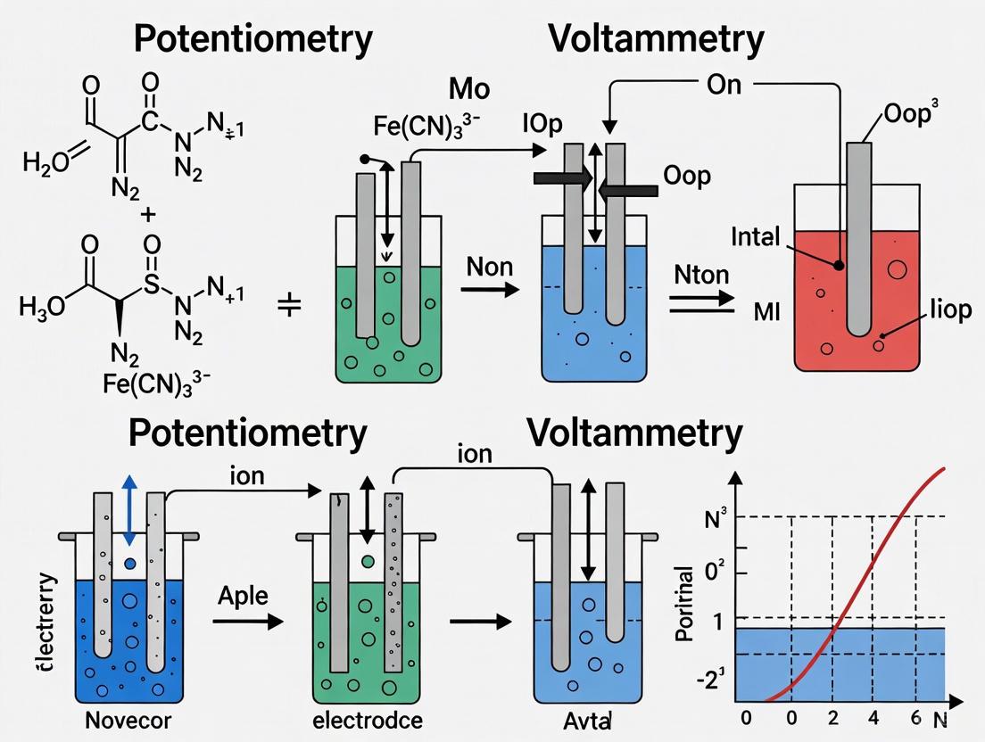
Figure 1: Technique Comparison: Potentiometry vs. Voltammetry
Comparative Framework: Potentiometry vs. Voltammetry
Fundamental Operational Differences
Understanding the distinction between potentiometry and voltammetry is essential for selecting the appropriate analytical method for drug development applications. While both are electrochemical techniques, their operational principles and applications differ significantly [4]:
Potentiometry is a passive technique that measures the potential difference between two electrodes at zero current. This potential develops spontaneously due to the difference in ion activities across a selective membrane and is governed by the Nernst equation. The method is non-destructive and provides direct measurement of ion activities without altering the sample composition significantly.
Voltammetry is an active technique that applies a controlled, varying potential to the working electrode and measures the resulting current. This current results from redox reactions occurring at the electrode surface and is proportional to the concentration of electroactive species. Voltammetric techniques are dynamic and can provide information about reaction kinetics, mechanisms, and diffusion coefficients.
Table 2: Comparative Analysis of Potentiometric and Voltammetric Techniques
| Parameter | Potentiometry | Voltammetry |
|---|---|---|
| Measured Quantity | Potential difference at zero current | Current as function of applied potential |
| Governing Equation | Nernst equation | Current-voltage relationships |
| Excitation Signal | None (zero current) | Varied potential (sweep, pulse, step) |
| Primary Application | Ion activity/concentration measurement | Redox behavior, trace analysis, kinetics |
| Sensitivity | ~10⁻⁶ to 10⁻¹ M | ~10⁻¹⁰ to 10⁻⁶ M |
| Selectivity | High with ion-selective membranes | Moderate to high with modified electrodes |
| Sample Consumption | Minimal | Moderate to high |
| Technique Variants | Direct potentiometry, potentiometric titration | Cyclic voltammetry, differential pulse, square wave |
Information Content and Applications
The different operational principles of potentiometry and voltammetry yield complementary information about analytical samples:
Potentiometric applications include:
- pH measurement using glass electrodes
- Ion-selective electrodes for sodium (Na⁺), potassium (K⁺), calcium (Ca²⁺), fluoride (F⁻), and chloride (Cl⁻) in clinical labs for electrolyte analysis
- Environmental monitoring for water quality assessment
- Potentiometric titrations where the endpoint is determined by a sharp change in potential [4]
Voltammetric applications include:
- Trace metal analysis in environmental samples
- Drug quantification in pharmaceutical formulations
- Reaction mechanism studies through cyclic voltammetry
- Detection of organic compounds and heavy metals using pulsed techniques [4]
For pharmaceutical researchers, this distinction is critical when designing analytical methods. Potentiometry offers simple, direct measurement of specific ions, while voltammetry provides richer information about redox properties and reaction mechanisms of drug compounds.
Experimental Protocols and Methodologies
Potentiometric Sensor Development Protocol
The development of potentiometric sensors for pharmaceutical analysis follows a systematic approach:
Step 1: Electrode Design and Preparation
- Select appropriate ion-selective membrane composition based on the target analyte
- Incorporate ionophores, plasticizers, and polymer matrices for membrane formation
- Prepare the electrode body with internal filling solution or solid contact
Step 2: Electrode Conditioning
- Soak the newly prepared electrode in a standard solution of the target analyte
- Allow the electrode potential to stabilize typically for 24-48 hours
- Establish stable baseline potential before calibration
Step 3: Calibration Procedure
- Prepare standard solutions of the analyte across the concentration range of interest
- Measure the electrode potential in each standard solution under zero-current conditions
- Plot potential (E) versus logarithm of analyte activity (log a)
- Determine slope, linear range, and detection limit from the calibration curve
Step 4: Sample Measurement
- Measure electrode potential in unknown samples using the same conditions
- Determine analyte concentration from the calibration curve
- Use standard addition method for samples with complex matrices
Step 5: Validation and Optimization
- Evaluate selectivity coefficients against potential interfering ions
- Assess response time, reproducibility, and long-term stability
- Optimize membrane composition based on performance characteristics
This protocol has been successfully applied to the determination of anti-epileptic drugs in pharmaceutical and biological samples, demonstrating the practical utility of potentiometric methods in drug development [5].
Experimental Verification of the Nernst Equation
To experimentally verify the Nernst equation and determine key electrode parameters:
Objective: Confirm the Nernstian response of an ion-selective electrode and determine its slope, linear range, and detection limit.
Materials:
- Ion-selective electrode and appropriate reference electrode
- Standard solutions of analyte across concentration range
- High-impedance potentiometer or pH/mV meter
- Magnetic stirrer with temperature control
- Volumetric flasks and laboratory glassware
Procedure:
- Prepare standard solutions of the analyte covering at least three orders of magnitude in concentration.
- Temperature-equilibrate all solutions to 25°C ± 0.1°C.
- Immerse the electrode system in the most dilute standard and measure the potential under stirring.
- Rinse electrodes thoroughly with distilled water and proceed to the next standard in increasing concentration order.
- Record the stable potential reading for each standard solution.
- Plot E (mV) versus log(concentration) and perform linear regression.
- Calculate the experimental slope and compare with theoretical Nernstian slope (59.16/z mV/decade at 25°C).
Data Analysis:
- Experimental slope = (RT/zF) × 2.303 × 1000 mV/decade
- Correlation coefficient (r) should exceed 0.999 for ideal Nernstian response
- Linear range determined from concentrations where response remains linear
- Detection limit typically calculated as concentration where E deviates by 18/z mV from extrapolated linear region
Figure 2: Potentiometric Experimental Workflow
The Researcher's Toolkit: Essential Materials and Reagents
Successful implementation of potentiometric methods based on the Nernst equation requires specific materials and instrumentation. The following table details essential components for potentiometric research in pharmaceutical applications.
Table 3: Essential Research Reagents and Materials for Potentiometric Analysis
| Item | Specification | Function/Purpose |
|---|---|---|
| Ion-Selective Electrodes | pH electrode, cation-selective electrodes (Na⁺, K⁺, Ca²⁺), anion-selective electrodes (Cl⁻, F⁻) | Sensing element that generates potential response proportional to target ion activity |
| Reference Electrodes | Ag/AgCl, saturated calomel electrode (SCE) | Provides stable, known reference potential against which working electrode potential is measured |
| Potentiometer | High-impedance (>10¹² Ω) pH/mV meter | Measures potential difference under zero-current conditions without drawing significant current |
| Ionophores | Neutral carriers, charged carriers specific to target ions | Selective molecular recognition elements incorporated into sensor membranes |
| Polymer Matrices | PVC, polyurethane, silicone rubber | Provides structural support for ion-selective membranes |
| Plasticizers | o-NPOE, DOS, DBP | Implements membrane fluidity and governs dielectric properties |
| Ionic Additives | Lipophilic salts (e.g., KTpClPB) | Controls membrane resistivity and reduces interference |
| Standard Solutions | Certified reference materials, analytical grade salts | Used for electrode calibration and method validation |
| Buffer Solutions | pH buffers, ionic strength adjusters | Controls sample pH and maintains constant ionic background |
Advanced Applications in Pharmaceutical Research
Drug Analysis and Quality Control
Potentiometric methods based on the Nernst equation have found extensive applications in pharmaceutical analysis due to their simplicity, selectivity, and capability for direct measurement in colored or turbid samples without requiring pretreatment [6]. The successful use of developed sensors in real sample analysis has made potentiometric sensors the center of attention in pharmaceutical quality control [6].
Specific applications include:
- Active pharmaceutical ingredient (API) quantification in dosage forms
- Dissolution testing and drug release profiling
- Stability testing of pharmaceutical formulations
- Content uniformity assessment of solid dosage forms
- Ion-level monitoring in parenteral solutions
For example, potentiometric sensors have been developed for the determination of anti-epileptic drugs in pharmaceutical and biological samples, providing rapid and cost-effective alternatives to chromatographic methods [5]. These sensors offer adequate sensitivity for therapeutic drug monitoring and quality control applications.
Real Sample Analysis and Validation
The application of potentiometric sensors to real sample analysis requires careful consideration of matrix effects and potential interferents. Key validation parameters include:
- Accuracy: Typically assessed through recovery studies in real samples, with acceptable recovery rates of 95-105%
- Selectivity: Evaluated using the separate solution method or fixed interference method to determine selectivity coefficients
- Precision: Expressed as relative standard deviation (RSD) of repeated measurements
- Working concentration range: Determined from the linear portion of the calibration curve
- Detection limit: Lowest measurable concentration distinguishable from zero
Recent reviews highlight that hundreds of different potentiometric sensors have been developed and successfully applied to real sample analysis with high recovery rates [6]. This demonstrates the maturity and reliability of potentiometric methods based on the Nernst equation for pharmaceutical applications.
The Nernst equation remains the fundamental theoretical principle governing potentiometric response, providing the mathematical foundation that relates electrode potential to analyte activity or concentration. Within the comparative framework of electrochemical techniques, potentiometry's distinctive feature is its operation under zero-current conditions, directly harnessing the Nernstian relationship for quantitative analysis.
For researchers and drug development professionals, understanding this fundamental relationship is essential for leveraging potentiometric methods in pharmaceutical analysis. The technique offers distinct advantages for drug quality control, therapeutic drug monitoring, and formulation analysis, particularly when rapid, cost-effective分析方法 are required without compromising accuracy.
As electrochemical sensor technology continues to evolve, with advancements in miniaturization, materials science, and signal processing, the Nernst equation will maintain its central role in the development and application of potentiometric sensors across pharmaceutical research and development.
The universal three-electrode system is a fundamental cornerstone of modern electrochemical research, providing the precise control and measurement capabilities required to advance fields from material science to drug development. This configuration, comprising a Working Electrode, Reference Electrode, and Counter Electrode, enables researchers to isolate and study complex electrochemical phenomena with unprecedented accuracy [10]. Its development in the 1920s addressed critical limitations of the simpler two-electrode setup, primarily by separating the current-carrying and potential-sensing functions into distinct circuits [10]. Within the broader thesis of electrochemical analytical techniques, the three-electrode system serves as the physical implementation platform that bridges the theoretical principles of potentiometry and the dynamic measurements of voltammetry [4]. By providing a stable potential reference point while allowing significant current flow, this system empowers researchers to extract both quantitative concentration data and qualitative mechanistic insights across diverse experimental conditions [11] [12].
System Architecture and Theoretical Framework
The "Three-Electrode, Two-Circuit" Principle
The operational principle of the three-electrode system can be conceptualized as two separate circuits working in tandem [11]:
- Potential Control Circuit: This high-impedance pathway connects the Working Electrode and Reference Electrode, featuring a voltmeter that accurately measures the potential difference between them without drawing significant current [10] [12].
- Current Flow Circuit: This lower-impedance pathway connects the Working Electrode and Counter Electrode, featuring an ammeter that measures the current resulting from the electrochemical reaction of interest [11] [10].
This separation is crucial because it prevents the current flow from polarizing the Reference Electrode, thereby maintaining a stable potential reference throughout the experiment [10]. The electrochemical workstation (potentiostat) uses the feedback from the potential control circuit to adjust current flow through the current flow circuit, maintaining the desired potential at the Working Electrode regardless of current magnitude [12].
Diagram 1: The dual-circuit architecture of a three-electrode system.
Comparative Analysis: Two-Electrode vs. Three-Electrode Systems
The evolution from two-electrode to three-electrode systems represented a quantum leap in electrochemical measurement capabilities, particularly for research requiring precise potential control.
Table 1: Fundamental differences between two-electrode and three-electrode systems
| Parameter | Two-Electrode System | Three-Electrode System |
|---|---|---|
| Electrode Configuration | Working + Counter/Reference combined | Working, Reference, and Counter as separate electrodes |
| Potential Measurement | Measures total cell voltage between WE and CE | Measures potential difference between WE and RE only |
| Current Path | Flows between WE and CE | Flows primarily between WE and CE |
| Reference Stability | Compromised by current flow | Maintained stable (minimal current through RE) |
| IR Drop Compensation | Difficult or impossible | Possible through measurement and compensation |
| Measurement Accuracy | Lower, especially for kinetic studies | High, suitable for precise kinetic measurements |
| Typical Applications | Simple conductivity, basic battery testing | Advanced research: mechanism studies, sensor development, kinetic analysis |
The critical limitation of the two-electrode system lies in its inability to distinguish the working electrode potential from the counter electrode potential and solution resistance effects [11]. As current flows, the counter electrode polarizes, and voltage drops occur across the solution, making the true working electrode potential uncertain [10]. The three-electrode system resolves this by introducing a dedicated Reference Electrode that maintains a stable potential, enabling accurate measurement and control of the working electrode potential regardless of current magnitude or solution resistance [12].
Electrode Roles, Specifications, and Selection Criteria
Working Electrode: The Reaction Site of Interest
The Working Electrode serves as the stage where the electrochemical reaction of interest occurs, and its properties must be carefully matched to the experimental objectives [10].
- Material Selection: Common materials include glassy carbon, platinum, gold, and various forms of carbon (carbon paper, graphite) depending on the required potential window, surface properties, and chemical inertness [11].
- Surface Preparation: Reproducible surface pretreatment is essential for experimental reproducibility. Protocols may include mechanical polishing, electrochemical cleaning, or specific chemical treatments [10].
- Geometric Considerations: The electrode surface area must be well-defined and typically standardized to enable comparison between experiments [10].
Reference Electrode: The Potential Anchor
The Reference Electrode provides the stable potential benchmark against which the Working Electrode potential is controlled and measured [12].
- Fundamental Requirement: Must maintain a constant electrochemical potential with negligible current flow [12].
- Common Reference Systems:
Counter Electrode: Current Completion Element
The Counter Electrode completes the electrical circuit by providing a surface for the balancing electrochemical reaction to occur [12].
- Material Requirements: Should be chemically inert with high conductivity and sufficient surface area to avoid becoming rate-limiting [11] [10].
- Selection Considerations: Platinum and graphite are common choices, though careful selection is needed to prevent contamination in prolonged experiments [11].
Table 2: Electrode selection guide for different experimental conditions
| Electrode Type | Common Materials | Key Characteristics | Optimal Application Context |
|---|---|---|---|
| Working Electrode | Glassy carbon, Pt, Au, carbon paper, metal foams | Defined surface area, reproducible surface, chemically inert | Reaction-dependent: GCE for general electrochemistry, specialized materials for specific reactions |
| Reference Electrode | Ag/AgCl, SCE, Hg/HgO | Stable, known potential, minimal current draw | Electrolyte pH-dependent: SCE (acidic), Ag/AgCl (neutral), Hg/HgO (alkaline) |
| Counter Electrode | Pt wire/mesh, graphite rod | High conductivity, large surface area, chemical stability | Reaction-dependent: graphite preferred when Pt dissolution may contaminate system |
Experimental Methodologies and Protocols
System Setup and Electrode Preparation
Proper experimental setup begins with meticulous electrode preparation and cell configuration [11]:
Working Electrode Preparation Protocol:
- Surface Polishing: For solid electrodes like glassy carbon, sequentially polish with alumina slurry of decreasing particle size (1.0, 0.3, and 0.05 µm) on a microcloth pad
- Sonication: Remove adsorbed particles by sonicating in purified water for 1-2 minutes
- Electrochemical Activation: Perform cyclic voltammetry in a clean electrolyte until stable response is achieved
- Catalyst Deposition (if applicable): Prepare catalyst ink by dispersing catalyst material in appropriate solvent with binder
- Drop-casting: Apply controlled volume of ink to electrode surface and allow to dry
Electrochemical Cell Assembly:
- Electrode Placement: Position Reference Electrode close to Working Electrode surface to minimize uncompensated solution resistance
- Counter Electrode Positioning: Place Counter Electrode symmetrically to ensure uniform current distribution
- Gas Purging: For reactions involving gases, saturate electrolyte with appropriate gas before measurements
Core Electrochemical Techniques: Operational Protocols
Cyclic Voltammetry Methodology
Cyclic Voltammetry is a powerful technique for studying electrode reaction mechanisms and kinetics [4].
Standard Protocol:
- Initial Parameters: Set starting potential where no faradaic reaction occurs
- Vertex Potentials: Define reversal potentials based on redox processes of interest
- Scan Rate Selection: Typically 1-1000 mV/s, depending on system kinetics
- Cycle Definition: Specify number of cycles to assess stability
Data Interpretation:
- Reversible systems show symmetrical reduction and oxidation peaks
- Peak separation (ΔEp) provides information about electron transfer kinetics
- Peak current proportionality to square root of scan rate indicates diffusion control
Linear Sweep Voltammetry for Reaction Analysis
LSV is particularly valuable for quantifying electrocatalytic activity, such as in hydrogen evolution or oxygen evolution reactions [11].
HER/OER Testing Protocol:
- Potential Range Selection: Set based on thermodynamic considerations and reference electrode
- Scan Rate: Use slow scan rates (typically 1-5 mV/s) for quasi-steady-state measurements
- IR Compensation: Apply appropriate compensation based on electrochemical impedance spectroscopy data
- Gas Saturation: Purge electrolyte with appropriate gas before measurements
Diagram 2: Standard workflow for three-electrode system experimentation.
The Scientist's Toolkit: Essential Research Reagents and Materials
Successful implementation of three-electrode systems requires careful selection of consumables and materials tailored to specific experimental needs.
Table 3: Essential research reagents and materials for three-electrode experiments
| Category | Specific Items | Function/Purpose | Selection Considerations |
|---|---|---|---|
| Electrode Materials | Glassy carbon electrodes, platinum wire, graphite rods, carbon paper, metal foams | Provide platforms for electrochemical reactions | Choose based on potential window, chemical stability, and catalytic properties |
| Reference Systems | Ag/AgCl pellets, SCE components, Hg/HgO elements | Establish stable potential reference | Select based on electrolyte compatibility and required potential range |
| Electrolytes | Sulfuric acid, potassium hydroxide, phosphate buffers, lithium perchlorate | Provide ionic conductivity and define electrochemical environment | Consider pH requirements, potential window, and compatibility with analytes |
| Cell Components | Glass electrolytic cells, O-rings, electrode holders, gas dispersion tubes | Contain experiment and maintain proper electrode positioning | Choose materials compatible with electrolytes (glass, PTFE preferred) |
| Preparation Supplies | Alumina polishing powders, Nafion solution, isopropanol, ultrasonication baths | Enable electrode preparation and catalyst deposition | Use high-purity materials to prevent contamination |
| Specialty Chemicals | Conductive carbon blacks, specific catalyst materials, redox mediators | Enhance conductivity or facilitate specific reactions | Select based on mechanism under investigation |
Advanced Applications and Research Context
Contextualizing Potentiometry vs. Voltammetry Research
Within electrochemical research methodologies, the three-electrode system enables the distinct capabilities of both potentiometry and voltammetry:
Potentiometric Applications:
- Zero-current potential measurements for concentration determination [4]
- Ion-selective electrode measurements following Nernst equation principles [4]
- Stable reference potential enables precise measurement of equilibrium potentials [12]
Voltammetric Applications:
- Dynamic current measurement during controlled potential sweeps [4]
- Investigation of electron transfer kinetics and reaction mechanisms [13]
- Trace analysis through pulsed techniques (DPV, SWV) [4]
The three-electrode system is particularly crucial for voltammetric studies where accurate potential control is essential for meaningful results, especially in systems with significant current flow [11].
Case Study: Heavy Metal Detection in Environmental Samples
Research demonstrates the application of three-electrode systems in detecting Hg²⁺ ions using a WS₂-WO₃/P2ABT nanocomposite sensor [14]. The system employed:
- Working Electrode: Nanocomposite-modified electrode
- Reference Electrode: Calomel electrode
- Counter Electrode: Graphite electrode
This configuration enabled both cyclic voltammetry measurements showing increasing current response with Hg²⁺ concentration, and potentiometric detection with a Nernstian slope of 33.0 mV/decade [14]. The study highlights how proper three-electrode configuration facilitates multiple measurement techniques on the same system, providing complementary data for robust analysis.
Troubleshooting and Optimization Strategies
Common Experimental Challenges and Solutions
- Unstable Potentials: Often caused by clogged reference electrode frits or insufficient chloride concentration in reference systems
- Noisy Current Signals: Frequently results from poor shielding, ground loops, or insufficient filtering
- Non-reproducible Results: Commonly stems from inconsistent working electrode pretreatment or contamination
- Uncompensated Resistance Effects: Mitigated by proper reference electrode placement and appropriate IR compensation techniques [11]
Optimization Guidelines for Specific Applications
High-Precision Kinetic Studies:
- Minimize uncompensated resistance through careful cell design
- Use fast-response reference electrodes
- Apply appropriate IR compensation strategies [11]
Trace Analysis Applications:
- Implement electromagnetic shielding
- Utilize differential pulse or square wave voltammetry
- Employ background subtraction techniques [4]
Extended Duration Experiments:
- Select counter electrode materials that won't contaminate system
- Monitor reference electrode stability throughout experiment
- Consider use of pseudo-reference electrodes with periodic calibration [10]
The universal three-electrode system remains an indispensable platform for advanced electrochemical research, providing the necessary architecture to discriminate between potentiometric and voltammetric approaches while delivering the precision required for modern analytical applications. Its continued evolution supports increasingly sophisticated investigations into reaction mechanisms, materials properties, and analytical detection schemes across scientific disciplines. By mastering the principles, configurations, and methodologies outlined in this guide, researchers can leverage the full potential of this fundamental electrochemical tool to advance their scientific objectives.
In the realm of electrochemical analysis, potentiometry stands as a fundamental technique distinguished by its measurement of electrical potential under conditions of zero or negligible current flow. This method contrasts sharply with voltammetry, which measures current as a function of an applied potential, requiring a three-electrode system for precise control. The distinct advantage of potentiometry lies in its simplicity, cost-effectiveness, and ability to provide direct information about ion activities in solution [4] [1]. At the heart of every potentiometric measurement lies the indicator electrode, a device whose potential responds selectively to the activity of a specific ion in solution. This technical guide focuses on two cornerstone components of modern potentiometry: the classic glass membrane electrode and the broader family of ion-selective electrodes (ISEs). These sensors have become indispensable across chemical, biological, pharmaceutical, and environmental disciplines due to their exceptional selectivity, sensitivity, and adaptability [4] [15]. Understanding their operating principles, construction, and applications is crucial for researchers leveraging potentiometric methods, particularly when compared to the dynamic measurements of voltammetry.
Theoretical Foundations: The Potentiometric Principle
The fundamental principle of potentiometry is governed by the Nernst equation, which describes the relationship between the measured electrochemical potential of an electrode and the activity (effective concentration) of an ion in solution. For an ion, ( A ), with charge ( z ), the potential of an ideal indicator electrode, ( E ), is given by:
[ E = \text{constant} + \frac{RT}{zF} \ln a_A ]
Where ( R ) is the universal gas constant, ( T ) is the temperature in Kelvin, ( F ) is the Faraday constant, and ( a_A ) is the activity of ion ( A ) [16] [17]. The "constant" term includes the standard potential of the electrode and the potential of the reference electrode. At a temperature of 25°C, and converting from natural logarithm to base-10 logarithm, the equation simplifies to a more practical form:
[ E = \text{constant} + \frac{0.05916}{z} \log a_A ]
This Nernstian response produces a linear plot of ( E ) versus ( \log a_A ), with a slope of ( 59.16/z ) mV per decade, which serves as a benchmark for evaluating electrode performance [16] [18]. Potentiometric measurements are performed using an electrochemical cell comprising an indicator electrode and a reference electrode with a stable, fixed potential. The overall cell potential is measured with a high-impedance voltmeter to ensure current flow remains virtually zero, preserving solution composition [18].
The Glass Membrane Electrode
Composition and Structure
The glass membrane electrode represents the oldest and most well-known type of ion-selective electrode. While most famously used for pH measurement, specialized glass formulations can confer selectivity for other single-charged cations like sodium (Na⁺) and silver (Ag⁺) [16] [19]. The core component is a thin, ion-exchange glass membrane, typically composed of silicate or chalcogenide glass, which is fused to the end of an inert glass or plastic body. The membrane is an amorphous, rigid, and hygroscopic material [16] [19]. The internal structure of a typical pH glass electrode consists of several layers:
- Internal Solution: A solution of constant pH and activity, typically a buffered chloride solution.
- Internal Reference Electrode: Most commonly a silver/silver chloride (Ag/AgCl) wire immersed in the internal solution.
- Glass Membrane: A hydrated glass layer that develops on both the inner and outer surfaces of the membrane after immersion in an aqueous solution. This hydrated gel layer is critical for the electrode's function [16].
Response Mechanism and Selectivity
The potential across the glass membrane develops due to an ion-exchange process within the hydrated gel layers. For a pH electrode, hydrogen ions (H⁺) from the solution interact with binding sites on the surface of the hydrated glass. The key to the membrane's function is that the glass composition is tailored so that H⁺ binds more strongly to these sites than any other cation. This differential binding affinity establishes a boundary potential at the interface between the sample solution and the membrane, as well as at the interface between the internal solution and the membrane [16]. The overall membrane potential, ( E{\text{mem}} ), depends on the difference in H⁺ activity between the sample (( a{\text{H⁺, samp}} )) and the internal solution (( a_{\text{H⁺, int}} )):
[ E{\text{mem}} = E{\text{asym}} - \frac{RT}{F} \ln \frac{a{\text{H⁺, int}}}{a{\text{H⁺, samp}}} ]
Where ( E_{\text{asym}} ) is an asymmetry potential that accounts for minor differences between the two membrane surfaces [16]. Since the activity of H⁺ in the internal solution is fixed, the measured potential is directly proportional to the pH of the sample. The selectivity of the glass membrane is intrinsically tied to its chemical composition. For instance, a common pH-sensitive glass contains SiO₂, Na₂O, and CaO. The selectivity for H⁺ over Na⁺ is high but not infinite; in highly alkaline solutions (high Na⁺, low H⁺), the electrode may exhibit a slight response to sodium ions, known as the "alkaline error" [19].
Ion-Selective Electrodes (ISEs)
General Principles and Classification
Ion-selective electrodes are potentiometric sensors that incorporate a specialized membrane capable of selectively binding a target ion. The core component is the ion-selective membrane (ISM), which separates the sample solution from the internal electrode assembly. As with the glass electrode, the membrane potential develops due to the selective partitioning of the target ion between the sample and the membrane phase, following a Nernstian relationship [16] [19]. ISEs are broadly classified based on the nature and composition of their membrane, each offering distinct advantages and suited for different analytical challenges. The table below summarizes the primary types of ISE membranes.
Table 1: Classification of Ion-Selective Electrode Membranes
| Membrane Type | Composition | Target Ions | Key Features |
|---|---|---|---|
| Glass Membrane [19] | Silicate or chalcogenide glass | H⁺, Na⁺, Ag⁺ | Excellent chemical durability, good selectivity, well-established for pH |
| Crystalline Membrane [16] [19] | Mono- or polycrystalline solids | F⁻, Cl⁻, Br⁻, I⁻, CN⁻, S²⁻, Cd²⁺, Pb²⁺ | High selectivity (only ions introducing into crystal lattice interfere), robust |
| Ion-Exchange Resin (Polymeric) Membrane [20] [19] | PVC or other polymers plasticized with ion exchanger/ionophore | Wide variety (K⁺, Ca²⁺, NH₄⁺, NO₃⁻, drug cations/anions) | Highly versatile, wide array of ionophores available, most widespread type |
| Enzyme Electrode [19] | Enzyme layer over a standard ISE | Substrates like glucose, urea, etc. | "Double reaction" mechanism; enzyme produces a detectable ion (e.g., H⁺) |
Response Mechanism of Polymeric Membrane ISEs
The functioning of a modern polymeric ISE, common in pharmaceutical and research applications, involves a sophisticated interplay of components. The membrane is typically composed of polyvinyl chloride (PVC) plasticized to create a viscous organic liquid phase, in which several key components are dissolved [20]:
- Ionophore: A neutral or charged carrier molecule that selectively binds to the target ion. Its selectivity dictates the electrode's performance.
- Ionic Additive: A lipophilic salt (e.g., potassium tetrakis(4-chlorophenyl) borate, KTpClPB) to control the membrane's ionic properties and improve selectivity and detection limit [20] [15].
- Plasticizer: Provides the liquid matrix and can also influence the membrane's dielectric constant and ionophore solubility.
The potential is generated as the target ion, for instance, a drug cation (( C^+ )), partitions from the aqueous sample into the organic membrane phase, facilitated by selective complexation with the ionophore. This creates a phase boundary potential at the sample-membrane interface. The ionic additive ensures the membrane remains conductive and helps establish a stable potential [20] [15].
Electrode Design: From Liquid-Contact to Solid-Contact
The physical design of ISEs has evolved significantly, leading to improved stability and miniaturization.
- Liquid-Contact ISEs: This traditional design features an internal filling solution containing the target ion at a fixed activity. An internal reference electrode (e.g., Ag/AgCl) is immersed in this solution. While reliable, these electrodes can suffer from evaporation or leakage of the internal solution, limiting their shelf-life and making miniaturization difficult [1] [15].
- Solid-Contact ISEs (SC-ISEs): This advanced design eliminates the internal solution, replacing it with a solid conductive layer that acts as an ion-to-electron transducer. This layer is coated with the ion-selective membrane. SC-ISEs are mechanically robust, easier to miniaturize, and ideal for disposable sensors or point-of-care devices [1] [15]. The ion-to-electron transduction in the solid contact layer can occur via two primary mechanisms:
- Redox Capacitance: Using conducting polymers (e.g., PEDOT, polyaniline) that undergo reversible oxidation/reduction, translating ionic signal to an electronic signal [1].
- Electric-Double-Layer Capacitance: Using carbon-based nanomaterials (e.g., graphene, carbon nanotubes) or composite materials that form a capacitive interface at the ISM/transducer boundary [1].
The following diagram illustrates the architecture and charge-transfer mechanism of a solid-contact ISE.
Experimental Protocols in Pharmaceutical Analysis
Fabrication of a Solid-Contact ISE for Drug Analysis
The development of ISEs for monitoring drug release, as demonstrated for propranolol and lidocaine, involves a multi-step fabrication and testing protocol [20].
1. Membrane Cocktail Preparation:
- Composition: Combine 33% PVC (polymer matrix), 66% 2-nitrophenyl octyl ether (NPOE, plasticizer), and 1% potassium tetrakis(4-chlorophenyl) borate (KTpClPB, ionic additive) by weight [20].
- Dissolution: Dissolve this "dry" mixture in an organic solvent, typically tetrahydrofuran (THF), to create a "membrane cocktail" (e.g., 20% w/w dry part in THF) [20].
2. Solid-Contact Electrode Assembly:
- A conductive substrate (e.g., a rolled carbon cloth) is mounted inside an electrode body.
- The membrane cocktail is drop-cast onto the substrate surface in multiple aliquots (e.g., 450 µL total, in 100 µL portions every 30 minutes) to allow slow, even evaporation of the solvent and form a homogeneous membrane [20].
- The assembled electrode is conditioned by soaking in a solution of the target drug (e.g., 1.0 × 10⁻³ M propranolol HCl in 10⁻² M HCl, pH 2.0) for 24-48 hours to establish a stable potential [20].
3. Potentiometric Measurement and Drug Release Study:
- The conditioned ISE and a separate reference electrode (e.g., Ag/AgCl) are immersed in a stirred dissolution vessel containing the release medium.
- A drug-loaded dosage form (e.g., a polymer film or a drug-coated porous cellulose substrate) is introduced.
- The potential is recorded continuously (e.g., every 10 seconds) using a high-impedance data acquisition system.
- The potential values are converted to concentration values using a pre-established calibration curve, allowing the construction of a real-time drug release profile [20].
The Scientist's Toolkit: Essential Research Reagents
The following table details key materials and reagents required for fabricating and applying ISEs in a research context, based on the cited experimental work.
Table 2: Essential Research Reagents for ISE Fabrication and Analysis
| Reagent/Material | Function | Example from Literature |
|---|---|---|
| Polyvinyl Chloride (PVC) [20] | Serves as the polymeric matrix for the ion-selective membrane, providing structural integrity. | High molecular weight PVC (Fluka Selectophore) [20]. |
| Plasticizer [20] | Imparts plasticity to the PVC membrane, creating a liquid-like phase for ion diffusion; can influence dielectric constant. | 2-Nitrophenyl octyl ether (NPOE) [20]. |
| Ionophore (Ion Carrier) [15] | The key selective element; specifically complexes with the target ion, dictating sensor selectivity. | Valinomycin for potassium; custom ionophores for drugs [19] [15]. |
| Ionic Additive (Lipophilic Salt) [20] | Improves membrane conductivity, reduces membrane resistance, and lowers the detection limit by minimizing co-ion interference. | Potassium tetrakis(4-chlorophenyl) borate (KTpClPB) [20]. |
| Solid-Contact Transducer Material [1] [15] | Facilitates ion-to-electron transduction in solid-contact ISEs; provides high capacitance and stable potential. | Conducting polymers (PEDOT), carbon cloth, carbon nanotubes, graphene [20] [1]. |
| Tetrahydrofuran (THF) [20] | Volatile organic solvent used to dissolve membrane components for drop-casting. | Tetrahydrofuran (Fluka Selectophore) [20]. |
| Reference Electrode [4] [20] | Provides a stable, known reference potential against which the ISE potential is measured. | Ag/AgCl/3 M KCl reference electrode (e.g., Metrohm) [20]. |
Comparative Analysis with Voltammetry and Future Outlook
Potentiometry vs. Voltammetry: A Technical Comparison
While both are electrochemical techniques, potentiometry and voltammetry differ fundamentally in their operational principles and the information they provide, making them complementary tools.
Table 3: Core Differences Between Potentiometry and Voltammetry
| Parameter | Potentiometry | Voltammetry |
|---|---|---|
| Measured Quantity | Potential (Voltage) at zero current [4] [1] | Current as a function of applied potential [4] |
| Electrode System | Two-electrode system (Indicator + Reference) [18] | Three-electrode system (Working, Reference, Counter) [4] [1] |
| Fundamental Equation | Nernst Equation [16] [18] | Butler-Volmer Equation (and others) [4] |
| Output | Ion activity (concentration) [16] | Redox behavior, kinetics, concentration [4] |
| Selectivity Source | Selective membrane/ionophore [16] [19] | Applied potential and electrode surface [4] |
| Power Consumption | Very low (measures at equilibrium) [1] | Higher (applies potential to drive current) [1] |
Emerging Trends and Future Directions
The field of potentiometric sensors is rapidly advancing, driven by new materials and technologies. Key trends include:
- Miniaturization and Wearable Sensors: SC-ISEs are ideal for integration into wearable devices for non-invasive health monitoring (e.g., epidermal patches, smart watches) that can track electrolytes or drug levels in real-time using wireless protocols like Bluetooth [1] [15].
- Advanced Transducer Materials: Research is focused on nanocomposite materials (e.g., MoS₂ nanoflowers with Fe₃O₄, tubular gold nanoparticles) that offer ultra-high capacitance and signal stability, pushing the limits of detection and reproducibility [1].
- Novel Manufacturing Techniques: Additive manufacturing (3D printing) and paper-based microfluidic devices are being explored to create low-cost, disposable, and complex sensor geometries for point-of-care testing [1].
- Expanded Pharmaceutical Applications: ISEs are increasingly used for content uniformity testing, dissolution profiling of immediate-release dosage forms, and therapeutic drug monitoring (TDM) due to their ability to provide continuous, real-time data without sample pretreatment [20] [15].
In conclusion, glass membranes and ion-selective electrodes represent a powerful and versatile class of indicator electrodes that are central to the potentiometric technique. Their continued evolution, particularly toward solid-contact designs and miniaturized formats, ensures they will remain at the forefront of analytical science, offering researchers and drug development professionals robust tools for precise ionic measurement.
Within the broader research context comparing potentiometry and voltammetry, understanding the core components of voltammetric systems is paramount. While potentiometry measures the potential at zero current to determine ion activity, voltammetry is a dynamic technique that applies a controlled potential to a working electrode and measures the resulting current, providing rich information about the identity and concentration of electroactive species [21]. The working electrode (WE) is the central component in any voltammetric system, serving as the stage where the electrochemical reaction of interest occurs [22]. Its material composition critically influences the sensitivity, selectivity, and scope of an analysis by defining the potential window, electron transfer kinetics, and susceptibility to fouling.
This guide provides an in-depth examination of the four most historically and practically significant working electrode materials: mercury, gold, platinum, and glassy carbon. Each material offers a unique set of electrochemical properties that make it suitable for specific applications, from the detection of heavy metals to the analysis of pharmaceutical compounds. By presenting a detailed comparison of their characteristics, experimental protocols for their use, and their modern applications, this document aims to serve as an essential resource for researchers and scientists in selecting the optimal working electrode for their analytical challenges.
Core Principles of the Working Electrode
In a standard three-electrode voltammetric cell, the working electrode's potential is precisely controlled relative to a stable reference electrode (e.g., Ag/AgCl or SCE), while the current is measured between the WE and an auxiliary (or counter) electrode [21]. The primary function of the WE is to facilitate the transfer of electrons to or from analyte molecules in solution. The choice of WE material directly determines several key experimental parameters:
- Potential Window: The range of potentials over which the electrode is stable and the background current from electrolyte decomposition is minimal. This window dictates which redox couples can be studied [23] [24].
- Electron Transfer Kinetics: The rate at which electrons are exchanged between the electrode and the analyte, which affects the sharpness and reversibility of the voltammetric response.
- Surface Renewability and Reproducibility: The ease with which a fresh, reproducible electrode surface can be generated, which is crucial for quantitative analysis.
- Fouling Resistance: The electrode's susceptibility to deactivation by adsorption of reactants or products.
An ideal polarizable electrode behaves like a capacitor, allowing its potential to be varied without significant Faradaic current flow; the potential range where this occurs is known as the "potential window" [24]. The presence of electroactive species adds a potential-dependent Faradaic resistance and a Warburg impedance related to diffusion into the equivalent circuit [24].
Material-Specific Analysis
Mercury Electrodes
Merits and Limitations: Mercury electrodes, including the Dropping Mercury Electrode (DME) and Hanging Mercury Drop Electrode (HMDE), are characterized by their exceptionally high overpotential for hydrogen evolution [21]. This property provides an extensive cathodic (reductive) potential window, allowing access to the reduction of metal ions like Zn²⁺ that would be obscured by solvent breakdown at other electrodes [23] [25]. A freshly renewable, atomically smooth surface is easily produced, ensuring excellent reproducibility [21] [24]. A unique advantage is mercury's ability to form amalgams with many metals, which is exploited in preconcentration techniques like Anodic Stripping Voltammetry (ASV) [23]. However, mercury's limited anodic window due to its own oxidation and its significant toxicity have reduced its prevalence in modern laboratories [23] [24].
Applications: Mercury electrodes are the traditional choice for the determination of heavy metal ions (e.g., Pb, Cd, Tl, In, Zn) via ASV [24]. Their renewable surface is also beneficial for studying electrochemical reduction mechanisms in organic chemistry.
Modern Trends: To mitigate toxicity concerns while retaining analytical benefits, mercury is often used as a thin film plated onto a solid electrode substrate like glassy carbon [23] [21].
Gold Electrodes
Merits and Limitations: Gold electrodes offer a wider cathodic potential range than platinum and lack the distinct hydrogen adsorption/desorption waves seen on platinum, resulting in a cleaner background in certain regions [25] [24]. A principal merit of gold is its well-established surface chemistry, particularly its ability to form robust self-assembled monolayers (SAMs) with thiol-containing molecules, enabling the creation of highly specific chemical sensors [23]. A key limitation is its tendency to oxidize at relatively modest anodic potentials, especially in the presence of chloride ions, which restricts its anodic window [23] [24].
Applications: Gold is widely used for the detection of thiols and in the construction of biosensors through SAM-based modifications [25]. Recent research focuses on nanostructured gold and its alloys for enhanced sensing. For instance, a 2025 study detailed a gold-mercury-platinum (AuHgPt) nanoalloy for the light-enhanced electrochemical detection of hydrogen peroxide, leveraging the localized surface plasmon resonance (LSPR) effect of gold nanoparticles [26]. Another study developed a gold particle-modified glassy carbon electrode for monitoring the drug dipyrone [27].
Platinum Electrodes
Merits and Limitations: Platinum is a favored electrode material due to its excellent electrochemical inertness and ease of fabrication into various forms (wire, disk, plate) [23]. It exhibits high overpotential for oxygen evolution, making it suitable for anodic studies in organic and inorganic chemistry [25]. Its most significant drawback is its low hydrogen overpotential, which limits its useful cathodic range in aqueous solutions as hydrogen evolution occurs at fairly modest negative potentials (E = -0.059 × pH) [23]. Platinum surfaces are also prone to contamination and can require activation cycles.
Applications: Platinum is a conventional electrode for detecting hydrogen peroxide and various oxides [25]. It is also extensively used in electrocatalysis research (e.g., for fuel cells) and for the study of oxidative reactions where a wide anodic window is required.
Glassy Carbon Electrodes
Merits and Limitations: Glassy carbon (GC) is a sp²-bonded carbon material with a dense, impermeable, and hard "vitreous" structure [28] [24]. It boasts a wide potential window in both anodic and cathodic directions, good chemical inertness, and a relatively low cost [23] [28]. It is considered chemically stable despite relatively large overpotentials for oxygen and hydrogen evolution [25]. A limitation is that the quality and performance of glassy carbon can vary significantly between sources and batches. It is also difficult to machine and requires proper polishing to maintain performance [23].
Applications: Glassy carbon is arguably the most versatile working electrode. It serves as the foundational substrate for a vast array of chemically modified electrodes. Its applications span the detection of neurotransmitters, pharmaceutical compounds (e.g., antidepressants), environmental pollutants, and heavy metals [28]. A 2025 review highlighted its prominent role in the voltammetric sensing of numerous antidepressant drugs due to its excellent properties [28].
Table 1: Comparative Analysis of Common Working Electrode Materials
| Material | Key Advantages | Key Limitations | Representative Applications |
|---|---|---|---|
| Mercury | High H⁺ overpotential (wide cathodic window); Renewable, smooth surface; Forms amalgams [23] [21] | Narrow anodic window; High toxicity [23] | Anodic Stripping Voltammetry of heavy metals (Pb, Cd, Zn) [24] |
| Gold | Wide cathodic window; No H-adsorption waves; Ideal for thiol SAMs [23] [25] [24] | Limited anodic window due to oxidation [23] | Thiol detection; Biosensors; AuHgPt nanoalloy for H₂O₂ sensing [26] [25] |
| Platinum | Electrochemically inert; High O₂ overpotential (good anodic window); Various geometries [23] [25] | Low H₂ overpotential (limited cathodic window); Expensive; Surface contamination [23] | H₂O₂ detection; Electrocatalysis (fuel cells); Organic oxidations [25] |
| Glassy Carbon | Wide potential window; Chemically inert; Good for modifications [23] [28] [25] | Quality varies; Hard to machine [23] | Drug analysis (e.g., antidepressants); Substrate for modified electrodes [28] |
Experimental Protocols and Methodologies
Electrode Polishing and Maintenance
A pristine, reproducible surface is critical for obtaining reliable and reproducible voltammetric data. Solid electrodes require periodic polishing to remove adsorbed contaminants and refresh the electroactive surface [29].
General Polishing Protocol for Glassy Carbon, Platinum, and Gold:
- Initial Rinse: Rinse the electrode surface with distilled water, followed by methanol, and then wipe dry with a clean lab tissue [29].
- Polishing Slurry: On a flat, hard surface covered with a specialized polishing cloth (e.g., microcloth), apply a slurry of an abrasive alumina (e.g., 0.3-1.0 µm diameter) in distilled water [29].
- Polishing Motion: Place the electrode face down on the pad and polish using a firm, smooth figure-eight or circular motion. Apply even pressure and periodically rotate the electrode 90° to ensure uniform wear. Polish for 1-2 minutes [29].
- Rinsing and Sonication: Rinse the electrode thoroughly with distilled water to remove all abrasive particles. For a deeper clean, sonicate the electrode in distilled water or methanol for up to 5 minutes in a low-power ultrasonic bath to dislodge trapped particles [29].
- Final Rinse: Rinse again with distilled water and then with methanol, and dry gently [29].
Special Considerations:
- Platinum and Native Gold: These may require a two-step polishing process, starting with a fine diamond slurry (e.g., 1 µm) on a nylon pad, followed by alumina on a microcloth pad to achieve a mirror finish [29].
- Handling: Never touch the polished electrode surface with fingers or place it on an abrasive surface [29].
Protocol for Sensor Fabrication: Gold-Mercury-Platinum Nanoalloy
A 2025 study presented a protocol for creating a light-enhanced H₂O₂ sensor, illustrating modern nanomaterial modification techniques [26].
- Substrate Preparation: Clean ITO glass by immersion in piranha solution for 30 min, followed by ultrasonic cleaning in water and ethanol.
- Gold Nanoparticle Deposition: Using a standard three-electrode system (ITO as working electrode, Pt counter, SCE reference), electrodeposit Au nanoparticles onto the ITO from a solution of 24 mM HAuCl₄ and 0.1 M KCl via cyclic voltammetry between 0.2 V and -1.0 V.
- Amalgam Formation: Deposit mercury onto the Au/ITO electrode by chronoamperometry at -0.3 V in a solution containing Hg(II) (1.6 mg/mL) and 0.1 M KCl, forming an AuHg amalgam.
- Galvanic Replacement: Immerse the AuHg-modified electrode in a 19 mM H₂PtCl₆ solution for 12 hours. During this period, a galvanic replacement reaction occurs:
3 Hg + [PtCl6]2− → Pt + Hg2+ + Hg2Cl2 + 4 Cl−, forming the final AuHgPt nanoalloy. - Sensor Evaluation: The modified electrode's performance for H₂O₂ detection is evaluated using chronoamperometry and cyclic voltammetry in a phosphate buffer (pH 7.4), with and without light illumination to characterize the LSPR enhancement effect [26].
Workflow for Electrode Selection and Experimentation
The following diagram outlines the logical decision-making process for selecting and preparing a working electrode for a voltammetric experiment.
Electrode Selection and Preparation Workflow
The Scientist's Toolkit: Essential Reagents and Materials
Table 2: Key Research Reagents and Materials for Voltammetry
| Item | Function / Application |
|---|---|
| Alumina Polishing Slurry (e.g., 0.05, 0.3, 1.0 µm) | Abrasive for resurfacing and cleaning solid electrodes (GC, Pt, Au) to a mirror finish [29]. |
| Diamond Polishing Slurry (e.g., 1, 3, 6 µm) | For initial or fine polishing of noble metal electrodes (Pt, Au) [29]. |
| Microfiber Polishing Pads | Soft, velvety pads used with alumina slurry for final polishing [29]. |
| Nylon Polishing Pads | Tightly woven pads used with diamond slurry for polishing noble metals [29]. |
| Supporting Electrolyte (e.g., KCl, Phosphate Buffer) | Carries current and minimizes solution resistance; defines pH environment [26]. |
| Potentiostat | Instrument that controls potential between WE and RE, and measures current between WE and CE [21]. |
| Redox Probes (e.g., Ferri/Ferrocyanide) | Standard solutions for validating electrode performance and active surface area. |
| Thiol Compounds (e.g., alkanethiols) | Used for creating self-assembled monolayers (SAMs) on gold surfaces for sensor fabrication [23]. |
| Metal Salt Solutions (e.g., HAuCl₄, H₂PtCl₆) | Precursors for electrodeposition of metal nanoparticles or formation of modified electrodes [26]. |
The selection of an appropriate working electrode material is a foundational decision in the design of any voltammetric experiment, directly determining its potential feasibility and analytical performance. As detailed in this guide, the classic quartet of mercury, gold, platinum, and glassy carbon provides a versatile toolkit, with each material offering a distinct combination of advantages and constraints. Mercury remains unparalleled for reductive analysis, gold for surface engineering, platinum for anodic studies and catalysis, and glassy carbon for general-purpose versatility and as a substrate for modified electrodes.
The ongoing evolution in this field is characterized by the development of advanced nanomaterials and composites, such as the AuHgPt nanoalloy, which aim to synergistically enhance sensitivity and specificity [26]. Furthermore, the integration of physical phenomena like LSPR with electrochemistry points to a future of increasingly sophisticated and powerful sensing platforms. For the researcher navigating the fundamentals of potentiometry versus voltammetry, this comparative analysis of working electrodes underscores a core principle: voltammetry's power lies not only in its dynamic measurement of current but also in the profound ability to tailor the interface where the critical chemistry occurs.
The field of electroanalytical chemistry is broadly divided into two principal methodologies: potentiometry and voltammetry. Potentiometry is a static, zero-current technique that measures the potential (electromotive force) of an electrochemical cell under conditions of thermodynamic equilibrium to determine analyte activity or concentration [4] [30]. In contrast, voltammetry encompasses a group of dynamic techniques where the current flowing through an electrochemical cell is measured as a function of an applied potential that is actively varied over time [31] [30]. This active application of potential induces redox reactions, causing a change in the concentration of electroactive species at the electrode surface and generating a measurable faradaic current [32]. The evolution from classical polarography to modern voltammetric techniques represents a paradigm shift in analytical capabilities, driven by advances in electronics, electrode materials, and theoretical understanding. This progression has fundamentally enhanced the sensitivity, selectivity, and application range of dynamic electroanalysis, cementing its role as an indispensable tool in modern chemical research, pharmaceutical development, and environmental monitoring.
The Birth of Polarography: Heyrovský's Legacy
The history of modern voltammetry begins with the pioneering work of Czech chemist Jaroslav Heyrovský, who invented polarography in 1922 [32]. Heyrovský's fundamental contribution was the development and application of the dropping mercury electrode (DME) as a working electrode, a innovation for which he was awarded the Nobel Prize in Chemistry in 1959 [30] [32]. The DME offered unique advantages: its renewable surface eliminated passivation and memory effects, its high hydrogen overvoltage provided a wide negative potential window, and it allowed for the facile analysis of metal ions that could form amalgams with mercury [32].
In classical direct current (DC) polarography, a linearly increasing potential is applied to the DME versus a reference electrode, and the resulting current is measured [30]. The resulting polarogram displays characteristic sigmoidal waves, where each plateau corresponds to the reduction or oxidation of a specific electroactive species in solution. The key quantitative parameters are the half-wave potential (E₁/₂), which is characteristic of the analyte and provides qualitative identification, and the limiting current (iₗ), which is proportional to analyte concentration according to the Ilkovič equation describing diffusion to a expanding mercury drop [30].
Despite its revolutionary impact, classical DC polarography suffered from significant limitations. The technique exhibited relatively poor sensitivity, with detection limits typically around 10⁻⁵ M, due to the substantial capacitive (charging) current associated with the continuously expanding surface area of the mercury drop [30]. This charging current, which does not involve faradaic electron transfer, created a high background that obscured the analytical signal, particularly at low analyte concentrations. These limitations set the stage for decades of innovation aimed at enhancing the signal-to-noise ratio in voltammetric measurements.
Technical Evolution: From Analog Waves to Digital Pulses
The period from the 1960s to the 1980s witnessed transformative advancements in voltammetry, fueled by the commercial availability of operational amplifiers and the subsequent development of sophisticated potentiostats [32]. This electronic revolution enabled precise control of applied potentials and accurate measurement of resulting currents, facilitating the design of new potential waveforms that could effectively discriminate against capacitive currents.
Table 1: Key Voltammetric Techniques and Their Characteristics
| Technique | Potential Waveform | Key Feature | Typical Detection Limit | Primary Applications |
|---|---|---|---|---|
| DC Polarography | Linear ramp | Continuous potential scan | ~10⁻⁵ M | Historical analysis of metal ions |
| Normal Pulse Voltammetry (NPV) | Increasing amplitude pulses | Current sampled at end of pulse | ~10⁻⁶ M | Improved S/N ratio vs. DC |
| Differential Pulse Voltammetry (DPV) | Small pulses on linear ramp | Difference current measurement | ~10⁻⁸ M | Trace analysis, complex matrices |
| Square Wave Voltammetry (SWV) | Square wave on staircase | Forward/reverse current difference | ~10⁻⁸ M | Fast scans, kinetic studies |
| Cyclic Voltammetry (CV) | Triangular wave | Potential cycled between limits | ~10⁻⁵ M | Mechanism studies, redox potentials |
The development of pulse techniques marked a critical turning point. In Normal Pulse Voltammetry (NPV), potential pulses of increasing amplitude are applied to the working electrode, with the current sampled at the end of each pulse—just before the drop falls from a DME—where the charging current has substantially decayed but the faradaic current remains [31]. This simple temporal discrimination significantly improved the signal-to-noise ratio compared to DC polarography.
Further refinement led to Differential Pulse Voltammetry (DPV), which applies fixed-amplitude pulses superimposed on a linearly increasing base potential [31] [33]. The current is sampled twice—just before pulse application and at the end of the pulse—with the difference plotted against the base potential. This differential measurement effectively subtracts background current, yielding a peak-shaped voltammogram ideal for quantitative analysis with detection limits extending to 10⁻⁸ M [33]. Square Wave Voltammetry (SWV) emerged as an even more efficient pulsed technique, applying a large-amplitude square wave to a staircase potential and measuring the difference between forward and reverse currents [31]. SWV offers exceptional speed, sensitivity, and effective rejection of background currents.
Alongside these pulse methods, Cyclic Voltammetry (CV) developed as a powerful tool for studying electrode reaction mechanisms, though it is less frequently used for direct quantitative analysis [30] [33]. In CV, the potential is scanned linearly to a vertex potential and then reversed, creating characteristic peak-shaped responses that provide information on redox potentials, reaction reversibility, and electron transfer kinetics [33].
Evolution of Voltammetric Techniques
The Modern Voltammetric Toolkit: Methodology and Instrumentation
Essential Electrochemical Components
Modern voltammetry relies on a sophisticated instrumental setup centered on the three-electrode system [4] [30]. This configuration represents a significant advancement over earlier two-electrode systems by providing superior potential control and measurement accuracy.
- Working Electrode: The electrode where the redox reaction of interest occurs. Modern materials include glassy carbon, gold, platinum, and modified electrodes with nanostructured surfaces [32]. While mercury electrodes remain valuable for certain applications, especially in stripping analysis, environmental concerns and the development of reliable solid electrodes have expanded the available options.
- Reference Electrode: Provides a stable, known potential against which the working electrode potential is controlled. Common systems include the saturated calomel electrode (SCE) and Ag/AgCl electrode [4] [32]. This electrode must maintain a constant potential with negligible current passage.
- Counter Electrode (Auxiliary Electrode): Completes the electrical circuit, typically constructed from inert materials like platinum wire or graphite [4] [32]. It carries the current needed to balance the reaction at the working electrode.
The heart of the modern voltammetric instrument is the potentiostat, an electronic device that controls the potential difference between the working and reference electrodes while measuring the resulting current flowing between the working and counter electrodes [34]. Modern potentiostats often incorporate both potentiostatic and galvanostatic (current-controlled) operation modes, providing flexibility for various electrochemical techniques [34].
Representative Experimental Protocols
Protocol 1: Differential Pulse Voltammetry for Trace Analysis
Application: Quantification of pharmaceutical compounds or heavy metals in complex matrices [33].
- Cell Preparation: A standard three-electrode cell is assembled. A glassy carbon working electrode is polished sequentially with 1.0, 0.3, and 0.05 μm alumina slurry on a microcloth, followed by rinsing with deionized water and drying. The reference electrode (Ag/AgCl) and platinum wire counter electrode are rinsed with deionized water.
- Solution Preparation: The supporting electrolyte is selected based on compatibility with the analyte (e.g., phosphate buffer for biological molecules, acetate buffer for heavy metals). The electrolyte is added to the cell, and the solution is deaerated with high-purity nitrogen or argon for 10-15 minutes to remove dissolved oxygen.
- Instrument Parameters: The DPV method is configured with the following typical parameters [31] [33]:
- Pulse amplitude: 25-100 mV
- Pulse width: 50-100 ms
- Scan rate: 5-20 mV/s
- Potential step: 2-10 mV
- Measurement: The background voltammogram of the supporting electrolyte is recorded over the desired potential window. The analyte is then introduced, and the solution is stirred and deaerated briefly. The voltammogram is recorded, and the peak current is measured relative to the baseline.
- Quantification: A calibration curve is constructed from standard additions or external standards, correlating peak height to analyte concentration.
Protocol 2: Cyclic Voltammetry for Mechanism Elucidation
Application: Determination of redox potentials, reaction reversibility, and electron transfer kinetics [33].
- Electrode Setup: A small, solid working electrode (e.g., 3 mm diameter glassy carbon) is used to ensure semi-infinite linear diffusion. The electrode is polished and cleaned as described above.
- Solution Conditions: A solution containing the analyte in appropriate supporting electrolyte is prepared. A redox standard such as ferrocene may be added for potential calibration in non-aqueous media.
- Instrument Parameters: The CV experiment is defined by [33]:
- Initial potential: Set to a value where no faradaic current flows
- Switching potential 1 & 2: Define the potential window
- Scan rate: Typically varied from 0.01 to 1 V/s for kinetic studies
- Data Collection: The potential is cycled between the defined limits for several cycles until a stable response is obtained. The scan rate is systematically varied to study diffusion control and electron transfer kinetics.
- Data Analysis: Key parameters extracted from the voltammogram include the peak separation (ΔEp = Epa - Epc) to assess electrochemical reversibility, the ratio of anodic to cathodic peak currents, and the relationship between peak current and the square root of scan rate to confirm diffusion control.
Table 2: Research Reagent Solutions for Voltammetric Analysis
| Reagent/Material | Function/Purpose | Example Applications |
|---|---|---|
| Supporting Electrolyte | Minimizes migration current, provides ionic conductivity, controls pH | Phosphate buffer (biological), Acetate buffer (metals), LiClO₄ (non-aqueous) |
| Electrode Polishing Supplies | Creates reproducible, clean electrode surface | Alumina or diamond slurry (0.05-1.0 μm) on microcloth pads |
| Redox Probes | Electrode surface characterization, performance validation | Potassium ferricyanide, Ferrocene (non-aqueous) |
| Deaerating Gas | Removes dissolved oxygen to prevent interfering reduction currents | High-purity Nitrogen or Argon |
| Ion-Selective Membranes | Modifies electrode for specific analyte recognition | Valinomycin (K⁺), Crown ethers (Ca²⁺), Nafion (cations) |
| Nanomaterial Modifiers | Enhates sensitivity and selectivity via increased surface area | Graphene, Carbon Nanotubes, Metal Nanoparticles |
Comparative Framework: Voltammetry vs. Potentiometry
Understanding the evolution of voltammetry is incomplete without contextualizing its relationship with potentiometry, its sister technique in electroanalysis. While both techniques exploit electrochemical phenomena for quantitative analysis, their fundamental principles and applications differ significantly.
- Measurement Principle: Voltammetry is a dynamic, non-equilibrium technique that measures current resulting from an applied potential, involving net electron transfer and consumption of analyte at the electrode surface [30]. Potentiometry is a static, equilibrium technique that measures potential at zero current, relating this potential to analyte activity via the Nernst equation without net reaction or analyte consumption [4] [30].
- Sensitivity and Detection Limits: Modern pulse voltammetric techniques achieve exceptional detection limits, often reaching 10⁻⁸ M or lower due to effective background current suppression [33]. Potentiometry, while highly effective for ion activity measurements, typically offers less sensitive concentration detection, though modern solid-contact ion-selective electrodes have significantly improved performance [1].
- Analytical Information: Voltammetry provides both quantitative (concentration from current) and qualitative (identity from potential) information, along with insights into reaction kinetics and mechanisms [31] [30]. Potentiometry primarily provides quantitative information about ion activity or concentration, with selectivity determined by the membrane composition in ion-selective electrodes [4] [1].
- Application Scope: Voltammetry excels in trace analysis of electroactive species, speciation studies, and kinetic investigations across environmental, pharmaceutical, and biological matrices [33]. Potentiometry dominates direct ion activity measurement (e.g., pH, Na⁺, K⁺, Ca²⁺) in clinical chemistry, environmental monitoring, and process control [4] [1].
Contemporary Applications and Future Perspectives
The evolution from polarography has enabled voltammetry to become a cornerstone technique in modern analytical science. In pharmaceutical and biomedical research, voltammetric biosensors enable sensitive detection of biomarkers, drugs, and DNA sequences, with DPV and SWV providing the necessary detection limits for clinical applications [33]. For example, voltammetric aptasensors have achieved detection of cardiac troponin I at concentrations as low as 0.0009 ng/mL, demonstrating clinical relevance for cardiac injury diagnosis [33].
The development of electronic tongues (E-tongues) represents another advanced application, where an array of semi-selective voltammetric sensors coupled with chemometric data analysis (including machine learning) can characterize complex liquid samples holistically [33]. This approach mimics human taste perception and finds application in food quality control, environmental monitoring, and pharmaceutical formulation.
Future directions in voltammetry include further miniaturization and portability for point-of-care testing (POCT), with smartphone-integrated potentiostats emerging as a promising platform [33]. The integration of artificial intelligence and machine learning is transforming data interpretation, enabling real-time analysis of complex voltammetric data and prediction of electrochemical behavior [35]. Additionally, the synthesis of novel nanocomposite electrode materials continues to push the boundaries of sensitivity and selectivity, with materials like MXenes, functionalized carbon nanotubes, and metal-organic frameworks offering enhanced electrochemical properties [1].
The journey from Heyrovský's polarograph to today's sophisticated voltammetric instruments illustrates how fundamental scientific principles, when combined with technological innovation, can continually expand analytical capabilities. This evolution ensures that voltammetry remains a vital technique for addressing contemporary analytical challenges in drug development, environmental protection, and clinical diagnostics.
Techniques in Action: Methodologies and Real-World Applications in Drug Development and Clinical Analysis
Within the broader field of electrochemical analysis, potentiometry stands as a fundamental technique distinguished by its measurement of an electrochemical cell's potential under conditions of zero or negligible current flow [18] [4]. This methodology contrasts with voltammetric techniques, which measure current as a function of an applied potential, often involving analyte consumption [36] [4]. The core principle of potentiometry is governed by the Nernst equation, which relates the measured potential of an indicator electrode to the activity (or concentration) of a target ion in solution [18] [4]. The general setup involves measuring the potential difference between a working (or indicator) electrode and a reference electrode that provides a stable, known potential [18] [37].
This guide focuses on two principal potentiometric methodologies: Direct Potentiometry and Potentiometric Titrations. Direct potentiometry provides a rapid, direct measurement of an ion's activity, making it ideal for continuous monitoring and portable sensors [38] [39]. In contrast, potentiometric titrations utilize the potential change to identify the endpoint of a volumetric titration, enabling highly precise quantitative analysis of a substance, even if it is not ionic [40] [37]. Framed within research comparing potentiometry and voltammetry, the key differentiator is that potentiometry is a passive, equilibrium technique that does not alter the sample composition, whereas voltammetry is a dynamic technique that consumes analyte and can provide additional qualitative information on reaction mechanisms [36] [4].
Theoretical Foundations and the Potentiometric Cell
The foundation of all potentiometric measurements is the electrochemical cell, which typically comprises two half-cells: an indicator electrode and a reference electrode, connected via a salt bridge to complete the electrical circuit [18].
The Nernst Equation
The relationship between the measured potential and the analyte activity is quantitatively described by the Nernst equation. For a general reduction reaction: [ \text{Ox} + ne^- \rightleftharpoons \text{Red} ] The Nernst equation is expressed as: [ E = E^0 - \frac{RT}{nF} \ln \frac{a{\text{Red}}}{a{\text{Ox}}} ] where (E) is the measured cell potential, (E^0) is the standard cell potential, (R) is the universal gas constant, (T) is the temperature in Kelvin, (n) is the number of electrons transferred in the half-reaction, (F) is the Faraday constant, and (a{\text{Red}}) and (a{\text{Ox}}) are the activities of the reduced and oxidized species, respectively [18] [4]. At room temperature (25°C), and for a cation (M^{n+}), this simplifies to a more practical form: [ E = \text{constant} + \frac{0.05916}{n} \log a_{M^{n+}} ] The "constant" term includes the standard potential of the indicator electrode, the potential of the reference electrode, and any liquid junction potentials [18] [37]. The slope of the response (approximately 59.16 mV per decade for a monovalent ion at 25°C) is a critical indicator of an electrode's proper function [14] [39].
Electrode Components
A standard two-electrode potentiometric cell consists of the following key components [18] [37]:
- Indicator Electrode (Working Electrode): This electrode's potential responds to the activity of the specific analyte ion. Examples include Ion-Selective Electrodes (ISEs), metal electrodes, or novel solid-contact electrodes.
- Reference Electrode: This electrode maintains a stable, fixed potential independent of the solution composition. Common examples are the saturated calomel electrode (SCE) and the silver/silver chloride (Ag/AgCl) electrode [4] [37].
The overall cell potential can be represented as: [ E{\text{cell}} = E{\text{ind}} - E{\text{ref}} + E{\text{sol}} ] where (E{\text{ind}}) is the potential of the indicator electrode, (E{\text{ref}}) is the potential of the reference electrode, and (E_{\text{sol}}) is the potential drop over the electrolyte solution [37].
The diagram below illustrates the fundamental workflow of a potentiometric measurement, highlighting the distinct pathways for direct measurement and titration.
Direct Potentiometry
Direct potentiometry is a rapid analytical method used for the direct determination of ionic species activity (concentration) in a sample without reagent addition. The potential of the indicator electrode is measured relative to the reference electrode and related to the analyte concentration via a calibration curve [18] [4].
Ion-Selective Electrodes (ISEs)
The most common application of direct potentiometry is through Ion-Selective Electrodes (ISEs). An ISE's key component is a membrane that is selectively permeable to the target ion, generating a potential difference proportional to the ion's activity [18]. Modern ISEs often use a solid-contact design (SC-ISEs), which eliminates the inner filling solution, enhancing portability and potential stability [39] [41]. A significant advancement in this area is the integration of novel materials to boost performance.
Table 1: Advanced Materials in Solid-Contact Ion-Selective Electrodes
| Material Type | Example | Function in Electrode | Impact on Performance |
|---|---|---|---|
| Carbon Nanotubes | Single-Walled Carbon Nanotubes (SWCNTs) | Solid-contact transducer layer | Enhances electron-ion transduction, increases capacitance for potential stability, prevents membrane delamination [39]. |
| Molecularly Imprinted Polymers (MIPs) | Lidocaine-imprinted polymer | Sensory recognition element | Provides "lock-and-key" selectivity for specific molecules, improving sensor specificity in complex matrices [39]. |
| Conductive Polymers | Poly(2-aminobenzene-1-thiol) | Nanocomposite matrix | Serves as a scaffold for material synthesis and can contribute to ion-to-electron transduction [14]. |
Experimental Protocol: Direct Potentiometric Measurement of Lidocaine
The following protocol is adapted from the development of a miniaturized screen-printed electrode for lidocaine detection [39].
Electrode Fabrication:
- Substrate: Use a screen-printed gold electrode.
- Solid-Contact Layer: Deposit a dispersion of Single-Walled Carbon Nanotubes (SWCNTs) in a suitable solvent onto the gold working electrode and allow to dry.
- Ion-Selective Membrane: Prepare a cocktail containing the Molecularly Imprinted Polymer (MIP) specific for lidocaine, poly(vinyl chloride) (PVC) as a matrix, and a plasticizer (e.g., dioctyl phthalate) dissolved in tetrahydrofuran (THF).
- Membrane Casting: Drop-cast the cocktail onto the SWCNT-modified electrode and allow the THF to evaporate, forming a thin, uniform membrane.
Calibration:
- Prepare standard solutions of lidocaine hydrochloride in phosphate buffer (0.01 mol/L, pH 6.0) across a concentration range (e.g., (10^{-7}) to (10^{-2}) mol/L).
- Immerse the fabricated lidocaine electrode and a reference electrode (e.g., Ag/AgCl) in each standard solution under constant stirring.
- Measure the equilibrium potential (in mV) for each solution once a stable reading is obtained (typically within < 6 seconds).
- Plot the measured potential (E) versus the logarithm of the lidocaine concentration (( \log [Lidocaine] )). The electrode should yield a linear Nernstian response, with a slope of approximately (58.92 \pm 0.98) mV/decade for a monovalent cation [39].
Sample Measurement:
- Measure the potential of the unknown sample under identical conditions.
- Determine the lidocaine concentration from the calibration curve.
Potentiometric Titrations
Potentiometric titration is a volumetric technique where the endpoint is detected by a sharp change in the potential of an indicator electrode, rather than by a visual color change. This method is highly versatile and can be applied to colored, turbid, or complex samples where visual indicators fail [37].
Principle and Procedure
In a potentiometric titration, a titrant of known concentration is added incrementally to the analyte solution. After each addition, the equilibrium potential between the indicator and reference electrodes is measured [37]. The endpoint corresponds to the point of maximum change in potential per unit volume of titrant added, which is identified from the inflection point on a plot of potential (E) vs. volume (V) of titrant, or more precisely, from the peak on a first derivative plot (ΔE/ΔV vs. V) [37].
Types of Potentiometric Titrations
This methodology can be applied to all major classes of titrimetric analysis [37]:
- Acid-Base Titration: Determination of acid or base concentration by neutralizing with a standard base or acid. The indicator electrode (e.g., a glass pH electrode) responds to the changing hydrogen ion concentration.
- Redox Titration: Involves an analyte and titrant that undergo a redox reaction. An inert metallic electrode (e.g., platinum) serves as the indicator electrode to sense the ratio of oxidized to reduced species.
- Complexometric Titration: Used to determine metal ions by forming a soluble complex with a titrant like EDTA. A metal or ion-selective electrode can be used as the indicator.
- Precipitation Titration: Involves a reaction between the analyte and titrant that forms an insoluble precipitate. The endpoint is noted when the addition of titrant no longer causes a significant potential change, indicating the cessation of precipitate formation.
Experimental Protocol: Potentiometric Titration for Acid-Base Analysis
This protocol outlines a general acid-base titration using a pH electrode [37].
Apparatus Setup:
- Assemble an automatic or manual titrator. Use a pH glass electrode as the indicator electrode and an Ag/AgCl electrode as the reference (often combined as a single combination electrode).
- Calibrate the pH electrode using standard buffer solutions.
Titration:
- Place a known volume of the unknown acid sample in a beaker.
- Immerse the electrodes in the sample solution under constant stirring.
- Begin adding the standard base titrant in small, measured increments.
- After each addition, record the volume of titrant and the corresponding stable potential (or pH) reading.
Endpoint Determination:
- Primary Data Plot: Plot the measured potential (E, in mV) on the Y-axis against the volume of titrant (V, in mL) on the X-axis. The resulting curve will have a sigmoidal shape.
- First Derivative Plot: Calculate and plot ΔE/ΔV vs. V. The volume corresponding to the peak maximum on this plot is the equivalence point volume.
- Calculation: Calculate the concentration of the unknown acid using the formula: [ C{\text{acid}} = \frac{C{\text{base}} \times V{\text{eq}}}{V{\text{acid}}} ] where (C{\text{base}}) is the concentration of the base, (V{\text{eq}}) is the equivalence point volume, and (V_{\text{acid}}) is the volume of the acid sample.
The workflow below details the logical sequence of steps and data processing in a potentiometric titration.
Comparative Analysis: Potentiometry vs. Voltammetry
Understanding the distinction between potentiometry and voltammetry is crucial for selecting the appropriate analytical technique. The table below summarizes their core differences.
Table 2: Key Differences Between Potentiometry and Voltammetry
| Feature | Potentiometry | Voltammetry |
|---|---|---|
| Measured Quantity | Potential (Voltage) at zero current [4]. | Current as a function of applied potential [4]. |
| Current Flow | None or negligible [18]. | Significant and measured. |
| Sample Consumption | Virtually non-destructive; no analyte consumption [36]. | Destructive; analyte is consumed at the electrode surface [36]. |
| Fundamental Equation | Nernst Equation [18] [4]. | Faraday's Laws and equations governing mass transport [4]. |
| Primary Information | Quantitative (Ion Activity/Concentration) [4]. | Quantitative & Qualitative (Concentration, reaction kinetics, mechanisms) [4]. |
| Selectivity | Achieved via ion-selective membrane [18] [39]. | Achieved via controlling applied potential and electrode modification [36]. |
| Advantages | Simple, portable, suitable for continuous monitoring and small sample volumes [36] [38] [39]. | High sensitivity for trace analysis, provides mechanistic insights [36] [4]. |
| Disadvantages | Generally provides only concentration data, not reaction mechanisms. | Consumption of analyte can be a limitation in small volumes; more complex instrumentation [36] [4]. |
The Scientist's Toolkit: Essential Research Reagents and Materials
The following table lists key materials and reagents used in modern potentiometric sensor development and potentiometric titrations, as evidenced by recent research.
Table 3: Key Research Reagent Solutions in Potentiometry
| Reagent/Material | Function | Example Application |
|---|---|---|
| Ionophores (Neutral Carriers) | Selective molecular recognition of target ions in the membrane phase [36]. | Dicyclohexyl-18-crown-6 (DCH-18-6) for sensing cationic neurotransmitters like dopamine [36]. |
| Ion-Exchanger | Imparts ionic conductivity to the polymeric membrane and defines the initial membrane potential. | Potassium tetrakis(p-Cl-phenyl)borate (KClTPB) for cation-selective electrodes [36]. |
| Polymeric Matrix | Forms the bulk of the sensing membrane, housing the ionophore and ion-exchanger. | High molecular weight Poly(Vinyl Chloride) - PVC [36] [39]. |
| Plasticizer | Provides mobility to ionophores within the PVC matrix, lowers glass transition temperature, and influences selectivity. | 2-Nitrophenyloctyl ether (oNPOE), Dioctyl phthalate (DOP) [36] [39]. |
| Solid-Contact Materials | Transduces ionic signal to electronic signal in solid-contact ISEs; enhances stability. | Single-Walled Carbon Nanotubes (SWCNTs), conductive polymers like PEDOT [39] [41]. |
| Molecularly Imprinted Polymer (MIP) | Synthetic polymer with cavities complementary to a target molecule, providing high selectivity. | Lidocaine-MIP for selective anesthetic drug detection in pharmaceuticals and biological fluids [39]. |
| Standard Titrants | Solutions of known concentration used to react with the analyte in potentiometric titrations. | NaOH for acid-base titrations; EDTA for complexometric titrations; AgNO₃ for precipitation titrations [37]. |
Emerging Trends and Future Perspectives
The field of potentiometry continues to evolve, driven by advancements in materials science and manufacturing. Key trends shaping its future include:
- Miniaturization and Wearable Sensors: The development of solid-contact ISEs has enabled the creation of miniaturized, flexible, and wearable potentiometric sensors for continuous monitoring of electrolytes (e.g., K⁺, Na⁺) and drugs in biological fluids such as sweat [38] [41].
- Advanced Manufacturing: Printing technologies, including screen printing, inkjet printing, and 3D printing, are being extensively explored for the scalable, reproducible, and cost-effective fabrication of potentiometric sensors. This allows for rapid prototyping and the production of disposable, custom-shaped electrodes [38] [41].
- Novel Recognition Elements: The use of Molecularly Imprinted Polymers (MIPs) is a significant step forward in achieving high selectivity for non-ionic organic molecules and pharmaceuticals, expanding the scope of potentiometry beyond simple ions [39].
Direct potentiometry and potentiometric titrations represent two powerful pillars of potentiometric analysis. Direct potentiometry, particularly with modern ISEs, offers unmatched speed and convenience for direct ion measurement and is increasingly suited for point-of-care and continuous monitoring applications. Potentiometric titrations remain a gold standard for achieving high-precision quantitative analysis, especially in complex matrices. When contextualized within a broader electrochemical framework, the choice between potentiometry and voltammetry hinges on the specific analytical requirement: potentiometry for passive, non-consumptive equilibrium measurements of activity, and voltammetry for dynamic, consumptive measurements that can unravel reaction details. The ongoing integration of novel materials and advanced manufacturing techniques promises to further solidify the role of potentiometric methodologies in modern chemical analysis across pharmaceutical, environmental, and clinical domains.
Electrochemical analysis represents a powerful discipline for quantifying chemical species based on their electrical properties, with voltammetry standing as one of its most versatile techniques. Unlike potentiometry, which measures potential at zero current to determine ion activities, voltammetry is a dynamic technique that measures current as a function of a controlled, changing applied potential [4]. This fundamental difference enables voltammetry to provide both qualitative and quantitative information about electroactive species, including their identity, concentration, and the kinetics of their electron transfer reactions. The resulting plot of current versus applied potential, called a voltammogram, serves as a rich data source for understanding redox behavior [42] [4].
Within the context of a broader thesis on electrochemical methods, understanding the distinction between potentiometry and voltammetry is crucial. Potentiometry excels in stable, selective ion activity measurements (e.g., pH, Na+, K+) using ion-selective electrodes and is characterized by its simplicity and power efficiency [4] [1]. Voltammetry, by contrast, applies potential sweeps or pulses to drive reactions, yielding detailed insights into reaction mechanisms, kinetics, and trace-level quantification [4]. This technical guide focuses on four core voltammetric techniques—Linear Sweep, Cyclic, Differential Pulse, and Square-Wave Voltammetry—that are indispensable in modern research and drug development for probing redox processes.
Fundamental Principles and Instrumentation
All voltammetric techniques share a common foundational setup and operational principles. Measurements are typically performed in an electrochemical cell containing a three-electrode system [4]:
- Working Electrode (WE): The electrode where the redox reaction of interest occurs. Its potential is controlled relative to the reference electrode. Common materials include glassy carbon, gold, and platinum.
- Reference Electrode (RE): This electrode (e.g., Ag/AgCl) provides a stable, known potential against which the working electrode's potential is measured or controlled, ensuring a constant baseline.
- Counter Electrode (CE): Also known as the auxiliary electrode, it completes the electrical circuit, carrying the current needed to balance the current at the working electrode.
This arrangement is connected to a potentiostat, the instrument that precisely controls the potential between the WE and RE while measuring the current flowing between the WE and CE [43]. The relationship between current, potential, and concentration is governed by fundamental equations. The Nernst Equation describes the relationship between electrode potential and the concentration of species undergoing a redox reaction at equilibrium [4]. Faraday's Laws of Electrolysis relate the amount of substance consumed or produced at an electrode to the total electrical charge passed [4]. For techniques involving potential sweeps, the Randles-Ševčík equation is pivotal, describing how the peak current (ip) depends on concentration, scan rate, and other parameters for a reversible system: ip = (2.69 × 10^5) n3/2 A D1/2 C v1/2 at 25°C, where n is the number of electrons, A is the electrode area, D is the diffusion coefficient, C is the concentration, and v is the scan rate [42].
Core Voltammetric Techniques
Linear Sweep Voltammetry (LSV)
Principle and Theory: In Linear Sweep Voltammetry, the working electrode potential is swept linearly from an initial value to a final value at a constant scan rate (v) [42] [44]. During this sweep, the current is measured as a function of the applied potential. The resulting voltammogram typically shows a rise in current as the potential reaches the reduction or oxidation potential of the analyte, forming a characteristic peak before the current decays due to the formation of a diffusion layer where the flux of reactant to the electrode becomes limited [42] [44] [45]. The peak current is directly proportional to the concentration of the electroactive species, while the peak potential is characteristic of the specific analyte.
Key Experimental Parameters and Equations: The table below summarizes the key quantitative relationships for a reversible system in LSV [42] [43].
| Parameter | Symbol | Equation/Value (at 25°C) | ||
|---|---|---|---|---|
| Peak Current | ip | ip = (2.69 × 10⁵) n3/2 A D1/2 C v1/2 | ||
| Peak Potential (for a reversible system) | Ep | Ep = E0 - 1.109 (RT/nF) | ||
| Half-Peak Potential | Ep/2 | Ep/2 = E0 + 1.109 (RT/nF) | ||
| Peak Separation (from E0) | ΔEp | Ep - E0 | ≈ 28.5 / n (mV) |
Experimental Protocol:
- Cell Setup: Place the solution of interest in the electrochemical cell and insert the three electrodes (Working, Reference, Counter) [43].
- Instrument Configuration: On the potentiostat, select the LSV experiment and define the parameters on the "Basic" tab [42]:
- Initial Potential: The starting voltage, chosen where no faradaic reaction occurs.
- Final Potential: The endpoint of the voltage sweep.
- Sweep Rate (v): The rate at which the potential is changed (e.g., V/s). This significantly impacts the current response [44].
- Advanced Settings: Configure parameters on the "Advanced" tab, such as the induction period (to calm the cell before measurement), relaxation period (after measurement), and sampling interval (e.g., measure current every 5 mV) [42].
- Data Acquisition: Initiate the experiment. The potentiostat will apply the linear potential sweep and record the current.
- Data Analysis: Plot the measured current versus the applied potential to obtain the voltammogram. Analyze the peak current and peak potential for quantitative and qualitative information [42].
The following diagram illustrates the waveform and the resulting output for an LSV experiment.
Cyclic Voltammetry (CV)
Principle and Theory: Cyclic Voltammetry extends LSV by reversing the direction of the potential sweep at a defined switching potential, scanning back to the initial potential [44] [45]. This creates a cycle that can be repeated multiple times. A typical CV for a reversible, single-electron transfer reaction shows a pair of peaks: a cathodic peak (reduction) during the forward scan and an anodic peak (oxidation) during the reverse scan [44] [46]. The shape and position of these peaks provide a wealth of information about the thermodynamics and kinetics of the redox reaction.
Data Analysis and Reversibility Criteria: The analysis of a cyclic voltammogram allows researchers to classify electrode processes as reversible, quasi-reversible, or irreversible [45] [46]. The table below outlines the diagnostic criteria for a reversible system.
| Diagnostic Feature | Criterion for a Reversible Process |
|---|---|
| Peak Separation (ΔEp) | ΔEp = Epa - Epc ≈ 59 / n (mV) at 25°C [44] |
| Peak Current Ratio (ipa/ipc) | ≈ 1 [44] [46] |
| Peak Current vs. Scan Rate | ip ∝ v1/2 [44] |
| Peak Potential vs. Scan Rate | Independent of scan rate [44] [46] |
Experimental Protocol:
- Cell Setup: Identical to LSV setup [43].
- Instrument Configuration: Select CV and enter parameters [46]:
- Start Potential: The initial voltage.
- Switching Potential(s): The voltage(s) at which the scan direction reverses.
- Scan Rate (v): The speed of the potential sweep.
- Number of Cycles: How many complete cycles to perform.
- Data Acquisition: Run the experiment. The potentiostat will apply the cyclic potential waveform.
- Data Analysis: Plot the current versus potential. Analyze the peak potentials, peak currents, and their separation to determine reversibility, identify reaction intermediates, and study reaction mechanisms [45]. For example, a recent study used CV to elucidate the two-electron oxidation and reduction mechanisms of 9-acridinyl amino acid derivatives, potential anticancer agents [47].
The following diagram illustrates the cyclic potential waveform and the resulting voltammogram for a reversible system.
Differential Pulse Voltammetry (DPV)
Principle and Theory: Differential Pulse Voltammetry is a highly sensitive pulse technique designed for trace-level analysis [4]. In DPV, a series of small, constant-amplitude potential pulses are superimposed on a slowly changing linear base potential. The current is measured twice for each pulse: just before the pulse is applied and again at the end of the pulse. The difference between these two current measurements is plotted against the base potential, producing a peak-shaped voltammogram [4]. This differential current measurement effectively minimizes the contribution of capacitive (charging) current, leading to a significantly improved signal-to-noise ratio and lower detection limits compared to LSV or CV.
Key Experimental Parameters:
- Pulse Amplitude: The height of the potential pulse (typically 10-100 mV).
- Pulse Width: The duration of each pulse.
- Step Potential: The increment of the base potential between pulses.
- Scan Rate: Effectively determined by the step potential and pulse period.
Experimental Protocol:
- Cell Setup: Same as other voltammetric methods.
- Sensor Modification (Optional): For complex matrices like biological fluids, the working electrode is often modified to enhance selectivity and sensitivity. For example, a study on dopamine detection used a glassy carbon electrode modified with a GO/SiO₂@PANI nanocomposite [48].
- Instrument Configuration: Select DPV and input parameters, including initial/final potentials, pulse amplitude, pulse width, and step potential.
- Data Acquisition and Analysis: Run the experiment. The output is a plot of Δi vs. E. The peak height is directly proportional to the concentration of the analyte, allowing for quantitative determination, as demonstrated in the detection of dopamine in urine with a linear range of 2-12 μM [48].
Square-Wave Voltammetry (SWV)
Principle and Theory: Square-Wave Voltammetry is another pulsed technique known for its speed and excellent sensitivity [4]. It applies a symmetrical square wave pulse superimposed on a staircase base potential. The current is sampled at the end of each forward (positive) pulse and each reverse (negative) pulse. The net current, which is the difference between the forward and reverse currents, is plotted against the base potential, resulting in a peak-shaped voltammogram. Like DPV, this differential measurement suppresses capacitive current. A major advantage of SWV is its rapid scan time, allowing for the acquisition of a complete voltammogram in a few seconds.
Key Experimental Parameters:
- Square-Wave Amplitude: The height of the square wave pulse.
- Step Potential: The increment of the staircase.
- Frequency: The frequency of the square wave, which controls the scan speed.
Experimental Protocol:
- Cell Setup: Standard three-electrode setup.
- Instrument Configuration: Select SWV and define parameters: initial/final potentials, square-wave amplitude, frequency, and step potential.
- Data Acquisition and Analysis: Execute the experiment. Analyze the peak-shaped net current signal for quantification. The technique is particularly useful for studying the kinetics of electrode reactions.
Comparative Analysis of Techniques
The table below provides a consolidated comparison of the four voltammetric techniques, highlighting their primary characteristics and applications.
| Technique | Potential Waveform | Key Measured Signal | Key Applications | Advantages | Limitations |
|---|---|---|---|---|---|
| Linear Sweep (LSV) | Single linear sweep [42] [43] | Current (i) vs. Potential (E) | Studying reaction kinetics, diffusion coefficients, catalysis [42] | Simple, fast screening for irreversible systems [43] | No information from reverse reaction |
| Cyclic (CV) | Linear sweep reversed at vertex potential [44] [45] | Current (i) vs. Potential (E) | Mechanism study, reversibility, reaction intermediates, electron transfer kinetics [44] [45] [46] | Rich in mechanistic information, assesses reaction reversibility [45] | Less sensitive than pulse techniques |
| Differential Pulse (DPV) | Small pulses on linear ramp [4] | Differential Current (Δi) vs. Base Potential (E) | Trace analysis, drug quantification, sensing in complex matrices (e.g., urine) [48] [4] | High sensitivity, low detection limit, minimizes capacitive current [4] | Slower than SWV |
| Square-Wave (SWV) | Symmetrical square wave on staircase [4] | Net Current (Δi) vs. Base Potential (E) | Fast trace analysis, kinetic studies [4] | Very fast, sensitive, also minimizes capacitive current [4] | Can be more complex to optimize |
The Scientist's Toolkit: Essential Research Reagents and Materials
Successful voltammetric analysis requires careful selection of reagents and materials. The following table details key components for a typical experiment.
| Item | Function & Importance |
|---|---|
| Potentiostat | The core instrument that controls the potential and measures the current. Modern versions have digital waveform generators [42]. |
| Glassy Carbon Working Electrode | A common working electrode material due to its wide potential window, chemical inertness, and good conductivity. Often used as a base for modified electrodes [48] [47]. |
| Reference Electrode (e.g., Ag/AgCl) | Provides a stable and reproducible reference potential for the working electrode [4]. |
| Counter Electrode (e.g., Pt wire) | Completes the electrical circuit, allowing current to flow [4]. |
| Supporting Electrolyte | A high-concentration, electroinactive salt (e.g., KCl, phosphate buffer) that carries current to minimize solution resistance (iR drop) and fix the ionic strength [45]. |
| Electroactive Analyte | The target species of interest (e.g., dopamine, pharmaceutical compound, metal ion) that undergoes oxidation or reduction [48] [47]. |
| Solvent | The medium for the experiment (e.g., water, acetonitrile). It must dissolve the electrolyte and analyte and have a wide enough "electrochemical window" so it does not react within the potential range of interest [45]. |
| Electrode Modification Materials (e.g., GO/SiO₂@PANI) | Nanocomposites used to functionalize the working electrode surface to enhance sensitivity, selectivity, and stability. For example, graphene oxide provides surface area, polyaniline offers conducting properties, and silica nanoparticles can improve structural integrity [48]. |
Advanced Applications in Drug Development and Research
Voltammetric techniques are powerfully applied in pharmaceutical and biomedical research. A prime application is the investigation of redox mechanisms of drug candidates. For instance, a 2025 study used CV and DPV to explore the redox characteristics of 9-acridinyl amino acid derivatives with anticancer activity [47]. The study varied pH and scan rates to determine that the compounds undergo a two-electron oxidation and reduction process, with mechanisms involving the formation of radical cations and dimers. This information is crucial for understanding the drug's mechanism of action, stability, and selectivity toward cancer cells.
Another critical application is in the development of highly selective sensors for biomarkers. Research has demonstrated the creation of a GO/SiO₂@PANI modified glassy carbon electrode for the detection of dopamine in synthetic urine using DPV [48]. The sensor exhibited a linear detection range (2-12 μM), a low detection limit (1.7 μM), and high accuracy, showcasing the potential of voltammetry for point-of-care diagnostics. Beyond organic molecules, voltammetry is also applied in material science, such as using pulse voltammetry analytics to diagnose degradation mechanisms, like active material cracking, in lithium-ion batteries [49].
Linear Sweep, Cyclic, Differential Pulse, and Square-Wave Voltammetry constitute a powerful suite of analytical techniques that provide deep insights into redox processes. From the mechanistic elucidation offered by CV to the ultra-trace quantification enabled by DPV and SWV, each method has its unique strengths, making them collectively indispensable in modern laboratories. When framed within the broader context of electrochemical research, these dynamic current-measuring techniques perfectly complement the equilibrium-based measurements of potentiometry. For researchers and drug development professionals, mastering these voltammetric tools is fundamental for advancing work in analytical quantification, electrocatalysis, sensor development, and understanding the fundamental redox behavior of molecules.
Stripping voltammetry represents a powerful group of electroanalytical techniques renowned for exceptional sensitivity in trace metal and organic compound analysis. These methods achieve detection limits as low as 10^-10 to 10^-12 M, making them indispensable for environmental monitoring, pharmaceutical analysis, and clinical diagnostics where ultra-trace quantification is essential [50] [51]. The fundamental principle distinguishing stripping voltammetry from direct voltammetric measurements is its two-stage operational mechanism: a preliminary preconcentration step where target analytes are accumulated onto or into the working electrode surface, followed by a stripping step where the concentrated species are measured during their re-dissolution [50] [52]. This preconcentration factor provides a significant enhancement in sensitivity compared to other electrochemical techniques.
Within the broader context of electrochemical analysis, stripping voltammetry occupies a distinct position alongside potentiometry. While potentiometry measures potential at zero current for ion activity determination (e.g., pH measurement), voltammetry monitors current as a function of applied potential to obtain both qualitative and quantitative data on electroactive species [4]. Stripping voltammetry specifically addresses the critical need for trace-level analysis where conventional voltammetry lacks sufficient detection power. The technique's versatility is demonstrated through three main variants: anodic stripping voltammetry (ASV) for metal ions that form amalgams with mercury, cathodic stripping voltammetry (CSV) for species forming insoluble films with electrode materials, and adsorptive stripping voltammetry (AdSV) which utilizes adsorption for preconcentration without electrolysis [50] [51].
Theoretical Foundations and Methodological Variations
Core Principles and Instrumentation
The exceptional sensitivity of stripping voltammetry stems from its effective separation of the preconcentration and measurement steps. During the initial accumulation phase, the analyte is concentrated from the bulk solution onto a minimal electrode surface area, dramatically increasing its local concentration. The subsequent stripping phase then detects this concentrated species, generating a significantly enhanced signal compared to direct solution measurement [50]. This two-stage process is governed by Faradaic electron transfer principles, where the current response during stripping directly correlates to analyte concentration through Faraday's laws of electrolysis [4].
The fundamental instrumentation system comprises three essential components: a potentiostat for precise potential control, a three-electrode cell (working, reference, and counter electrodes), and a computer system for automated measurement and data acquisition [4] [51]. The working electrode selection is critical and varies with application: the hanging mercury drop electrode (HMDE) provides renewable surfaces ideal for ASV, mercury film electrodes (MFE) offer enhanced sensitivity, and various solid electrodes serve for specific CSV applications [50] [53]. Modern systems incorporate advanced voltammetric waveforms including linear sweep, differential pulse, and square wave during the stripping step to optimize sensitivity and resolution [53] [51].
Anodic Stripping Voltammetry (ASV)
ASV specializes in trace metal analysis, particularly for elements that form amalgams with mercury electrodes. The method operates through a two-step mechanism:
Electrodeposition: Application of a cathodic potential sufficient to reduce metal ions to their metallic state, forming an amalgam with the mercury electrode: (\ce{Cu^{2+} + 2e^{-} <=> Cu(Hg)}) [50] During this stage, solution stirring enhances mass transport, and deposition time typically ranges from 1-30 minutes depending on analyte concentration [50].
Stripping: Scanning the potential anodically to re-oxidize the amalgamated metals back into solution: (\ce{Cu(Hg) <=> Cu^{2+} + 2e^{-}}) [50] The resulting oxidation currents generate peak-shaped voltammograms where peak height correlates with concentration and peak position identifies the specific metal [50].
ASV provides remarkable sensitivity enhancements of up to three orders of magnitude compared to direct voltammetry, enabling routine part-per-billion determinations [50]. The technique has been successfully validated for ultra-trace analysis, with one study achieving a detection limit of 0.1 ppb for Zn²⁺ ions in brain microdialysate samples with precision not exceeding 7.6% RSD [52].
Cathodic Stripping Voltammetry (CSV)
CSV employs an inverse operational sequence to ASV, making it ideal for analytes that form insoluble salts with electrode materials. The methodology proceeds as:
Anodic Accumulation: Application of a positive potential to oxidize the working electrode, generating cations that precipitate with target anions: (\ce{2Hg + 2Cl^{-} <=> Hg2Cl2(s) + 2e^{-}}) [50]
Cathodic Stripping: Potential scanning in the negative direction to reduce the insoluble film, liberating the analyte: (\ce{Hg2Cl2(s) + 2e^{-} <=> 2Hg + 2Cl^{-}(aq)}) [50]
CSV finds particular utility for halides, sulfide-containing compounds, and organic molecules including pharmaceuticals and biomolecules [51]. The formation of insoluble mercury salts with sulfur-containing organic compounds enables sensitive detection of drugs like penicillin and biological thiols such as glutathione [51].
Adsorptive Stripping Voltammetry (AdSV)
AdSV achieves preconcentration through non-electrolytic adsorption of analyte or its complexes onto the electrode surface, significantly expanding stripping analysis to non-amalgamating metals and organic compounds. The operational sequence involves:
Adsorptive Accumulation: Controlled-potential adsorption at an optimal potential that maximizes surface coverage without causing electrolysis.
Voltammetric Measurement: Potential scanning to either reduce or oxidize the adsorbed species.
This approach enables exceptional sensitivity for diverse analytes, demonstrated by a validated procedure for U(VI) determination achieving detection limits of (1.1 \times 10^{-11}) mol L⁻¹ through double accumulation on lead-film electrodes [54]. Similarly, AdSV successfully determines pharmaceutical compounds like Granisetron in human plasma with detection limits of 11.75 ng/mL [55].
Table 1: Comparative Analysis of Stripping Voltammetry Techniques
| Parameter | Anodic Stripping Voltammetry (ASV) | Cathodic Stripping Voltammetry (CSV) | Adsorptive Stripping Voltammetry (AdSV) |
|---|---|---|---|
| Preconcentration Mechanism | Electrolytic reduction to metal amalgam | Anodic formation of insoluble salt | Physical adsorption or complex adsorption |
| Stripping Direction | Anodic (positive potential scan) | Cathodic (negative potential scan) | Anodic or cathodic depending on analyte |
| Primary Electrodes | HMDE, MFE | HMDE, silver electrodes | HMDE, mercury film, modified electrodes |
| Representative Analytes | Zn²⁺, Cd²⁺, Pb²⁺, Cu²⁺ | Halides, sulfides, organic S-compounds | Metal complexes, pharmaceuticals, biomolecules |
| Typical Detection Limits | 0.1 ppb (Zn²⁺) [52] | (10^{-10}) - (10^{-12}) mol L⁻¹ [51] | (10^{-11}) mol L⁻¹ (U(VI)) [54] |
| Key Applications | Trace metals in environmental, biological samples | Halides in water, pharmaceutical compounds | Ultra-trace metals, drugs, pesticides |
Experimental Methodologies and Protocols
ASV Protocol for Zinc Determination in Brain Microdialysate
A validated differential pulse ASV (DPASV) method for Zn²⁺ quantification in rat brain microdialysates exemplifies a robust stripping protocol:
Instrumentation and Reagents:
- Electrochemical System: Potentiostat with CGMDE as working electrode, Ag/AgCl reference electrode, and platinum auxiliary electrode [52]
- Supporting Electrolyte: 0.05 M KNO₃ in quadruply distilled water [52]
- Standard Solutions: Zn(II) stock solution (1,000 mg L⁻¹) diluted freshly before measurements [52]
- Sample Preparation: Microdialysate acidification with 2 μL concentrated HNO₃ per 20 μL sample, minimal 24-hour equilibration before analysis [52]
Step-by-Step Procedure:
- Transfer 5 mL of supporting electrolyte (0.05 M KNO₃) into cleaned electrochemical cell
- Purge with argon (99.995% purity) for 5-7 minutes to eliminate oxygen
- Set accumulation potential to -1.15 V vs. Ag/AgCl with 60 s deposition time while stirring at 600 rpm
- Equilibrate for 5 s after stopping stirring
- Record DPASV voltammogram from -1,150 to -750 mV using scan rate 25 mV s⁻¹ and pulse amplitude -30 mV
- Add 20-50 μL of prepared microdialysate sample while maintaining argon atmosphere
- Repeat measurements using standard addition method for quantification [52]
Optimization Parameters: The validated method demonstrated excellent precision (CV ≤7.6%), mean recovery 82-110%, and linearity (r ≥0.9988) for the 0.5-6 ppb concentration range relevant to physiological studies [52].
AdSV Protocol for Pharmaceutical Analysis
A representative AdSV method for Granisetron determination in pharmaceuticals and human plasma illustrates organic compound application:
Instrumentation and Parameters:
- Working Electrode: HMDE with Ag/AgCl reference and platinum wire auxiliary [55]
- Supporting Electrolyte: 0.2 M phosphate buffer (pH 6.5) [55]
- Accumulation: 2200 rpm stirring at accumulation potential for selected time [55]
- Measurement: Square-wave cathodic adsorptive stripping voltammetry after 10 s equilibrium [55]
Sample Preparation:
- Pharmaceutical Formulation: Tablet extraction in methanol, dilution with phosphate buffer [55]
- Human Plasma: Solid-phase extraction using Oasis MCX cartridges with phosphate buffer (pH 2.5) conditioning and methanol elution [55]
Analytical Performance: The method achieved linear ranges 50-200 ng/mL (formulation) and 50-225 ng/mL (plasma) with detection limits 13.63 ng/mL and 11.75 ng/mL, respectively [55]. The adsorption-based accumulation provided 4.45-5.33% signal enhancement compared to non-stripping techniques [55].
CSV Protocol for Halide Analysis
A generalized CSV approach for halide determination employs the insoluble salt formation principle:
Electrochemical System:
- Working Electrode: HMDE or silver electrode [51]
- Deposition Potential: 200-300 mV more positive than analyte E₁/₂ [51]
- Supporting Electrolyte: Varies with target analyte (acidic medium often preferred)
Procedural Sequence:
- Apply deposition potential with stirring to form insoluble mercury or silver salt
- Equilibrate briefly with stirring cessation
- Scan potential cathodically to reduce insoluble film
- Measure reduction current peak for quantification [51]
Application Scope: This approach successfully determines chloride, bromide, and iodide in natural waters, with environmental monitoring applications for total reducible iodine after iodate reduction to iodide [51].
Advanced Applications and Performance Data
Stripping voltammetry demonstrates exceptional versatility across diverse analytical scenarios requiring ultra-trace sensitivity:
Pharmaceutical and Clinical Applications:
- Tretinoin Quantification: ASV determination in human urine and plasma with LOD (7.5 \times 10^{-9}) mol L⁻¹ (2.25 ppb) using glassy carbon electrode [56]
- Dopamine Sensing: Voltammetric detection at (10^{-9}) M levels in presence of ascorbic and uric acid interferents [36]
- Heavy Metal Monitoring in Serum: Simultaneous trace detection of multiple heavy metal ions in blood serum using stripping voltammetry with chemometrics [57]
Environmental and Material Science:
- Marine Water Analysis: CSV applications for automated trace metal speciation measurements, particularly dissolved iron and iron ligand observations in global oceans [51]
- Water Quality Assessment: Ultra-selective simultaneous detection of trace heavy metal ions in aquatic environments [57]
Table 2: Stripping Voltammetry Performance in Representative Applications
| Analyte | Sample Matrix | Technique | Linear Range | Detection Limit | Reference |
|---|---|---|---|---|---|
| Zinc ions | Brain microdialysate | DPASV (CGMDE) | 0.5-6 ppb | 0.1 ppb | [52] |
| Uranium(VI) | Water samples | AdSV (Pb-film electrode) | - | (1.1 \times 10^{-11}) mol L⁻¹ | [54] |
| Granisetron | Human plasma | SWCAdSV (HMDE) | 50-225 ng/mL | 11.75 ng/mL | [55] |
| Tretinoin | Human urine, plasma | ASV (GC electrode) | (1 \times 10^{-6}) - (1 \times 10^{-5}) mol L⁻¹ | (7.5 \times 10^{-9}) mol L⁻¹ | [56] |
| Pioglitazone HCl | Pharmaceutical formulation | AdCSV | (10^{-8}) - (10^{-4}) M | (8.08 \times 10^{-9}) M | [51] |
The Scientist's Toolkit: Essential Research Reagents and Materials
Successful implementation of stripping voltammetry requires careful selection of specialized materials and reagents:
Table 3: Essential Research Reagents and Materials for Stripping Voltammetry
| Item | Function/Purpose | Representative Examples |
|---|---|---|
| Working Electrodes | Site of analyte preconcentration and stripping | Hanging mercury drop electrode (HMDE), mercury film electrode (MFE), glassy carbon electrode, silver electrode [50] [51] |
| Reference Electrodes | Provide stable potential reference | Ag/AgCl (3M KCl), saturated calomel electrode (SCE) [52] [4] |
| Supporting Electrolytes | Provide ionic conductivity, control pH | KNO₃, phosphate buffers, Britton-Robinson buffer, acetate buffer [52] [55] |
| Purification Reagents | Remove trace metal contaminants | Nitric acid (Suprapur grade), high-purity water (quadruply distilled) [52] |
| Complexing Agents | Enhance selectivity/sensitivity in AdSV | Cupferron (for U(VI)), added electro-active ligands [54] [51] |
| Oxygen Scavengers | Remove dissolved oxygen interference | High-purity argon (99.995%), nitrogen [52] [55] |
Experimental Workflow and Electrode Processes Visualization
Diagram 1: Stripping Voltammetry Experimental Workflow and Electrode Processes
Stripping voltammetry provides an indispensable analytical platform for ultra-trace determination across diverse scientific disciplines. The technique's unparalleled sensitivity, derived from its dual preconcentration-measurement strategy, enables quantification at concentration levels challenging for other electrochemical methods. With continued advancement in electrode materials, instrumentation, and methodology, stripping voltammetry remains a vital tool for researchers addressing increasingly demanding analytical challenges in pharmaceutical development, environmental monitoring, and clinical diagnostics. Its position within the broader landscape of electrochemical analysis is secured by this unique capacity to bridge the gap between conventional voltammetry and the rigorous demands of trace analyte quantification.
Electroanalytical techniques, particularly potentiometry and voltammetry, have become indispensable tools in modern clinical and pharmaceutical laboratories. These methods leverage the interaction between electricity and chemistry, measuring electrical outputs such as potential (potentiometry) or current (voltammetry) to quantify chemical species in complex biological matrices [1] [58]. Their advantages are well-established, offering simplicity, cost-effectiveness, ability to be miniaturized, and rapid response times [1]. In healthcare settings, these techniques enable precise measurement of electrolytes, blood gases, and drug concentrations, providing critical information for diagnosis, therapeutic drug monitoring (TDM), and treatment optimization [1] [58] [59].
The fundamental setup for most electrochemical analysis involves a three-electrode system: a working electrode where the redox reaction occurs, a reference electrode that provides a stable potential baseline, and a counter electrode that completes the electrical circuit [4]. The choice between potentiometric and voltammetric methods depends on the analytical requirements, including the target analyte, required sensitivity, sample matrix, and desired measurement speed [4].
Core Principles: Potentiometry vs. Voltammetry
Fundamental Operational Differences
Potentiometry and voltammetry represent two distinct electrochemical approaches with different operational principles and measurement techniques, as summarized in Table 1.
Table 1: Core Differences Between Potentiometry and Voltammetry
| Feature | Potentiometry | Voltammetry |
|---|---|---|
| Measured Signal | Potential (voltage) at zero current | Current as function of applied potential |
| Technique Type | Equilibrium (steady-state) | Dynamic (non-equilibrium) |
| Key Equation | Nernst equation | Various (dependent on technique) |
| Primary Output | Ion activity/concentration | Current-potential relationship |
| Common Sensors | Ion-selective electrodes (ISEs) | Working electrodes (Hg, Au, Pt, carbon) |
| Current Flow | Negligible | Significant and measured |
| Sample Consumption | Minimal | Minimal to moderate |
Technical Principles and Theoretical Foundation
Potentiometry measures the potential (electromotive force) between two electrodes when negligible current flows through the electrochemical cell [1] [4]. This potential is related to the activity of the target ion through the Nernst equation:
[ E = E^0 + \frac{RT}{zF} \ln a ]
where E is the measured potential, E⁰ is the standard potential, R is the gas constant, T is temperature, z is the ion charge, F is Faraday's constant, and a is the ion activity [4]. The most common potentiometric sensors are ion-selective electrodes (ISEs), which incorporate a selective membrane that responds primarily to the target ion [1]. ISEs are classified as either liquid-contact (LC-ISE) or solid-contact (SC-ISE) electrodes, with SC-ISEs gaining prominence due to their ease of miniaturization, portability, and stability [1].
Voltammetry encompasses a group of techniques that measure current as a function of applied potential [4] [60]. Unlike potentiometry, voltammetry applies a controlled potential to the working electrode and monitors the resulting faradaic current from the oxidation or reduction of electroactive species. Key voltammetric techniques include:
- Cyclic Voltammetry (CV): applies a linear potential sweep that reverses direction at a set potential, providing information about redox potentials and reaction mechanisms [58] [4].
- Differential Pulse Voltammetry (DPV): applies small potential pulses on a staircase waveform, minimizing capacitive current and enhancing sensitivity for trace analysis [58] [60].
- Square Wave Voltammetry (SWV): uses a square waveform to efficiently discriminate against capacitive current, offering rapid scanning and low detection limits [58].
The following diagram illustrates the fundamental operational principles and key applications of both techniques:
Clinical Applications: Electrolyte and Blood Gas Analysis
Analysis Methodologies and Instrumentation
In clinical settings, electrolyte and blood gas analysis provides critical information for managing critically ill patients. Modern blood gas analyzers utilize direct ion-selective electrodes for measuring electrolytes (Na⁺, K⁺, Cl⁻, iCa²⁺) and metabolites (glucose, lactate), alongside traditional electrodes for pH, pCO₂, and pO₂ [61] [62]. These instruments are available as both bench-top laboratory analyzers and portable point-of-care testing (POCT) devices, with the latter gaining prominence for rapid results in emergency departments, operating rooms, and intensive care units [62].
A key methodological distinction exists between direct ISE (used in blood gas analyzers) and indirect ISE (used in high-throughput central laboratory analyzers). Direct ISE measures electrolytes in undiluted samples, while indirect ISE employs a pre-dilution step [63]. This difference becomes clinically significant in patients with abnormal protein concentrations or hyperlipidemia, where the volume-displacement effect can cause pseudohyponatremia with indirect ISE methods [63]. When conflicting results occur between methods, immediate analysis on a blood gas analyzer is recommended [63].
Experimental Protocol: Method Comparison Study
Objective: To validate the interchangeability of blood gas analyzers and core laboratory chemistry analyzers for electrolyte and metabolite testing [61].
Materials and Reagents:
- Blood collection tubes: Plasma separator tubes (PST) and serum separator tubes (SST)
- Analyzers: Blood gas analyzer (e.g., Radiometer ABL837) and core laboratory chemistry analyzer (e.g., Roche Cobas8000)
- Quality control materials for verification of analytical performance
- Statistical analysis software (e.g., IBM SPSS)
Procedure:
- Collect paired blood samples (PST and SST) from participants (e.g., 20 healthy individuals and 20 ICU patients)
- Centrifuge samples and test on core laboratory analyzer within 5 minutes of centrifugation
- Transfer samples to 1 mL blank syringes and immediately inject into blood gas analyzers
- Measure sodium (Na⁺), potassium (K⁺), chloride (Cl⁻), glucose, lactate (plasma only), and creatinine parameters on both platforms
- Analyze data using appropriate statistical methods:
- Assess normality with Shapiro-Wilk test
- Use non-parametric Wilcoxon signed-rank test for paired comparisons (data expressed as medians with IQR)
- Calculate correlation coefficients (Pearson's)
- Evaluate clinical significance against pre-defined Clinical Acceptance Limits (CALs)
CALs based on CLIA requirements: 4 mmol/L for Na⁺, 0.5 mmol/L for K⁺, 4 mmol/L for Cl⁻, 0.4 mmol/L for lactate, 10% or 0.33 mol/L glucose (whichever greater), and 15% or 27 µmol/L (whichever greater) for creatinine [61].
Performance Data and Clinical Reliability
Table 2: Comparison of Blood Gas Analyzer vs. Core Laboratory Performance [61] [64]
| Analyte | Sample Type | Correlation (R) | Median Bias | Clinical Acceptance | Key Findings |
|---|---|---|---|---|---|
| Sodium (Na⁺) | Plasma/Serum | 0.9179 | -0.89 mmol/L | Accepted | All values within CALs; methods interchangeable |
| Potassium (K⁺) | Plasma/Serum | >0.99 | -0.11 mmol/L | Accepted | All values within CALs; methods interchangeable |
| Chloride (Cl⁻) | Plasma/Serum | 0.8674 | 1.58 mmol/L | Accepted (6.8% outside CALs) | Good correlation; clinically acceptable |
| Glucose | Plasma/Serum | >0.99 | -8.3% | Accepted (16.4% outside CALs) | Excellent correlation; clinically acceptable |
| Lactate | Plasma | >0.99 | -0.12 mmol/L | Accepted | All values within CALs; preferred over serum |
| Creatinine | Plasma/Serum | >0.99 | 7.7% | Accepted (3.4% outside CALs) | Good performance; clinically acceptable |
Studies have demonstrated that despite statistically significant differences (p < 0.05) between blood gas analyzers and core laboratory instruments for most parameters, these differences are not clinically significant as they fall within established acceptance limits [61]. This validates blood gas analyzers as reliable backups for core laboratory chemistry analyzers, particularly in resource-limited settings [61].
However, reliability varies for different parameters. One study found venous blood gas analyzers showed poor agreement for hemoglobin and hematocrit (78-92% outside US CLIA limits) but performed better for electrolytes (12-20% outside limits for sodium and potassium) and were reliable for glucose measurements [64].
Pharmaceutical Applications: Drug Concentration Monitoring
Analytical Approaches and Sensor Designs
Electrochemical sensors have emerged as powerful tools for drug analysis in pharmaceutical formulations and biological samples, offering advantages including simplicity, high sensitivity (micromolar to femtomolar), rapid response, and compatibility with complex matrices [58] [59]. The selection of electrochemical technique depends on the drug's properties and the sample matrix:
Potentiometric Drug-Selective Electrodes utilize specialized membranes containing ionophores - molecules that form selective complexes with specific drug ions [65] [59]. Recent advances incorporate nanomaterials and conducting polymers to enhance sensitivity and stability. Common transducer materials include graphene nanocomposites (GNC), polyaniline (PANI), multi-walled carbon nanotubes (MWCNTs), and various metal nanoparticles [1] [65].
Voltammetric Techniques are preferred for electroactive drugs, with pulse techniques (DPV, SWV) offering superior sensitivity for trace analysis by minimizing background current [58] [60]. Electrode surface modification with nanomaterials significantly enhances signal response and selectivity.
Experimental Protocol: Potentiometric Determination of Letrozole
Objective: To develop and validate solid-contact ion-selective electrodes for quantification of the anticancer drug Letrozole in dosage forms and human plasma [65].
Materials and Reagents:
- Ionophore: 4-tert-butylcalix-8-arene (TBCAX-8) for host-guest complex formation
- Transducer materials: Graphene nanocomposite (GNC) and polyaniline nanoparticles (PANI)
- Polymer matrix: High molecular weight polyvinyl chloride (PVC)
- Plasticizer: Di-octyl phthalate (DOP)
- Solvent: Tetrahydrofuran (THF)
- Standard solutions: Letrozole stock solution (1.00 × 10⁻² M) in 1:4 HCl, serially diluted with water
Sensor Fabrication:
- GNC Preparation: Disperse 10.00 mg graphene in 1.00 mL xylene by sonication. Separately, dissolve 95.00 mg PVC in 3.00 mL THF with 0.20 mL DOP. Mix both solutions and sonicate for 10 minutes [65].
- PANI Preparation: Use micellar emulsion polymerization with sodium dodecyl sulfate (SDS) as surfactant. Mix equimolar amounts of aniline and SDS in water, add ammonium persulfate (APS) solution dropwise, and polymerize for 2.5 hours at 20°C. Dialyze the dark green dispersion against deionized water for 48 hours [65].
- Electrode Assembly: Apply the sensing cocktail to electrode surfaces and allow THF evaporation to form uniform membranes.
Measurement Procedure:
- Calibrate sensors with Letrozole standard solutions (1.00 × 10⁻² to 1.00 × 10⁻⁸ M)
- Measure potential using digital ion analyzer with Ag/AgCl reference electrode
- Optimize experimental conditions (temperature, pH)
- Validate sensor performance according to IUPAC recommendations
- Apply to pharmaceutical formulations and spiked human plasma samples
The following diagram illustrates the experimental workflow for sensor development and application:
Performance Characteristics and Validation
Table 3: Performance Characteristics of Potentiometric Sensors for Letrozole Detection [65]
| Sensor Type | Linear Range (M) | Slope (mV/decade) | Detection Limit (M) | Plasma Recovery | Key Advantages |
|---|---|---|---|---|---|
| TBCAX-8 Based | 1.00 × 10⁻⁵ – 1.00 × 10⁻² | 19.90 | ~10⁻⁶ | Not reported | Stable host-guest complexes |
| GNC Modified | 1.00 × 10⁻⁶ – 1.00 × 10⁻² | 20.10 | ~10⁻⁷ | Not reported | Enhanced conductivity, prevents water layer formation |
| PANI Modified | 1.00 × 10⁻⁸ – 1.00 × 10⁻³ | 20.30 | ~10⁻⁹ | 88.00–96.30% | Highest sensitivity, suitable for biological samples |
The PANI-modified sensor demonstrated superior performance with sub-nanomolar detection limits and excellent recovery in human plasma, making it suitable for therapeutic drug monitoring applications [65]. All sensors showed sub-Nernstian slopes (theoretical Nernstian slope for monovalent ions: 59.16 mV/decade at 25°C), indicating slightly reduced but consistent sensitivity.
The Scientist's Toolkit: Essential Research Reagents and Materials
Table 4: Key Research Reagents and Materials for Electrochemical Analysis
| Reagent/Material | Function/Application | Examples/Specifications |
|---|---|---|
| Ionophores | Selective molecular recognition of target ions | 4-tert-butylcalix-8-arene, valinomycin, ion-pair complexes |
| Polymer Matrices | Membrane formation for ISEs | High molecular weight PVC, silicone rubber, polyurethanes |
| Plasticizers | Impart flexibility to polymer membranes | Di-octyl phthalate (DOP), bis(2-ethylhexyl) sebacate |
| Conductive Transducers | Ion-to-electron signal transduction | Polyaniline (PANI), graphene nanocomposites, MWCNTs |
| Electrode Materials | Working electrode substrates | Glassy carbon, gold, platinum, screen-printed electrodes |
| Reference Electrodes | Stable potential reference | Ag/AgCl (3M KCl), saturated calomel electrode (SCE) |
| Electrolyte Solutions | Provide ionic conductivity | Phosphate buffers, KCl solutions, supporting electrolytes |
| Nanomaterials | Enhance sensitivity and selectivity | Metal nanoparticles, graphene, carbon nanotubes, MOFs |
Electrochemical methods, particularly potentiometry and voltammetry, provide powerful analytical capabilities for measuring electrolytes, blood gases, and drug concentrations in clinical and pharmaceutical contexts. The complementary nature of these techniques enables researchers and clinicians to address diverse analytical challenges, from routine electrolyte panels to sophisticated therapeutic drug monitoring.
Blood gas analyzers with direct ISE capability have proven reliable for critical care testing, showing clinically acceptable agreement with central laboratory methods for electrolytes and metabolites [61] [63]. In pharmaceutical analysis, advanced potentiometric sensors incorporating nanomaterials demonstrate exceptional sensitivity for drug detection in biological matrices, with detection limits reaching nanomolar to picomolar ranges [65] [59].
Future directions include further miniaturization and integration with portable devices, development of multi-analyte sensors, implementation of continuous monitoring systems, and incorporation of artificial intelligence for data interpretation and optimization [58]. These advancements will continue to expand the applications of electrochemical sensors in personalized medicine, point-of-care testing, and pharmaceutical quality control.
The accurate determination of heavy metals like lead (Pb) and cadmium (Cd) at nanomolar concentrations represents a critical challenge in environmental monitoring, food safety, and biomedical analysis. These toxic elements accumulate in biological systems and the environment, posing significant health risks even at trace levels. Electroanalytical techniques, particularly potentiometry and voltammetry, have emerged as powerful tools for detecting these contaminants with the required sensitivity and selectivity. While both methods belong to the field of electroanalytical chemistry, they operate on fundamentally different principles: potentiometry measures the potential difference between electrodes under zero-current conditions, whereas voltammetry measures current resulting from a controlled potential applied to an electrochemical cell [4]. This technical guide examines the fundamental principles, experimental protocols, and recent advancements in these techniques, providing researchers with a comprehensive framework for trace metal analysis at environmentally relevant concentrations.
Fundamental Principles: Potentiometry vs. Voltammetry
Core Operating Mechanisms
The distinction between potentiometry and voltammetry begins with their basic operational principles. Potentiometry is a zero-current technique that measures the potential difference between an indicator electrode and a reference electrode when negligible current flows between them [66] [4]. This potential develops as a consequence of the difference in activity (concentration) of the target ion between the sample solution and the electrode membrane, following the relationship described by the Nernst equation:
E = E° + (RT/nF) ln([A]^n) [17]
Where E is the measured potential, E° is the standard electrode potential, R is the universal gas constant, T is temperature in Kelvin, n is the number of electrons transferred, F is Faraday's constant, and [A] is the concentration of the ion.
In contrast, voltammetry is an active technique that applies a controlled potential to an electrochemical cell and measures the resulting current flow [32]. The applied potential forces a change in the concentration of electroactive species at the electrode surface through oxidation or reduction reactions, generating a current proportional to the analyte concentration. The most sensitive variant for trace analysis is anodic stripping voltammetry (ASV), which involves two stages: first, a cathodic deposition step where metal ions are reduced and preconcentrated onto the working electrode surface, followed by an anodic stripping step where the deposited metals are re-oxidized, generating a measurable current peak [67].
Comparative Theoretical Framework
Table 1: Fundamental Comparison Between Potentiometry and Voltammetry
| Characteristic | Potentiometry | Voltammetry |
|---|---|---|
| Measured Signal | Potential (volts) | Current (amperes) |
| Current Flow | Nearly zero | Actively measured |
| Governed by | Nernst equation | Butler-Volmer equation, diffusion laws |
| Primary Sensitivity Factor | Ion activity | Ion concentration (via current) |
| Detection Mechanism | Selective membrane potential | Electrochemical oxidation/reduction |
| Preconcentration | Not typically employed | Essential in stripping techniques |
| Selectivity Source | Ion-selective membrane | Potential control & electrode material |
Voltammetric Approaches for Trace Metal Detection
Advanced Voltammetric Techniques
Stripping voltammetry has demonstrated exceptional sensitivity for heavy metal detection, achieving detection limits in the nanomolar to picomolar range through its built-in preconcentration step [67]. The subtractive anodic-stripping voltammetry (SASV) method has proven particularly effective for simultaneous determination of lead and cadmium at silver electrodes. This approach incorporates background correction to enhance signal-to-noise ratio and improve peak resolution for adjacent signals [67].
The phenomenon of underpotential deposition (UPD) plays a crucial role in the deposition and dissolution steps of ASV for metals like Pb and Cd on silver electrodes [67]. UPD involves the formation of a monolayer of adatoms at potentials positive to the reversible Nernst potential, without invoking bulk deposition. For trace analysis, the adatom coverage typically ranges from 0.01–1%, with the UPD properties significantly influencing the analytical characteristics of the method.
Experimental Protocol: SASV for Pb²⁺ and Cd²⁺ at Silver Electrode
Principle: Simultaneous determination of lead and cadmium using subtractive anodic-stripping voltammetry at a silver rotating disk electrode with a silver quasi-reference electrode (AgQRE) [67].
Workflow Diagram Title: SASV Experimental Protocol for Pb/Cd Detection
Reagents and Materials:
- Silver rotating disk working electrode (homemade)
- Silver rod quasi-reference electrode (AgQRE, 1 cm² surface area)
- Supporting electrolyte: Sodium chloride or potassium chloride (≥10 mM)
- Standard solutions: Pb²⁺ and Cd²⁺ stock solutions for calibration
- Quartz electrochemical cell (10 mL capacity)
Procedure:
- Electrode System Setup: Configure a two-electrode system with silver rotating working electrode and silver rod quasi-reference electrode dipped directly into the solution [67].
- Solution Preparation: Transfer 10 mL of sample or standard solution containing ≥10 mM chloride ions to quartz cell. No deoxygenation is required [67].
- Deposition Step: Apply deposition potential of -1.0 V vs. AgQRE for 90 seconds while rotating the working electrode [67].
- Resting Period: Stop rotation and allow 15 seconds for solution equilibration [67].
- Stripping Step: Initiate positive potential sweep from -1.0 V to 0 V using subtractive anodic-stripping voltammetry mode [67].
- Data Processing: Identify cadmium peak at approximately -0.45 V and lead peak at approximately -0.25 V. Use standard additions method for quantification [67].
Critical Notes:
- The presence of chloride ions (≥10 mM) is essential for signal formation, enhancing the lead signal by a factor of 3 and enabling cadmium detection [67].
- The subtractive mode is crucial for resolving adjacent peaks and correcting for steep background currents, particularly from nitrate reduction catalyzed by cadmium adatoms [67].
Nanomaterial-Enhanced Voltammetric Sensors
Recent advancements incorporate nanomaterials to significantly improve sensor performance. A nanostructured sensor utilizing sodium aluminate nanostructures synthesized via green sol-gel auto-combustion has demonstrated excellent sensitivity for cadmium detection, achieving a detection limit of 1.10 nM using differential pulse voltammetry (DPV) [68]. The synthesis protocol involves:
Nanostructure Synthesis:
- Combine Al(NO₃)₃·9H₂O with sodium hydroxide in aqueous solution.
- Initiate sol-gel auto-combustion process using organic compounds as fuel.
- Characterize resulting sodium aluminate nanostructures using XRD, SEM, and EDX.
- Prepare modified electrode by depositing nanostructures onto electrode surface.
The high surface area and unique electronic properties of these nanomaterials enhance electron transfer kinetics and provide more active sites for metal deposition, significantly improving detection sensitivity [68] [69].
Potentiometric Approaches for Trace Metal Detection
Ion-Selective Electrodes (ISEs) for Heavy Metals
Potentiometric sensors utilizing ion-selective electrodes have evolved significantly, with modern designs offering improved sensitivity for environmental monitoring [66]. Traditional ISEs consist of a selective membrane containing an ionophore that preferentially complexes with the target ion, generating a membrane potential correlated to ion activity via the Nernst equation [66] [1].
Recent innovations focus on solid-contact ion-selective electrodes (SC-ISEs) that eliminate the internal filling solution, replacing it with a solid-contact layer that acts as an ion-to-electron transducer [1]. This design offers advantages for miniaturization, portability, and stability. Common transducer materials include conducting polymers (polyaniline, PEDOT) and carbon-based nanomaterials (graphene, carbon nanotubes, MXenes) [1].
Response Mechanisms in Solid-Contact ISEs
Two primary mechanisms govern the response of solid-contact ISEs:
Redox Capacitance Mechanism: The solid-contact material exhibits reversible redox behavior with both ionic and electronic conductivity, translating ion concentration changes into electron signals through reduction/oxidation processes [1].
Electric-Double-Layer Capacitance Mechanism: An asymmetric capacitor forms at the ISM/solid-contact interface, with ionic charges on one side and electronic charges on the other, enabling ion-to-electron transduction [1].
Table 2: Performance Comparison of Nanomolar Detection Methods for Heavy Metals
| Method | Electrode Type | Detection Limit (Pb) | Detection Limit (Cd) | Linear Range | Key Advantages |
|---|---|---|---|---|---|
| SASV [67] | Silver electrode | 50 pM | 1 nM | Up to nanomolar range | Excellent repeatability (<2% at 1 nM Pb), long-term stability |
| DPV [68] | Sodium aluminate nanostructure-modified electrode | - | 1.10 nM | Not specified | Green synthesis, applicable to complex samples |
| ASV [67] | Silver-coated carbon | 5 nM (2 min deposition) | - | Not specified | Rapid analysis |
| ASV [67] | Glassy carbon mercury film | 8 pM (5 min deposition) | 5 pM (5 min deposition) | Not specified | Ultra-high sensitivity |
| Potentiometric SC-ISE [1] | Solid-contact with nanomaterials | Varies by design | Varies by design | Typically micromolar to millimolar | Miniaturization potential, low power requirements |
The Scientist's Toolkit: Essential Research Reagents and Materials
Table 3: Key Research Reagent Solutions for Trace Heavy Metal Analysis
| Reagent/Material | Function/Purpose | Application Notes |
|---|---|---|
| Silver Electrode [67] | Working electrode for SASV | Provides excellent repeatability and long-term stability for Pb/Cd detection |
| Chloride Salts (NaCl/KCl) [67] | Supporting electrolyte | Essential for signal formation; enhances Pb signal 3-fold and enables Cd detection |
| Sodium Aluminate Nanostructures [68] | Electrode modifier | Enhensitivity via high surface area and catalytic properties; green synthesis available |
| Ionophores [1] | Selective recognition element in ISEs | Provides selectivity for target heavy metal ions in potentiometric sensors |
| Conducting Polymers (PEDOT, PANI) [1] | Solid-contact transducer | Converts ionic signals to electronic signals in SC-ISEs; provides high capacitance |
| Britton-Robinson Buffer [68] | pH control | Universal buffer for maintaining optimal pH during electrochemical measurements |
| Ionic Liquids [3] | Reference electrode component | Provides stable reference potential in all-solid-state reference electrodes |
Comparative Analysis: Method Selection Guidelines
Strategic Considerations for Technique Selection
Choosing between potentiometry and voltammetry for trace heavy metal analysis involves several considerations:
Selectivity Requirements: Voltammetry offers inherent selectivity through potential control, enabling simultaneous determination of multiple metals [67]. Potentiometric selectivity depends heavily on the ionophore incorporated in the membrane [1].
Sensitivity Needs: Stripping voltammetry generally offers superior sensitivity for trace analysis (pM to nM), benefiting from the preconcentration step [67]. Modern potentiometric sensors typically achieve micromolar detection limits, though recent advancements with nanomaterials are improving their sensitivity [1].
Sample Matrix Considerations: Complex samples may require additional sample preparation or membrane modifications to mitigate fouling in both techniques [68]. The SASV method with silver electrode demonstrates tolerance to oxygen, simplifying analysis [67].
Instrumentation and Operational Constraints: Potentiometry offers advantages in power efficiency, miniaturization potential, and cost-effectiveness for field deployment [1] [4]. Voltammetric systems typically require more sophisticated instrumentation but provide richer analytical information.
Workflow Diagram Title: Method Selection Guide for Metal Detection
Future Perspectives and Emerging Trends
The field of trace heavy metal analysis continues to evolve with several promising directions:
Nanomaterial Integration: The incorporation of engineered nanomaterials as transducers or recognition elements is enhancing both voltammetric and potentiometric sensor performance [1] [69]. Nanocomposites with synergistic effects show particular promise for improving electron transfer kinetics, sensitivity, and stability [1].
Miniaturization and Wearable Sensors: The development of planar, all-solid-state electrodes enables creation of portable and wearable sensors for on-site monitoring [1] [3]. Recent advances in 3D printing and paper-based devices further support this trend toward decentralized analysis [1].
Green Analytical Chemistry: Growing emphasis on environmentally friendly sensor fabrication is driving research into green synthesis methods for nanomaterials and reduced use of hazardous materials [68]. The sol-gel auto-combustion method for synthesizing sodium aluminate nanostructures represents one such approach, offering energy efficiency and reduced environmental impact [68].
Multiplexed Sensing Platforms: Integration of multiple sensors on a single platform enables simultaneous determination of various heavy metals and other parameters, providing comprehensive environmental assessment capabilities [1]. This approach aligns with the need for understanding complex contaminant profiles in environmental systems.
As these advancements continue, the distinction between potentiometric and voltammetric approaches may blur, with hybrid systems incorporating the advantages of both techniques. The fundamental principles outlined in this guide, however, will continue to provide the foundation for understanding and applying these evolving technologies to the critical challenge of trace heavy metal detection in environmental and biological systems.
Cyclic voltammetry (CV) stands as a cornerstone technique in electroanalytical chemistry, providing unparalleled insights into reaction mechanisms, reversibility, and electron transfer kinetics. This technical guide delineates the fundamental principles of CV, contrasting it with other electrochemical methods such as potentiometry, and provides a detailed framework for its application in probing complex electrochemical systems. Aimed at researchers and drug development professionals, this whitepaper encompasses experimental protocols, data interpretation strategies, and practical tools, including standardized diagrams and reagent specifications, to facilitate the study of electrochemical reversibility and reaction pathways in diverse contexts, from materials science to pharmaceutical analysis.
Electrochemical analysis represents a powerful discipline for quantifying and characterizing chemical species by measuring electrical properties like potential, current, and charge. This field is broadly categorized into major techniques defined by what is controlled and what is measured. Potentiometry is a zero-current technique that measures the potential difference between two electrodes to determine ion activity, famously applied in pH meters and ion-selective electrodes [4] [70]. In contrast, voltammetry is a dynamic technique that applies a controlled, varying potential to an electrode and measures the resulting current, providing rich qualitative and quantitative information about electroactive species [4] [70]. The selection between these methods hinges on the analytical goal: potentiometry excels in direct, steady-state concentration measurement, while voltammetry is unparalleled for elucidating reaction mechanisms and kinetics.
Cyclic voltammetry, a specific and highly popular form of voltammetry, is the focus of this guide. Its power lies in its ability to rapidly probe the electrochemical behavior of a system by cycling the applied potential and observing the current response [71]. This makes CV an indispensable tool for researchers investigating redox properties, reaction kinetics, and diffusion characteristics of compounds, including novel drug candidates in pharmaceutical development [72].
Theoretical Foundations of Cyclic Voltammetry
Fundamental Principles and the Electrochemical Cell
At its core, cyclic voltammetry involves applying a linear potential sweep between two limits—the switching potentials—and then reversing the sweep back to the starting point. The resulting plot of current versus applied potential is called a cyclic voltammogram (CV) [71] [73]. The potential is changed at a constant rate, known as the scan rate (ν, in V s⁻¹), which is a critical parameter controlling the experiment's time scale and the resulting voltammogram's shape [73].
The experiment is performed within an electrochemical cell typically configured with a three-electrode system:
- Working Electrode (WE): This is where the redox reaction of interest occurs. Its potential is controlled relative to the reference electrode. Common materials include glassy carbon, gold, and platinum [4] [72].
- Reference Electrode (RE): This electrode (e.g., Ag/AgCl or saturated calomel) provides a stable, known potential against which the working electrode's potential is measured [4].
- Counter Electrode (CE): Also known as the auxiliary electrode, it completes the electrical circuit, carrying the current needed to balance the current at the working electrode [4].
This three-electrode setup is crucial as it ensures precise control of the working electrode potential by separating the current-carrying function (CE) from the potential-sensing function (RE) [4].
The Nernst Equation and Voltammogram Shape
The shape of a cyclic voltammogram is fundamentally governed by the Nernst Equation, which relates the electrode potential to the concentrations of the oxidized (O) and reduced (R) species at the electrode surface at equilibrium [4] [71]: [ E = E^{\circ'} + \frac{RT}{nF} \ln \left( \frac{CO}{CR} \right) ] where ( E ) is the applied potential, ( E^{\circ'} ) is the formal potential, ( R ) is the gas constant, ( T ) is temperature, ( n ) is the number of electrons transferred, ( F ) is Faraday's constant, and ( CO ) and ( CR ) are the surface concentrations [71] [73].
As the potential is swept, the ratio ( CO/CR ) at the electrode surface changes according to this equation. The current increases as the species is oxidized or reduced, peaks when the surface concentration is nearly zero (limited by diffusion), and then decays as the diffusion layer grows thicker [71]. Upon reversing the potential sweep, the reverse electrochemical process occurs, generating a peak in the opposite direction.
Probing Reversibility and Electron Transfer Kinetics
A primary application of CV is diagnosing the electrochemical reversibility of a system, which provides direct insight into electron transfer kinetics. Reversibility is classified into three distinct categories based on the relationship between the electron transfer rate and the mass transfer (diffusion) rate [73].
Figure 1: A diagnostic workflow for classifying electrochemical reversibility based on CV data.
Categories of Electrochemical Reversibility
The table below summarizes the key characteristics and diagnostic parameters for each category of reversibility.
Table 1: Classification and Diagnostic Parameters of Electrochemical Reversibility
| Category | Kinetic Condition | Peak Separation, ΔEₚ (mV) | Peak Current Ratio, Iₚₐ/Iₚ꜀ | Peak Shift with Scan Rate |
|---|---|---|---|---|
| Reversible | Electron transfer rate >> Mass transfer rate [73] | ~59/n at 25°C [73] | ~1 [73] | No shift [73] |
| Quasi-Reversible | Intermediate regime [73] | >59/n, increases with scan rate [73] | ~1 | Cathodic peak shifts negative, anodic peak shifts positive [73] |
| Irreversible | Electron transfer rate << Mass transfer rate [73] | Not well-defined or widely separated | Reverse peak may be absent | Peaks shift significantly with scan rate [73] |
- Reversible Systems: In a chemically and electrochemically reversible system, the electron transfer is so fast that the Nernst equation is always maintained at the electrode surface. The peak separation (ΔEₚ) is close to 59/n mV, and the peak currents are equal in magnitude [73]. The formal potential (E°′) is conveniently estimated as the midpoint between the two peaks [71].
- Irreversible Systems: For an irreversible system, the electron transfer kinetics are slow. One consequence is that a follow-up chemical reaction may consume the electrogenerated product, rendering it unavailable for re-oxidation or re-reduction on the return scan [74]. This chemical irreversibility manifests in the CV as a diminished or completely absent reverse peak [74] [73]. The peak potentials also shift with changing scan rate.
- Quasi-Reversible Systems: This category represents the continuum between perfectly reversible and fully irreversible behavior. Both forward and reverse peaks are present, but the peak separation is greater than 59/n mV and increases with increasing scan rate [73].
Experimental Protocol and Workflow
Executing a robust cyclic voltammetry experiment requires careful planning and optimization. The following workflow outlines a standardized procedure, from sample preparation to data analysis.
Figure 2: A standardized experimental workflow for a cyclic voltammetry study.
Detailed Methodologies
Step 1: Sample and Electrolyte Preparation
- Prepare a solution containing the analyte of interest. The solvent and supporting electrolyte (e.g., 0.1 M acetate buffer, phosphate-buffered saline) must be chosen for their electrochemical inertness over the potential window of interest and sufficient ionic conductivity [72].
- For quantitative analysis, carefully optimize the supporting electrolyte and its pH, as these can significantly affect the voltammetric response. For instance, in the analysis of anticancer drug candidates DIHB and HDIT, a 0.1 mol L⁻¹ acetate buffer at pH 4.5 was identified as the optimal supporting electrolyte, yielding the highest signal [72].
Step 2: Electrode Preparation and Setup
- Assemble the three-electrode cell. A common configuration for analyzing organic molecules is a Glassy Carbon Electrode (GCE) as the working electrode, an Ag/AgCl (3 M KCl) reference electrode, and a platinum wire as the counter electrode [72].
- Prior to measurement, polish the working electrode surface with an alumina slurry (e.g., 0.05 µm) on a microcloth to a mirror finish. Rinse thoroughly with deionized water and then with the solvent to remove any residual polishing material [72].
Step 3: Instrumental Parameter Selection
- Initial Potential (Eᵢ): Typically set to the open-circuit potential where no net current flows [73].
- Switching Potentials (Eλ): Chosen to encompass the redox event(s) of interest without causing undesirable side reactions (e.g., solvent electrolysis) [73].
- Scan Rate (ν): A pivotal parameter. Initial experiments are often conducted at a standard rate of 100 mV/s, followed by a series of experiments across a range of scan rates (e.g., from 10 mV/s to 1000 mV/s) to study kinetics and diffusion control [71] [72] [73].
Step 4: Data Acquisition and Measurement
- Insert the electrodes into the cell solution. For dissolved analytes, consider a pre-measurement mixing time (e.g., 60 s) without applied potential to ensure a homogeneous solution near the electrode [72].
- Initiate the potential sweep and record the current response. Multiple cycles may be run to check for signal stability or adsorption processes.
Step 5: Data Analysis and Interpretation
- Extract key parameters from the voltammogram: anodic peak potential (Eₚₐ), cathodic peak potential (Eₚ꜀), anodic peak current (Iₚₐ), and cathodic peak current (Iₚ꜀).
- Calculate the peak separation (ΔEₚ = Eₚₐ - Eₚ꜀) and the Iₚₐ/Iₚ꜀ ratio to assess reversibility (see Table 1).
- Plot peak current (Iₚ) versus the square root of the scan rate (ν¹/²). A linear relationship indicates a diffusion-controlled process, whereas a linear Iₚ vs. ν plot suggests a surface-confined (adsorbed) species [71] [72].
The Scientist's Toolkit: Research Reagent Solutions
Successful implementation of CV relies on a suite of essential materials and reagents. The following table catalogs the key components for a typical voltammetric analysis.
Table 2: Essential Research Reagents and Materials for Voltammetric Analysis
| Item | Specification / Example | Primary Function |
|---|---|---|
| Working Electrode | Glassy Carbon (GC), Gold, Platinum | Provides the surface for the redox reaction of interest; material chosen for its potential window and inertness [72]. |
| Reference Electrode | Ag/AgCl, Saturated Calomel (SCE) | Provides a stable, known reference potential for controlling the working electrode potential [4]. |
| Counter Electrode | Platinum wire, Carbon rod | Completes the electrical circuit, carrying the current needed to balance the reaction at the WE [4]. |
| Supporting Electrolyte | Acetate buffer, Phosphate Buffered Saline (PBS), TBAP | Provides ionic conductivity, minimizes ohmic drop, and fixes the pH and ionic strength of the solution [72]. |
| Solvent | Acetonitrile, Water, DMF | Dissolves the analyte and supporting electrolyte; chosen for its electrochemical stability in the desired potential window. |
| Polishing Supplies | Alumina or diamond slurry (0.05-1 µm) | For renewing and cleaning the working electrode surface to ensure reproducible results [72]. |
Data Presentation: Quantitative Analysis in Cyclic Voltammetry
The quantitative information derived from CV experiments is often consolidated into key relationships. The table below summarizes fundamental equations used for extracting kinetic and thermodynamic parameters.
Table 3: Key Quantitative Relationships in Cyclic Voltammetry Analysis
| Parameter | Equation / Relationship | Application and Notes |
|---|---|---|
| Formal Potential (E°′) | ( E^{\circ'} \approx \frac{E{pa} + E{pc}}{2} ) | Estimated as the midpoint between anodic and cathodic peak potentials for a reversible system [71]. |
| Diffusion Coefficient (D) | ( I_p = (2.69 \times 10^5) n^{3/2} A D^{1/2} C \nu^{1/2} ) (Randles-Ševčík) | Peak current (Iₚ) is proportional to the square root of scan rate (ν) for a diffusional process [71]. |
| Peak Separation (ΔEₚ) | ( \Delta Ep = E{pa} - E_{pc} \approx \frac{59}{n} \, mV ) (at 25°C) | Diagnostic for reversibility. Values greater than 59/n mV suggest quasi-reversible or irreversible kinetics [73]. |
| Scan Rate Dependence | Iₚ ∝ ν¹/² (diffusion control)Iₚ ∝ ν (surface adsorption) | Used to diagnose whether the redox process is controlled by diffusion of the analyte to the electrode or by a surface-confined species [71] [72]. |
Advanced Applications: Case Study in Drug Development
CV proves particularly valuable in pharmaceutical research, where understanding the redox properties of drug candidates is critical. A recent study demonstrated the first voltammetric analysis of two potential anticancer agents, DIHB and HDIT, using an unmodified GCE [72].
The research established a differential pulse voltammetry (DPV) procedure, a highly sensitive pulsed voltammetric technique, for the quantification of these compounds. The method was optimized by carefully investigating experimental parameters such as accumulation time, pulse amplitude, and scan rate [72]. The resulting procedure exhibited broad linear ranges (1–200 nmol L⁻¹ for DIHB) and low detection limits (0.18 nmol L⁻¹ for DIHB), showcasing the high sensitivity achievable with voltammetric methods. Furthermore, the study successfully applied the method to analyze urine samples, highlighting its potential for therapeutic drug monitoring and bioanalysis [72]. This case underscores CV's role as a green and effective analytical tool that can provide rapid, sensitive, and selective quantification of electroactive pharmaceuticals without the need for complex sample preparation or expensive instrumentation.
Achieving Precision: Troubleshooting Common Pitfalls and Optimizing for Sensitivity and Selectivity
In the realms of potentiometry and voltammetry, the quality of experimental data is intrinsically linked to the physical and chemical state of the electrode surface. Electrodes are not merely inert conductors; they are dynamic interfaces where complex electrochemical processes occur. Contamination, surface oxidation, or dehydration can significantly alter electrode kinetics, leading to diminished sensitivity, poor reproducibility, and erroneous conclusions in research, particularly in critical fields like drug development where precision is paramount. Proper conditioning, cleaning, and storage are therefore not mundane tasks but essential scientific practices that ensure the reliability and validity of electrochemical data. This guide provides an in-depth technical overview of evidence-based protocols designed to optimize and maintain electrode performance, framed within the specific methodological considerations of potentiometric and voltammetric research.
Fundamentals: How Maintenance Affects Electrode Function in Potentiometry and Voltammetry
The impact of electrode maintenance is rooted in the distinct operational principles of potentiometry and voltammetry.
Potentiometry is a zero-current technique that measures the potential difference between an indicator and a reference electrode. This potential, governed by the Nernst equation, is dependent on a stable and well-defined electrode surface. A contaminated reference electrode junction or a fouled ion-selective membrane can lead to unstable potentials, drift, and inaccurate ion activity measurements [4]. For instance, a clogged diaphragm in the reference electrode disrupts the ionic pathway, causing erratic readings [75].
Voltammetry, in contrast, involves applying a controlled potential and measuring the resulting current. The current response is highly sensitive to the electroactive area and surface chemistry of the working electrode. Passivation layers or adsorbed contaminants can inhibit electron transfer, manifesting as peak broadening, a decrease in current, or a shift in peak potential in techniques like Cyclic Voltammetry (CV) [76] [4]. Research on screen-printed electrodes (SPEs) has demonstrated that effective cleaning can significantly reduce polarization resistance, thereby enhancing electron transfer kinetics [76].
The following diagram illustrates how the choice of electrochemical technique dictates the subsequent maintenance protocol.
Conditioning Protocols: Preparing Electrodes for Use
Conditioning is the process of preparing an electrode to achieve a stable and responsive state before calibration or measurement. The protocol varies significantly by electrode type.
Glass pH and Reference Electrodes
The core principle behind conditioning glass electrodes is the formation and maintenance of a hydrated gel layer on the glass membrane, which is essential for a proper pH response [77] [78].
- Procedure:
- For New or Dried Electrodes: Uncover the refill opening of liquid-filled electrodes. Soak the glass membrane and reference junction in a pH 7.00 buffer solution or deionized water for at least 1 hour (overnight is often recommended for dried-out electrodes) [79] [77].
- Pre-measurement: Ensure the filling solution level in liquid-filled reference electrodes is higher than the sample level to maintain positive head pressure and prevent sample ingress [77]. Rinse the electrode tip thoroughly with deionized water and gently blot dry with a soft, lint-free tissue. Avoid rubbing, as this can create static charges on the glass membrane [79] [77].
Ion-Selective Electrodes (ISEs)
ISEs require conditioning in a solution containing the target ion to establish a stable potential across the membrane.
- Procedure: Soak the ISE in a standard solution of the ion to be measured (e.g., a 0.01 M NaCl solution for a chloride ISE) for 30 minutes to 1 hour before the first use and for a shorter period (e.g., 10-15 minutes) before daily use.
Voltammetric Working Electrodes
Conditioning of working electrodes (e.g., gold, platinum, glassy carbon) often involves electrochemical activation to clean and stabilize the surface.
- Procedure (Electrochemical Cycling): Immerse the electrode in an appropriate supporting electrolyte (e.g., 0.5 M H₂SO₄ for noble metals or a clean, blank buffer solution). Perform multiple cycles of Cyclic Voltammetry (CV) over a potential window suitable for the electrode material until a stable, characteristic CV profile is achieved. For example, a clean platinum electrode in sulfuric acid will show distinctive hydrogen adsorption/desorption peaks [76].
Cleaning and Regeneration Protocols
Selecting an appropriate cleaning method is critical and depends on the nature of the contamination and the electrode material. The table below summarizes quantitative findings from a study on cleaning screen-printed electrodes, demonstrating the efficacy of different methods.
Table 1: Efficiency of Cleaning Methods for Screen-Printed Electrodes (SPEs). Data expressed as percentage reduction in polarization resistance (Rₚ), indicating improved electron transfer after cleaning [76].
| Cleaning Method | Gold SPE | Platinum SPE |
|---|---|---|
| Acetone | 35.33% | 49.94% |
| Ethanol | 44.50% | 81.68% |
| Hydrogen Peroxide (H₂O₂) | 47.34% | 92.78% |
| Electrochemical CV Cycling | 3.70% | 67.96% |
Chemical Cleaning Methods
Chemical cleaning aims to dissolve or react with specific contaminants.
- General/Oily Contaminants: Soak the electrode tip in a warm, diluted detergent solution for 5-10 minutes with moderate stirring [77].
- Inorganic Precipitates (e.g., KCl, Ag₂S): Soak in 0.1 M HCl or a 7% thiourea in 0.1 M HCl solution for at least 1 hour [75] [77].
- Proteinaceous Fouling: Soak in an enzymatic solution (e.g., 1% pepsin in 0.1 M HCl) for at least 1 hour [75] [77].
- Organic Contaminants on SPEs: Studies show that immersing SPEs in ethanol or H₂O₂ can significantly reduce surface fouling and polarization resistance (see Table 1) [76].
Electrochemical Cleaning Methods
This method is highly effective for voltammetric working electrodes as it can oxidize or reduce adsorbed species directly on the surface.
- Procedure for Screen-Printed Gold/Platinum Electrodes: A protocol involving multiple CV cycles at a low scanning speed (e.g., 10 mV/s) in a suitable electrolyte can be highly effective. Notably, for platinum SPEs, this method resulted in a 68% reduction in Rₚ [76].
- Procedure for Bulk Electrodes: The electrode can be held at an extreme anodic or cathodic potential in a clean electrolyte to desorb contaminants. Alternatively, continuous CV cycling in a specific potential window is a common practice.
Mechanical Cleaning
Mechanical polishing can regenerate a fresh, reproducible electrode surface, particularly for solid materials like glassy carbon or metals.
- Procedure: Using a specialized polishing kit, gently resurface the electrode on a micro-cloth with an aqueous alumina slurry (e.g., 0.05 µm), followed by sequential rinsing with deionized water and sonication in ethanol or water to remove any embedded polishing particles. A study noted that mechanical polishing improved hydrogen absorption on platinum electrodes, indicating an increase in the active surface area [76].
The decision-making workflow for selecting and applying a cleaning method is outlined below.
Storage Protocols: Preserving Electrode Integrity
Proper storage is crucial for maintaining a conditioned and clean state, preventing dehydration, and avoiding contamination.
Table 2: Recommended Storage Conditions for Different Electrode Types
| Electrode Type | Short-Term Storage (Between Measurements) | Long-Term Storage |
|---|---|---|
| Glass pH Electrode | pH 7.00 buffer or deionized water [79] | Submersed in 3.0 M KCl solution [77] [78] |
| Reference Electrode | Reference electrolyte (e.g., 3.0 M KCl) [75] | Submersed in reference electrolyte; ensure refill opening is closed [77] |
| Ion-Selective Electrode (ISE) | Dilute solution of target ion or reference electrolyte | In a dark, cool place, submersed as per manufacturer's instructions |
| Voltammetric Working Electrode (e.g., Au, Pt, GC) | Rinsed and dried | Clean, dry; some may be stored in deionized water depending on material |
| Screen-Printed Electrode (SPE) | -- | In a dry, sealed container at room temperature [76] |
Critical Storage Notes:
- Hydration: The glass membrane of pH electrodes and the porous junction of reference electrodes must never be allowed to dry out [78].
- Electrolyte Level: For liquid-filled electrodes, always top up the reference electrolyte to the filler opening before storage and replace the electrolyte monthly to ensure a clean solution with correct concentration [75] [77].
- Container: Use the supplied protective cap filled with storage solution (e.g., 3 M KCl) or a dedicated storage vessel [77].
Performance Validation and Troubleshooting
After cleaning and conditioning, electrode performance must be validated.
For Potentiometric Electrodes:
- Check: Perform a calibration with at least two standard buffers bracketing your sample pH. A slope of -59.16 mV/pH unit at 25°C is ideal. Monitor response time and stability [4].
- Standardized Test: For metal electrodes (e.g., Ag), perform a standardized titration (e.g., of HCl with AgNO₃) and evaluate the equivalence point volume, titration time, and potential jump. A sluggish response, unstable signal, or smaller potential jump indicates a need for cleaning or replacement [75].
For Voltammetric Working Electrodes:
The Scientist's Toolkit: Essential Reagents and Materials
Table 3: Key Reagent Solutions for Electrode Maintenance
| Reagent/Material | Function/Application |
|---|---|
| 3.0 M Potassium Chloride (KCl) | Standard reference electrolyte for filling and storage; maintains stable liquid junction potential [77] [78]. |
| 0.1 M Hydrochloric Acid (HCl) | Cleaning agent for removing inorganic deposits and unclogging reference junctions [77]. |
| Enzymatic Cleaning Solution (e.g., Pepsin in HCl) | Digests and removes proteinaceous contaminants from the electrode surface [75] [77]. |
| Diluted Detergent Solution | Removes general adherents and oily contaminants through surfactant action [77]. |
| Hydrogen Peroxide (H₂O₂) | Oxidizing agent for cleaning metal screen-printed electrodes (e.g., Au, Pt) [76]. |
| Polishing Slurries (e.g., Alumina, Diamond) | Abrasive material for mechanical resurfacing and regeneration of solid working electrodes. |
| Standard Redox Probes (e.g., [Fe(CN)₆]³⁻/⁴⁻) | Electroactive benchmark for validating the performance of voltammetric working electrodes [76]. |
Rigorous and consistent conditioning, cleaning, and storage protocols are foundational to successful electrochemical research. By understanding the underlying principles and implementing the detailed methodologies outlined in this guide—from selecting a chemical cleanant based on quantitative performance data to adhering to the precise storage solution for each electrode type—researchers can ensure their electrodes deliver optimal, reproducible performance. This disciplined approach directly contributes to the generation of high-quality, reliable data in both potentiometric and voltammetric analyses, thereby accelerating discovery and development in fields from fundamental science to pharmaceutical innovation.
In the realm of electroanalytical chemistry, achieving accurate and reliable results is fundamentally dependent on the analyst's ability to manage interference. Within the context of comparing the fundamentals of potentiometry and voltammetry, interference manifests as any undesired influence that compromises the accuracy of a measurement. In potentiometry, a zero-current technique, interference typically arises from ions that competitively bind to the ion-selective membrane, altering the measured potential [4]. In voltammetry, a dynamic current-measuring technique, interference can stem from faradaic processes of co-existing redox species or from matrix components that affect mass transport and electron transfer kinetics [80] [81]. Effectively managing these effects is not merely a procedural step but a critical requirement for ensuring data integrity, particularly in complex matrices encountered in drug development, environmental monitoring, and clinical diagnostics.
This guide provides a systematic framework for identifying, quantifying, and mitigating these challenges, with a focus on practical strategies validated by current research.
Core Principles: Potentiometry vs. Voltammetry
Understanding the distinct natures of potentiometry and voltammetry is essential for diagnosing and addressing their characteristic interference profiles.
Potentiometry measures the potential of an electrochemical cell at zero current. The measured potential, which relates to analyte activity via the Nernst equation, is highly specific when using a well-formulated ion-selective electrode (ISE) [4]. The primary mechanism of interference here is competitive binding, where an interfering ion with similar properties and affinity binds to the ionophore in the sensing membrane, generating a non-analyte-dependent potential.
Voltammetry applies a controlled potential waveform to a working electrode and measures the resulting current, which is proportional to the concentration of the electroactive analyte. Interferences in voltammetry are more diverse and can be categorized as:
- Faradaic Interference: Occurs when a redox-active species other than the analyte undergoes an electron transfer at a potential similar to the analyte, contributing to the total measured current [80].
- Matrix Effects: The bulk composition of the sample solution can alter the viscosity, diffusion coefficient, or ionic strength, thereby affecting the mass transport of the analyte to the electrode surface.
- Electrode Fouling: The non-specific adsorption of proteins, lipids, or other macromolecules onto the electrode surface can block active sites, reducing electron transfer kinetics and leading to signal drift and loss of sensitivity.
Table 1: Fundamental Comparison of Potentiometry and Voltammetry
| Feature | Potentiometry | Voltammetry |
|---|---|---|
| Measured Signal | Potential (Voltage) | Current |
| Applied Signal | Zero current | Controlled, varying potential |
| Governing Equation | Nernst Equation | Randles-Ševčík Equation & others [81] |
| Primary Interference | Competitive binding at the ion-selective membrane | Faradaic processes of co-existing species; Matrix effects on mass transport |
| Common Electrodes | Ion-Selective Electrode (ISE), Reference Electrode | Working, Counter, and Reference Electrodes [4] [81] |
| Key Application | pH, ion activity (Na+, K+, Ca²⁺) [4] | Trace metal analysis, drug quantification, mechanistic studies [4] |
Quantitative Estimation of Interference and Matrix Effects
A critical first step in managing interference is its quantitative evaluation. Robust experimental protocols have been established, particularly in LC-MS, that can be adapted for electrochemical techniques.
Experimental Protocols for Quantification
The following methodologies are used to quantify matrix effects (ME) and recovery, providing numerical values that guide method development.
Post-Extraction Addition Method: This protocol is the standard for quantifying ionization suppression/enhancement in LC-MS and can be analogously applied to evaluate signal suppression in voltammetry [82].
- A blank sample matrix (e.g., plasma, urine) is processed through the sample preparation protocol.
- The prepared blank extract is split into two aliquots. One is spiked with a known concentration of the analyte (
S_sample). The other is reconstituted in pure solvent and spiked at the same concentration (S_standard). - Both samples are analyzed, and the Matrix Effect (ME) is calculated as: ME (%) = (Ssample / Sstandard) × 100% [82]
- An ME of 100% indicates no effect; <100% indicates suppression, and >100% indicates enhancement.
Slope Comparison Method: This approach uses calibration curves to assess the overall impact of the matrix on the analytical method's response [82].
- Two calibration graphs are constructed: one in pure solvent and another in the sample matrix (post-extraction spike).
- The ratio of the slopes of these two graphs is calculated.
- MEslope (%) = (Slopematrix / Slope_solvent) × 100%
- This method is particularly useful when a true blank matrix is unavailable.
Tabulated Data on Biological Matrix Composition
Understanding the inherent complexity of biological matrices informs the selection of appropriate cleanup strategies. The following table summarizes common interferents.
Table 2: Common Interfering Components in Biological Matrices [83]
| Matrix | Endogenous Components Causing Interference | Exogenous Components |
|---|---|---|
| Plasma/Serum | Phospholipids, proteins (albumins, globulins), urea, lipids, salts (Na+, K+, Cl⁻), amino acids [83] | Anticoagulants (e.g., Li-heparin), plasticizers (e.g., phthalates) [83] |
| Urine | Urea, creatinine, uric acid, salts (chloride, sulfate, phosphate) [83] | Metabolites from pharmaceuticals, contaminants from collection tubes |
| Breast Milk | Triglycerides, essential fatty acids, casein proteins, lactose, vitamins [83] | Environmental contaminants, fat-soluble vitamins |
Strategic Approaches to Minimize Interference
A multi-pronged strategy is most effective for mitigating interference. The following diagram outlines a systematic decision-making workflow for managing these effects.
Sample Preparation Techniques
The primary goal of sample preparation is to isolate the analyte from the interfering matrix.
- Liquid-Liquid Extraction (LLE): Often more effective than Solid-Phase Extraction (SPE) for reducing matrix effects because a larger selection of extracting solvents provides greater freedom in selectivity. LLE effectively removes phospholipids, a major source of ion suppression in LC-MS [82].
- Solid-Phase Extraction (SPE): Provides high analyte recovery and clean-up but may co-concentrate matrix components with similar chemical properties to the analyte if the sorbent chemistry is not carefully chosen [82].
- Protein Precipitation: This is a simple and fast technique but is generally the least effective for comprehensive removal of matrix interferents, as it leaves many endogenous small molecules and salts in the solution [82].
- Sample Dilution: A straightforward and often effective strategy to reduce the concentration of interferents below a critical threshold. Its applicability is limited by the concentration of the analyte; excessive dilution may push the analyte signal below the limit of quantification [82].
Instrumental and Electrochemical Modifications
Adjusting the analytical measurement itself can selectively enhance the analyte signal over the interference.
- Waveform Optimization in Voltammetry: Advanced voltammetric techniques like Square Wave Voltammetry (SWV) offer powerful ways to discriminate against interferents. A 2024 study demonstrated that by collecting full current-time transients and judiciously selecting the current averaging window, it is possible to enhance the analyte signal while simultaneously reducing the signal from a faradaic interferent. For instance, using an early averaging window (2-10% of the i-t response) allowed a pH signal to be clearly distinguished from an overlapping heavy metal (Cu²⁺) signal [80]. The workflow for this strategy is detailed below.
- Chromatographic Separation: In hyphenated techniques like LC-MS, improving the chromatographic separation to temporally resolve the analyte from co-eluting matrix components is one of the most effective ways to eliminate ion suppression at its source [84] [82]. The use of UPLC/UHPLC can provide superior resolution for this purpose.
- Switching Ionization Sources (in MS): While specific to mass spectrometry, it is a well-documented strategy that highlights the principle of changing the detection mechanism. Atmospheric Pressure Chemical Ionization (APCI) is generally less susceptible to ion suppression than Electrospray Ionization (ESI) because the ionization process occurs in the gas phase rather than in the liquid droplets, reducing competition for charge [83] [82].
Data Analysis and Calibration Strategies
When interference cannot be fully eliminated, computational and calibration strategies can compensate for its effects.
- Use of Internal Standards: The gold standard for compensating for variable matrix effects. A stable isotope-labeled internal standard (SIL-IS) is ideal because it possesses nearly identical chemical and physical properties to the analyte, co-elutes chromatographically, and experiences the same matrix-induced suppression, thus normalizing the signal [82].
- Matrix-Matched Calibration: This involves constructing the calibration curve in a matrix that is as similar as possible to the unknown sample (e.g., drug-free plasma for plasma samples). This accounts for the average background effect of the matrix [82].
- Standard Addition Method: This involves spiking the unknown sample with known quantities of the analyte. It is particularly useful for analyzing samples with unique or variable matrix compositions that are difficult to replicate for a calibration curve.
The Scientist's Toolkit: Essential Research Reagents and Materials
The following table catalogues key reagents and materials crucial for implementing the strategies discussed in this guide.
Table 3: Key Research Reagent Solutions for Interference Management
| Reagent/Material | Function in Interference Management |
|---|---|
| Stable Isotope-Labeled Internal Standard (SIL-IS) | Compensates for analyte recovery losses and matrix effects during ionization by providing a chemically identical reference signal [82]. |
| Ionophore-doped Polymer Membranes | The active component in ion-selective electrodes that provides selectivity for the target ion over potential interferents [4]. |
| Solid-Phase Extraction (SPE) Cartridges | Isolate and pre-concentrate analytes while removing interfering matrix components like proteins and phospholipids [82]. |
| Protein Precipitation Solvents (e.g., ACN, MeOH) | Denature and remove proteins from biological samples, simplifying the matrix and reducing fouling [82]. |
| High-Purity Buffer Salts | Maintain constant pH and ionic strength, ensuring consistent analyte charge and stable electrochemical response. |
| Boron-Doped Diamond (BDD) Electrode | A robust working electrode material with a wide potential window and low background current, resistant to fouling [80]. |
Successfully minimizing interference and matrix effects is a cornerstone of robust analytical method development. There is no single universal solution; instead, a systematic approach that combines effective sample preparation, intelligent instrumental or electrochemical optimization, and judicious use of calibration standards is required. The strategies outlined herein—from the application of advanced voltammetric waveforms like current averaging in SWV to the rigorous use of isotope-labeled internal standards—provide a comprehensive toolkit for researchers. By implementing these protocols, scientists can ensure the generation of accurate, precise, and reliable data, thereby upholding the highest standards in research and drug development.
Addressing Solution Resistance and Charging Currents in Voltammetric Measurements
Electrochemical analysis is a discipline built on measuring electrical properties to understand chemical systems. Within this field, voltammetry and potentiometry represent two foundational, yet philosophically distinct, approaches. Potentiometry is a zero-current technique that measures the potential difference between two electrodes to determine ion activity, famously applied in pH and ion-selective electrodes [4] [1]. Its principles are governed by the Nernst equation, and it is characterized by its simplicity, low power requirements, and relative insensitivity to miniaturization [4] [1].
In contrast, voltammetry is a dynamic technique that applies a controlled, varying potential to an electrochemical cell and measures the resulting current. This current is a rich source of information, providing both quantitative and qualitative data on electroactive species, including concentration, reaction mechanisms, and electron transfer kinetics [4]. However, because voltammetry involves current flow, it inevitably encounters two fundamental physical phenomena that complicate measurements and can obscure data interpretation: solution resistance and charging currents [85]. Understanding and mitigating these interferences is not merely an experimental refinement but a core prerequisite for obtaining reliable, high-quality data, especially in demanding applications like trace analysis in pharmaceutical development or the study of novel electrocatalysts [86].
This guide provides an in-depth technical examination of the origins and consequences of these parasitic effects and details the established and emerging methodologies researchers can employ to address them.
Fundamental Concepts and Challenges
The Origin and Impact of Solution Resistance (Ru)
Solution resistance (Ru) is the electrical resistance arising from the ionic conductivity of the electrolyte solution between the working and reference electrodes. While a supporting electrolyte is used to minimize this resistance, it can never be entirely eliminated.
The primary consequence of Ru is Ohmic drop (iRu drop), a voltage loss equal to the product of the total current (i) and Ru. This drop causes a discrepancy between the potential applied by the potentiostat and the actual potential experienced at the working electrode surface. This leads to distorted voltammograms, where peaks can shift, broaden, or change shape, complicating quantitative analysis [85]. In severe cases, as noted in recent studies, "Uncompensated cell resistance can also lower the phase angle, imitating the effects of slow charge transfer or fast chemical reactions," leading to fundamental misinterpretations of the system's kinetics [85].
The Nature of Charging Currents (Capacitive Currents)
The interface between the working electrode and the electrolyte solution behaves as an electrical capacitor, known as the electrical double layer (EDL). When the applied potential changes during a voltammetric scan, the charge on this capacitor must change, resulting in a charging current (or capacitive current).
Unlike the faradaic current resulting from electron transfer reactions of the analyte, the charging current does not provide chemical information. It appears as a high-background signal that can overwhelm the faradaic current, particularly at low analyte concentrations or high scan rates. This directly limits the sensitivity and detection limits of voltammetric techniques [4].
Table 1: Key Differences Between Faradaic and Charging Currents
| Feature | Faradaic Current | Charging Current |
|---|---|---|
| Origin | Electron transfer across electrode interface (redox reactions) | Charging/discharging of the electrical double layer |
| Dependence on Potential Scan Rate (v) | Proportional to v1/2 | Proportional to v |
| Dependence on Analyte Concentration | Proportional | Independent |
| Information Content | Chemical information about analyte | Non-informative background |
Experimental Protocols for Mitigation
A robust experimental design is the first and most critical line of defense against the confounding effects of Ru and charging currents.
System Construction and Electrode Selection
A properly constructed electrochemical cell is paramount. The following protocol, informed by recent recommendations for standardizing electrocatalyst evaluation, outlines key steps [86]:
- Electrode Preparation: Clean the working electrode (e.g., glassy carbon, platinum) meticulously according to established procedures (e.g., polishing with alumina slurry to a mirror finish). For the reference electrode (e.g., Ag/AgCl), verify the integrity of the frit and the stability of its potential.
- Cell Assembly: Position the reference electrode's Luggin capillary correctly. The tip should be close to the working electrode (approximately 2x the outer diameter of the capillary) to minimize Ru without shielding the working electrode surface.
- Electrolyte Preparation: Use a high-purity, electrochemically inert solvent and a supporting electrolyte (e.g., 0.1 M KCl, TBAPF6 in acetonitrile) at a concentration at least 100 times greater than the analyte concentration to ensure high ionic conductivity.
- Deaeration: Purge the solution with an inert gas (e.g., N2, Ar) for at least 10-15 minutes before analysis to remove dissolved oxygen, a common electroactive interferent.
The Critical Role of the Three-Electrode System
The fundamental setup for quantitative voltammetry is the three-electrode system, which is essential for managing Ohmic drop [4]. Its components are:
- Working Electrode (WE): Where the redox reaction of interest occurs.
- Reference Electrode (RE): Provides a stable, known reference potential for the WE.
- Counter Electrode (CE) (or Auxiliary Electrode): Completes the circuit, carrying the current needed to balance the current at the WE.
This separation of function is vital. Without a dedicated counter electrode, the entire cell current would pass through the reference electrode, whose potential is designed to remain stable under negligible current flow [4]. The three-electrode system ensures that the current flowing at the working electrode does not affect the stable potential of the reference electrode, leading to more accurate and reliable measurements [4].
Diagram 1: Three-electrode system current and potential paths.
Advanced Instrumental Techniques: Pulse and Alternating Current Voltammetry
To actively suppress charging currents, several advanced voltammetric techniques have been developed. These methods leverage the different temporal behaviors of faradaic and charging currents.
- Differential Pulse Voltammetry (DPV) and Square Wave Voltammetry (SWV): These pulsed techniques apply small, successive potential pulses and measure the current just before the pulse and at the end of the pulse. The charging current decays exponentially much faster than the faradaic current. By sampling the current after a short delay, the measured signal is predominantly faradaic, leading to a much better signal-to-noise ratio and significantly lower detection limits [4].
- Alternating Current Voltammetry (ACV): This technique superimposes a small sinusoidal AC potential on the standard DC potential ramp. The instrument then measures the AC current response, which is rich in information. A key advantage is its ability to generate an alternating current at integer multiples (harmonics) of the applied frequency, effectively gathering several datasets at once and improving sensitivity [85]. Modern interpretation of ACV data involves predicting these harmonics to deconvolute kinetic information, though care must be taken as "Uncompensated cell resistance can also lower the phase angle, imitating the effects of slow charge transfer" [85].
The Scientist's Toolkit: Key Research Reagent Solutions
The selection of appropriate materials is critical for constructing a robust electrochemical system and minimizing experimental artifacts. The following table details essential components and their functions.
Table 2: Essential Materials and Reagents for Voltammetric Measurements
| Item/Category | Specific Examples | Function/Purpose |
|---|---|---|
| Working Electrodes | Glassy Carbon (GC), Platinum (Pt), Gold (Au), Boron-Doped Diamond (BDD) | Provides a clean, reproducible surface for the redox reaction of interest. Different materials offer different potential windows and surface properties. |
| Reference Electrodes | Ag/AgCl (sat'd KCl), Saturated Calomel Electrode (SCE) | Provides a stable, known reference potential against which the working electrode potential is controlled. Critical for measurement accuracy. |
| Counter Electrodes | Platinum wire, Graphite rod | Completes the electrical circuit by carrying the current needed to balance the reaction at the working electrode, protecting the reference electrode. |
| Supporting Electrolytes | KCl, KNO3, TBAPF6, TBAClO4 | Carries the ionic current in solution, minimizing solution resistance (Ru). Must be inert in the potential window of interest. |
| Solvents | Water, Acetonitrile (MeCN), Dimethylformamide (DMF) | Dissolves the analyte and supporting electrolyte. Choice affects the potential window, solubility, and reactivity of species. |
| Purging Gases | Nitrogen (N2), Argon (Ar) | Removes dissolved oxygen, which is electrochemically reducible and can interfere with the analysis of the target analyte. |
Data Interpretation and Analysis
Even with careful experimentation, residual effects must be accounted for during data analysis. The following workflow provides a logical process for diagnosing and addressing these issues.
Diagram 2: Data interpretation and troubleshooting workflow.
Deconvolution of Mixed Signals
Advanced analytical methods are often required to extract the faradaic current from the total measured current. The ability to interpret the electrochemical fingerprints of each system in ACV experiments, as a function of the underlying physical parameters, is a powerful skill [85]. By modeling the current response across multiple harmonics, researchers can deconvolute the contributions of charge transfer kinetics, diffusion, and coupled chemical reactions from the non-Faradaic background described by a constant phase element [85]. This approach is becoming more accessible with the development of open-source computational tools for predicting and visualizing these complex signals [85].
Successfully addressing solution resistance and charging currents is not a single-step correction but a comprehensive strategy spanning experimental design, instrumental selection, and data analysis. The fundamental practice of using a correct three-electrode system with a well-chosen supporting electrolyte remains the bedrock of reliable voltammetry [4]. For more challenging applications, particularly those requiring high sensitivity or studying fast kinetics, advanced techniques like SWV and ACV, coupled with modern computational analysis, provide the necessary tools to suppress and correct for these parasitic effects [4] [85].
Mastering these concepts allows researchers to push the boundaries of voltammetric applications, from developing sensitive biosensors for clinical diagnostics to evaluating next-generation electrocatalysts for energy conversion, with confidence in the integrity of their data [86]. The continued refinement of these protocols, as seen in the push for standardized benchmarking in fields like oxygen evolution reaction research, underscores their critical importance in advancing electrochemical science [86].
In the field of electroanalysis, the sensitivity of a method determines its ability to detect and quantify trace levels of analytes, a capability paramount in applications ranging from pharmaceutical drug monitoring to environmental trace metal analysis. This technical guide examines three fundamental strategies for enhancing analytical sensitivity: preconcentration, scan rate optimization, and pulse parameter control. These techniques are situated within the broader context of electrochemical method selection, particularly the strategic choice between potentiometric and voltammetric approaches. Potentiometry, a zero-current technique measuring potential at equilibrium, offers simplicity and is well-suited for direct ion activity measurements [4] [30]. In contrast, voltammetry, a dynamic controlled-potential technique measuring current as a function of applied voltage, provides superior quantitative capabilities and detailed insights into reaction mechanisms [4] [30]. The strategic implementation of preconcentration, scan rate control, and pulsed waveforms primarily enhances the sensitivity of voltammetric and related dynamic techniques, enabling researchers to push detection limits into the nanomolar and sub-nanomolar range for critical analytical applications.
Fundamental Concepts: Potentiometry vs. Voltammetry
Understanding the core principles of potentiometry and voltammetry is essential for selecting the appropriate analytical strategy and effectively applying sensitivity enhancement techniques. The following table summarizes their key characteristics:
Table 1: Comparison of Potentiometric and Voltammetric Techniques
| Feature | Potentiometry | Voltammetry |
|---|---|---|
| Measured Signal | Potential (Voltage) [4] [30] | Current [4] [30] |
| Current Flow | Ideally zero (Equilibrium) [30] | Measured (Dynamic) [30] |
| Fundamental Principle | Nernst Equation (activity) [4] | Faraday's Law (mass transport) [30] |
| Primary Application | Ion activity/concentration (e.g., pH, ISEs) [4] | Quantitative & qualitative analysis of electroactive species [4] |
| Sensitivity Enhancement | Minimizing ion fluxes; Solid-contact electrodes [1] [87] | Preconcentration; Pulse techniques; Scan rate optimization [88] [87] |
The divergence in their approaches is further illustrated in their basic experimental setups and signal outputs. Potentiometry measures the potential difference between two electrodes when negligible current is flowing, with the signal relating to analyte activity via the Nernst equation [4]. This makes it ideal for direct measurement of ions using ion-selective electrodes (ISEs) [1]. Voltammetry applies a controlled potential to drive a redox reaction and measures the resulting current, which is proportional to the analyte's concentration [30]. A critical concept in voltammetry is the distinction between faradaic current, which stems from the redox reactions of the analyte and follows Faraday's law, and capacitive current (charging current), which arises from the charging of the electrode-solution interface and constitutes the primary background signal [30]. A key objective in enhancing voltammetric sensitivity is to maximize the faradaic-to-capacitive current ratio.
Figure 1: Electroanalysis Decision Pathway. This diagram outlines the fundamental differences between potentiometry and voltammetry, highlighting their distinct measurement principles and applications.
Preconcentration: Isolating and Amplifying the Analytical Signal
Preconcentration is a powerful strategy that enhances sensitivity by physically accumulating the analyte at the electrode surface prior to its actual quantification, thereby effectively increasing its local concentration. This process separates the analyte from a complex sample matrix, simultaneously improving both sensitivity and selectivity [87]. A prominent example is the Electrochemically Modulated Preconcentration and Matrix Elimination (EMPM) method developed for trace metal analysis in high-background samples like seawater [87]. In this hyphenated system, target metals (e.g., Cadmium) are electrodeposited onto a bismuth-coated working electrode. The deposited metals are subsequently oxidized and released into a medium favorable for detection, such as calcium nitrate, thereby circumventing matrix interferences from the original saline background [87].
Table 2: Preconcentration Techniques and Protocols
| Technique | Principle | Experimental Protocol | Achievable Sensitivity |
|---|---|---|---|
| Electrochemical Preconcentration (EMPM) | Electrodeposition of analyte onto electrode surface followed by release to a clean medium [87]. | 1. Deposition: Apply a reductive potential (-0.6 V to -1.0 V) to a Bi-coated GC electrode in the sample with stirring. 2. Matrix Elimination: Flush cell with clean medium (e.g., Ca(NO₃)₂). 3. Release & Detection: Apply an oxidative potential strip or use potentiometric detection in the clean medium [87]. | Parts-per-billion (ppb) levels in 0.5 M NaCl background [87]. |
| Anodic Stripping Voltammetry (ASV) | A classic form of electrochemical preconcentration where the redeposited metal is stripped anodically. | 1. Deposition: Reduce metal ions to their elemental form at a fixed potential. 2. Equilibration: Brief quiet time. 3. Stripping: Scan potential anodically, oxidizing the metal back into solution and measuring the peak current. | Sub-nanomolar for various heavy metals. |
Figure 2: Preconcentration and Matrix Elimination Workflow. This process separates the analyte from a complex sample matrix to enhance sensitivity and selectivity.
Scan Rate: Probing Kinetics and Mass Transport
In voltammetric techniques such as Linear Sweep Voltammetry (LSV) and Cyclic Voltammetry (CV), the rate at which the potential is applied—the scan rate—profoundly influences the observed current and the shape of the voltammogram. The scan rate (v) directly controls the temporal domain of the experiment, which governs the thickness of the diffusion layer at the electrode surface [44]. At slower scan rates, the diffusion layer extends further into the solution, resulting in a lower flux of analyte to the electrode and thus a lower current. Conversely, at faster scan rates, the diffusion layer is confined to a thinner region near the electrode, creating a steeper concentration gradient and a higher flux, which yields a higher current [44]. This is why peak currents in reversible systems are proportional to the square root of the scan rate (ip ∝ v^(1/2)) [44].
However, this relationship presents a critical trade-off. While increasing the scan rate amplifies the faradaic current, it also leads to a proportional increase in the capacitive (charging) current [30]. Since the signal-to-noise ratio depends on the ratio of faradaic to capacitive current, simply increasing the scan rate does not always improve the practical detection limit. Furthermore, the scan rate can reveal the nature of the electrochemical reaction. For a reversible system (fast electron transfer kinetics), the peak potential remains constant and the peak separation in CV is about 59/n mV, regardless of scan rate [44]. For quasi-reversible or irreversible systems (slower kinetics), the peak potential shifts and the peak separation widens as the scan rate increases, providing a means to estimate electron transfer rate constants [44].
Pulse Parameters: The Key to Minimizing Background Current
Pulse voltammetric techniques are specifically designed to overcome the limitation of capacitive current, thereby significantly enhancing the signal-to-noise ratio compared to conventional voltammetry. Methods like Differential Pulse Voltammetry (DPV) and Square Wave Voltammetry (SWV) achieve this by applying a series of short, small-amplitude potential pulses and employing sophisticated current sampling protocols [88] [58].
The enhanced sensitivity of DPV stems from its unique current measurement strategy. A baseline potential is applied, and the current is sampled briefly just before a small potential pulse (typically 10-100 mV) is applied [88]. The current is sampled again at the end of the pulse. The charging current, which decays rapidly, contributes almost equally to both sampling periods. The faradaic current, however, decays more slowly. The analytical signal is the difference between these two current measurements (ΔI = Ipost-pulse - Ipre-pulse), which effectively cancels out a large portion of the capacitive background while preserving the faradaic signal [88]. This makes DPV exceptionally sensitive for trace analysis [58].
Table 3: Optimizing Differential Pulse Voltammetry (DPV) Parameters
| Parameter | Typical Range/Value | Effect on Signal & Optimization Guideline |
|---|---|---|
| Pulse Height (ΔE_pulse) | ~100 mV [88] | Larger pulses increase faradaic response but can decrease resolution if too large. Optimize for a balance of sensitivity and peak separation. |
| Pulse Width (T_pulse) | ~50 ms [88] | Must be long enough for capacitive current to decay significantly before the second current sampling. |
| Pulse Period | > Pulse Width [88] | The total time per pulse cycle. Affects the total experiment duration. |
| Pre-Pulse Sampling Width | Short interval before pulse [88] | Defines the time window for measuring the baseline current (I_pre-pulse). |
| Post-Pulse Sampling Width | Short interval at end of pulse [88] | Defines the time window for measuring the current after the potential step (I_post-pulse). |
| Sampling Strategy | Measure Ipre-pulse and Ipost-pulse [88] | The differential current (ΔI) is plotted, which minimizes capacitive background. |
Figure 3: DPV Signal Measurement Logic. The differential current measurement in DPV effectively cancels out capacitive current, significantly enhancing the signal-to-noise ratio.
The Scientist's Toolkit: Essential Reagents and Materials
The successful application of these sensitivity enhancement strategies relies on a suite of specialized reagents and materials. The following table details key components for advanced electrochemical analysis.
Table 4: Research Reagent Solutions for Sensitive Electroanalysis
| Item | Function/Application | Specific Example |
|---|---|---|
| Bismuth Film | Non-toxic alternative to mercury electrodes for anodic stripping analysis and preconcentration of metals [87]. | Coated on a glassy carbon working electrode for trace cadmium detection [87]. |
| Ion-Selective Membrane Components | Form the core of potentiometric sensors (ISEs) and solid-contact ISEs (SC-ISEs) for ion detection [1]. | Ionophore (e.g., ETH 5435 for Cd²⁺), lipophilic salt (e.g., NaTFPB), polymer matrix (e.g., PVC, MMA-DMA), and plasticizer (e.g., o-NPOE) [87]. |
| Solid-Contact Transducer Materials | Replace inner filling solution in SC-ISEs, providing ion-to-electron transduction and stability [1]. | Conducting polymers (e.g., PEDOT, POT) or carbon-based nanomaterials (e.g., MWCNTs, graphene) [1] [87]. |
| Boron-Doped Diamond (BDD) Electrode | A superior electrode material with low background current, wide potential window, and high resistance to fouling [89]. | Used for the determination of melatonin via Potentiometric Stripping Analysis due to its favorable properties [89]. |
| Carbon Paste Electrode (CPE) | A versatile, easily modifiable, and renewable working electrode material [90]. | Used for the oxidation-based determination of Thymoquinone in an environmentally friendly configuration [90]. |
The strategic enhancement of sensitivity in electroanalysis is not achieved by a single universal method but through a deep understanding and synergistic application of multiple approaches. Preconcentration directly amplifies the signal by accumulating the analyte. Optimizing the scan rate allows the experimentalist to probe kinetic parameters and control mass transport, while understanding its trade-offs is crucial for effective signal management. Finally, the use of pulsed techniques like DPV, with carefully selected pulse parameters, provides a powerful electronic means to suppress the background capacitive current, thereby dramatically improving the signal-to-noise ratio. While this guide focuses on their application in dynamic techniques like voltammetry, these principles underscore the capability of modern electroanalysis to achieve detection limits once the domain of only the most expensive instrumentation. By leveraging these strategies, researchers in drug development and beyond can develop robust, sensitive, and cost-effective analytical methods for the most challenging applications.
In the rigorous fields of pharmaceutical research and drug development, the accuracy of quantitative analysis is paramount. Electrochemical techniques, primarily potentiometry and voltammetry, are cornerstone methods for determining analyte concentrations in everything from active pharmaceutical ingredients (APIs) to environmental contaminants [58]. The reliability of these techniques, however, is fundamentally dependent on two critical components: standard solutions and the calibration curves they help construct [91]. A calibration curve is a fundamental analytical tool that plots an instrument's response against the known concentrations of a set of standard samples, thereby enabling the determination of an unknown sample's concentration [92] [93]. This guide details the principles and protocols for establishing these crucial tools within the specific context of potentiometric and voltammetric research, ensuring data integrity and methodological validity.
Theoretical Foundations: Linking Signal to Concentration
The Fundamental Relationship in Potentiometry and Voltammetry
The core principle uniting all quantitative electrochemical analysis is the predictable relationship between an electrical signal and analyte concentration.
In potentiometry, the measured potential (E) is related to the ion activity (which can be approximated by concentration) through the Nernst equation [17] [94] [4]. For an ion with charge n, the equation is expressed as: E = E° + (RT/nF) ln([A]) where E° is the standard electrode potential, R is the universal gas constant, T is temperature, and F is Faraday's constant [94]. This equation predicts a logarithmic relationship between potential and concentration, resulting in a linear plot of E vs. log([A]).
In voltammetry, the situation is different. Techniques like differential pulse voltammetry (DPV) or square wave voltammetry (SWV) measure current. For many systems, the peak current (iₚ) is directly proportional to the concentration of the electroactive species [58] [4]. This yields a linear calibration curve when current is plotted directly against concentration.
The Calibration Curve as an Analytical Bridge
Regardless of the specific technique, the calibration curve serves as an empirical bridge between the instrument's raw signal and the analyte's concentration. It accounts for the specific response characteristics of the electrode and the experimental conditions, translating a measured voltage or current into a quantitative value [91] [93]. The process involves measuring the response from standard solutions of known concentration, fitting this data to an appropriate model (e.g., linear or non-linear regression), and using this fitted model to interpolate the concentration of unknown samples based on their measured signal [92].
Experimental Protocols: A Step-by-Step Guide
Protocol 1: Preparing Standard Solutions
The foundation of a reliable calibration curve is a set of accurately prepared standard solutions.
- Step 1: Create a Concentrated Stock Solution: Begin by preparing a stock solution of the analyte with a precisely known concentration, typically an order of magnitude higher than the highest standard you plan to use. Weigh the solute accurately using an analytical balance and dissolve it in a suitable solvent (e.g., deionized water, methanol) in a volumetric flask to ensure precise volume [92].
- Step 2: Perform Serial Dilution: Label a series of volumetric flasks or microtubes. A minimum of five standards is recommended to establish a good curve. Using a calibrated pipette, transfer a specific volume of the stock solution into the first flask. Change the pipette tip, add the required volume of solvent to the same flask, and mix thoroughly. Repeat this process, serially diluting from the previous solution to the next flask to create a series of standards covering the desired concentration range [92].
- Step 3: Quality Control: Ensure all working standard solutions are prepared with high-quality starting materials formulated for stability. Store solutions appropriately in cool, dark places using hermetic containers to prevent evaporation or degradation [91].
Protocol 2: Constructing a Calibration Curve in Voltammetry
Voltammetry relies on current measurement, typically yielding a linear calibration curve.
- Step 1: Measure Standards: Transfer each standard solution to the electrochemical cell. Using a three-electrode system (working, reference, and counter electrode), run the appropriate voltammetric technique (e.g., DPV or SWV) for each standard. Obtain between three and five replicate readings for each standard to assess precision [92] [90].
- Step 2: Plot the Data and Perform Linear Regression: Plot the average peak current (or peak area) on the y-axis against the corresponding standard concentration on the x-axis. Use statistical software to fit the data to a linear regression model, yielding the equation y = mx + b, where m is the slope and b is the y-intercept [92] [91].
- Step 3: Validate the Curve: Examine the coefficient of determination (R²), which quantifies the goodness of fit—typically, a value closer to 1.0 indicates a perfect fit. The calibration curve should have a broad linear range; a non-linear section at high concentrations indicates the limit of linearity (LOL) where instrumental detection nears saturation [92] [91].
Protocol 3: Constructing a Calibration Curve in Potentiometry
Potentiometry involves measuring potential, leading to a logarithmic relationship.
- Step 1: Measure Potentials of Standards: Immerse the indicator electrode (e.g., Ion-Selective Electrode) and reference electrode in each standard solution. Measure the potential (in millivolts) of each standard under conditions of zero current flow. Allow sufficient time for the electrode potential to stabilize for each measurement [17] [94].
- Step 2: Plot the Logarithmic Data: Plot the measured potential (E) on the y-axis against the logarithm of the standard concentration (log[A]) on the x-axis. A Nernstian response will produce a straight line [94].
- Step 3: Analyze the Slope and Intercept: Fit the data to a linear regression. The slope of the line should be close to the theoretical Nernstian slope (approximately 59.2 mV/decade for a monovalent ion at 25°C). A significant deviation may indicate electrode issues or interferences [94]. The intercept relates to the standard potential of the electrode system [17].
The following diagram illustrates the core workflow and decision process involved in these calibration procedures:
Data Analysis and Validation
Statistical Assessment of Calibration Data
Once a calibration curve is constructed, its suitability for analysis must be rigorously validated using statistical metrics.
- Coefficient of Determination (R²): This value quantifies the goodness of fit, representing the square of the correlation coefficient between actual and predicted Y values. R² is a fraction between 0.0 and 1.0, with values closer to 1.0 indicating a better fit. However, R² alone is insufficient for validating linearity [91].
- Evaluation of Residuals: A critical validation step is to assess the homoscedasticity (constant variance of residuals) through visual inspection of residual plots and F-tests. The residuals—the differences between the measured and predicted Y values—should be randomly scattered around zero without any discernible pattern [91].
- Weighted Least Squares Regression: In many analytical techniques, the variance of the measurement error increases with concentration (heteroscedastic data). In such cases, using a weighted least squares regression is more reliable than ordinary least squares, as it prevents precision losses, particularly in the low concentration regions [91].
Determining Key Analytical Figures of Merit
The calibration curve is used to calculate essential parameters that define the capability of an analytical method.
Table 1: Figures of Merit Derived from Calibration Curves
| Parameter | Formula | Description & Significance |
|---|---|---|
| Limit of Detection (LOD) | 3.3σ/S | The lowest concentration that can be detected but not necessarily quantified. σ = standard deviation of response, S = calibration curve slope [91]. |
| Limit of Quantification (LOQ) | 10σ/S | The lowest concentration that can be quantitatively determined with acceptable precision and accuracy [91]. |
| Linear Dynamic Range | N/A | The range of concentrations between the LOQ and the Limit of Linearity (LOL), over which the instrument response is linearly proportional to concentration [92]. |
| Sensitivity | Slope of the calibration curve (S) | The ability of a method to distinguish small differences in concentration. A steeper slope indicates higher sensitivity [94]. |
For potentiometric methods, the conformance of the experimental slope to the theoretical Nernstian slope (59.2 mV/decade for monovalent ions) is a critical validation point for electrode performance [94].
The Scientist's Toolkit: Essential Reagents and Materials
Successful execution of calibration in electrochemical analysis requires specific high-quality materials. The following table details the essential components of the researcher's toolkit.
Table 2: Key Research Reagent Solutions and Materials
| Item | Function & Importance |
|---|---|
| Primary Standard | A high-purity reference material (e.g., Certified Reference Material) with a precisely known concentration, used to prepare the stock solution. Ensures traceability and accuracy [91]. |
| Appropriate Solvent | The liquid used to dissolve the analyte and prepare standard solutions (e.g., deionized water, methanol). Must be compatible with the analyte and not interfere with the electrochemical measurement [92]. |
| Supporting Electrolyte | A salt added to the solution in high concentration to increase conductivity and minimize the migration of the analyte. Essential for voltammetric experiments [90] [58]. |
| Volumetric Flasks | Glassware designed to contain a precise volume at a specific temperature. Critical for accurate dilution and preparation of standard solutions [92]. |
| Precision Pipettes & Tips | Instruments for accurate measurement and transfer of liquid volumes, especially small volumes during serial dilution. Regular calibration is necessary to avoid errors [92]. |
| Indicator Electrode | The working electrode where the reaction of interest occurs (e.g., Ion-Selective Electrode for potentiometry, glassy carbon or carbon paste electrode for voltammetry) [94] [4]. |
| Reference Electrode | An electrode (e.g., Ag/AgCl, Saturated Calomel) that maintains a stable, known potential, providing a baseline for measuring the indicator electrode's potential [94] [4]. |
Comparative Analysis: Calibration in Potentiometry vs. Voltammetry
While the philosophical approach to calibration is consistent, the practical execution and curve characteristics differ significantly between potentiometry and voltammetry. Understanding these differences is crucial for selecting the appropriate analytical method.
Table 3: Calibration Curve Characteristics in Potentiometry vs. Voltammetry
| Aspect | Potentiometry | Voltammetry |
|---|---|---|
| Measured Signal | Potential (Voltage, E) [4] | Current (i) [4] |
| Plot Type | E vs. log([Analyte]) [94] | i (or i peak) vs. [Analyte] [92] |
| Theoretical Relationship | Logarithmic (Nernst Equation) [17] | Linear (for many techniques) |
| Common Linear Range | Typically several orders of magnitude (e.g., 10⁻⁵ to 10⁻¹ M) [95] | Broad dynamic range, but can be technique-dependent [58] |
| Key Figure of Merit | Conformance to Nernstian Slope [94] | Limit of Detection (LOD), Sensitivity (Slope) [90] [96] |
| Typical Application | Ion concentration measurement (e.g., pH, Na⁺, K⁺) [94] [4] | Trace analysis of electroactive species (APIs, metals, biomarkers) [90] [58] |
The following diagram summarizes the distinct signaling pathways and logical relationships that underpin each technique's calibration principle:
Within the framework of research comparing potentiometry and voltammetry, the disciplined application of calibration protocols is not merely a preliminary step but a fundamental practice that defines data quality and validity. The critical importance of calibration curves and standard solutions lies in their ability to transform raw electrochemical signals—whether potential or current—into reliable, quantitative data. As electrochemical techniques continue to evolve with advancements in nanomaterials, artificial intelligence, and miniaturized sensors, the principles of rigorous calibration remain the unchanging bedrock of accurate analysis [58]. For researchers in drug development and pharmaceutical sciences, mastering these protocols ensures that their findings are robust, reproducible, and capable of supporting critical decisions in the drug development pipeline.
Within the broader framework of research on the fundamentals of potentiometry versus voltammetry, the precise control of experimental conditions emerges as a critical, yet often underestimated, factor for data integrity and reproducibility. While these two classes of electrochemical methods share a common foundation in measuring electrical signals from chemical reactions, their underlying principles impose different sensitivities to the experimental environment [4] [70]. Potentiometry measures the potential at equilibrium under zero-current conditions, making it relatively robust against certain perturbations [18] [17]. In contrast, voltammetry is a dynamic technique that measures current resulting from a controlled potential excitation, rendering it highly sensitive to factors affecting mass transport and interfacial kinetics [97] [98]. This technical guide provides an in-depth analysis of how three key parameters—temperature, stirring, and solvent degassing—differentially impact these methodologies, offering researchers in drug development and related fields detailed protocols and frameworks to ensure experimental rigor.
Fundamental Principles: Potentiometry vs. Voltammetry
A clear understanding of the operational principles of potentiometry and voltammetry is a prerequisite for appreciating their different dependencies on experimental conditions.
Potentiometry is a zero-current technique that measures the potential (voltage) of an electrochemical cell at equilibrium [70] [99]. This measured potential is related to the activity (effective concentration) of the target ion by the Nernst equation [18]: E = E° + (RT/nF) ln([A]) where E is the measured potential, E° is the standard electrode potential, R is the gas constant, T is the temperature in Kelvin, n is the number of electrons transferred, F is Faraday's constant, and [A] is the concentration of the ion [17]. The cell typically consists of an ion-selective indicator electrode and a reference electrode with a stable, known potential [4] [18]. As an equilibrium measurement, potentiometry is primarily sensitive to factors that affect the thermodynamic potential, most notably temperature, which directly appears in the Nernst equation [17].
Voltammetry is an active technique that applies a time-dependent potential to a working electrode and measures the resulting current flow [97] [98] [70]. The resulting plot of current versus potential is called a voltammogram. The current is a direct measure of the rate of the electrochemical oxidation or reduction reaction at the working electrode surface. This rate is controlled by both electron transfer kinetics and, crucially, by mass transport—the process by which analyte molecules move from the bulk solution to the electrode surface [100]. The three primary modes of mass transport are diffusion, convection, and migration. Because voltammetry is a dynamic technique that consumes a small amount of analyte at the electrode surface, it is exquisitely sensitive to any condition that alters mass transport, including stirring (convection) and temperature (which affects diffusion coefficients) [97] [100].
The following workflow outlines the logical decision process for selecting and controlling experimental conditions based on the chosen electrochemical technique and analytical goals.
The Impact of Key Experimental Conditions
Temperature
Temperature is a fundamental parameter in all electrochemical experiments, influencing both thermodynamic and kinetic processes. Its specific effects, however, vary significantly between potentiometry and voltammetry.
3.1.1 Impact on Potentiometry In potentiometry, temperature has a direct and predictable influence through the Nernst equation. The term RT/nF defines the slope of the electrode response, meaning that the measured potential for a given concentration change is directly proportional to the absolute temperature, T [18] [17]. A temperature change of just 1°C can lead to a potential shift of approximately 0.2 mV per decade of concentration for a monovalent ion, which is a significant error in precise measurements [17]. Furthermore, the standard potential (E°) of both the indicator and reference electrodes is also temperature-dependent. Consequently, failure to maintain a constant temperature or to calibrate at the measurement temperature will result in significant calibration errors and inaccurate concentration readings.
3.1.2 Impact on Voltammetry In voltammetry, temperature exerts a more complex influence. It affects the diffusion coefficient of the analyte, with higher temperatures generally increasing diffusion rates and thus leading to higher currents according to the Cottrell equation [100]. More critically, temperature directly influences electron transfer kinetics. For electrochemically irreversible systems, a higher temperature can lower the kinetic barrier, increasing the electron transfer rate constant (k⁰) and making the reaction appear more reversible [99]. Recent advanced studies have even explored the application of controlled temperature gradients between the electrode surface and the solution as a second driving force to enhance mass transfer via the Soret effect (thermodiffusion) [100]. This approach can significantly increase the current response and simplify the shape of the voltammogram, but it requires specialized equipment and careful control.
Table 1: Summary of Temperature Effects
| Aspect | Impact on Potentiometry | Impact on Voltammetry |
|---|---|---|
| Nernstian Slope | Directly proportional (RT/nF); major source of error [18] [17] | Indirect, via equilibrium potential |
| Electrode Potential (E°) | Significant temperature dependence of reference and indicator electrodes [17] | Affects formal potential of redox couple |
| Mass Transport | Negligible effect | Strong effect on diffusion coefficient; higher temperature increases current [100] |
| Reaction Kinetics | Minimal impact (equilibrium technique) | Critical impact; higher temperature increases electron transfer rate [99] |
| Recommended Control | ±0.1°C for precise work; calibrate at measurement temperature | ±0.5°C often sufficient; critical for kinetic studies |
Stirring
Stirring, which induces convective mass transport, represents one of the most significant differentiators in the operational requirements of potentiometry and voltammetry.
3.2.1 Impact on Potentiometry Potentiometric measurements are performed under equilibrium conditions with zero net current flow. Since there is no net consumption of the analyte at the electrode surface, the concentration gradient at the membrane-solution interface is negligible. Therefore, potentiometry is largely unaffected by stirring once a stable liquid junction potential has been established at the reference electrode [18]. While mild stirring is often used to ensure a homogeneous solution, it is not required for the measurement itself. In fact, excessive stirring can sometimes generate unstable streaming potentials, leading to signal noise.
3.2.2 Impact on Voltammetry In voltammetry, stirring is a critical parameter because the faradaic current is limited by the rate at which analyte is supplied to the electrode surface. In quiet (unstirred) solutions, a diffusion layer forms and grows with time, leading to decaying currents in techniques like chronoamperometry [99]. By stirring the solution, a forced convection is introduced, which thins the diffusion layer and maintains a high flux of analyte to the electrode. This results in a large, steady-state current. For techniques used in quantitative analysis, such as amperometry in flow systems or batch analysis, the stirring rate must be rigorously controlled to ensure reproducible hydrodynamics and thus reproducible current [4]. The type of stirrer and geometry of the cell also play important roles in defining the convective flow pattern.
Table 2: Summary of Stirring Effects
| Aspect | Impact on Potentiometry | Impact on Voltammetry |
|---|---|---|
| Mass Transport Role | Not required for measurement | Essential for many hydrodynamic techniques |
| Signal | No significant effect on equilibrium potential [18] | Directly proportional to convection; controls steady-state current |
| Reproducibility | Mild stirring ensures homogeneity | Extremely high; stirring rate and geometry must be fixed |
| Primary Concern | Avoid streaming potentials from turbulent flow | Maintain controlled and reproducible convection |
Solvent Degassing
The removal of dissolved oxygen from the solvent is a pre-treatment step with divergent necessity for the two techniques.
3.3.1 Impact on Potentiometry Dissolved oxygen generally has no significant interfering effect on the potential measured by most ion-selective electrodes, including the common pH glass electrode. Potentiometric measurements can typically be performed in air-saturated solutions without any loss of accuracy or precision [17]. The non-interference stems from the fact that the electrode membrane potential is established by an ion-exchange process specific to the target ion, and oxygen does not typically participate in this equilibrium.
3.3.2 Impact on Voltammetry Degassing is a critical and often mandatory pre-treatment in voltammetry, particularly when working at negative potentials. Oxygen is electroactive and undergoes a two-step reduction in aqueous solutions:
- O₂ + 2H⁺ + 2e⁻ → H₂O₂ (approx. -0.1 V vs. SCE)
- H₂O₂ + 2H⁺ + 2e⁻ → 2H₂O (approx. -0.9 V vs. SCE) [97] These reduction reactions produce a large, irreversible "oxygen wave" that can completely obscure the voltammetric signal of the target analyte. The large background current compromises the signal-to-noise ratio and the detection limit. For this reason, voltammetric analyses are almost always performed in deaerated solutions, using an inert gas like nitrogen or argon to purge dissolved oxygen for 10-20 minutes prior to measurement. An inert atmosphere is maintained over the solution during the experiment to prevent oxygen from re-dissolving.
Table 3: Summary of Solvent Degassing Requirements
| Aspect | Impact on Potentiometry | Impact on Voltammetry |
|---|---|---|
| Necessity | Generally not required [17] | Critical for most experiments, especially at negative potentials |
| Effect of O₂ | Negligible interference for most ion-selective electrodes | Large, irreversible background current obscures analyte signal [97] |
| Typical Protocol | Not a standard procedure | Purge with N₂ or Ar for 10-20 min; maintain blanket during run |
Detailed Experimental Protocols
General Electrochemical Cell Setup
A standard three-electrode system is used for most voltammetric experiments, while potentiometry typically uses a two-electrode cell [97] [98] [4].
Voltammetry Cell Setup:
- Working Electrode (WE): This is where the reaction of interest occurs. Common materials include glassy carbon (GC), platinum (Pt), gold (Au), and mercury (e.g., HMDE, DME) [97] [98]. The choice depends on the potential window and analyte. Electrodes must be polished to a mirror finish with alumina slurry (e.g., 0.05 µm) on a microcloth pad before each experiment, followed by thorough rinsing with deionized water.
- Reference Electrode (RE): Provides a stable, known potential. Common types are Saturated Calomel Electrode (SCE) and Ag/AgCl (in saturated KCl) [97] [4]. The reference electrode should be placed in a separate compartment connected to the main cell via a Luggin capillary to minimize iR drop.
- Counter Electrode (Auxiliary Electrode): Completes the electrical circuit. Typically a coiled platinum wire that is chemically inert in the solution [98] [4].
- The electrolyte (supporting electrolyte) is added at a concentration (e.g., 0.1 M) much higher than that of the analyte to minimize migration and reduce solution resistance.
Potentiometry Cell Setup:
Protocol for Temperature-Controlled Voltammetry
This protocol is designed to study the effect of temperature on electron transfer kinetics.
- Solution Preparation: Prepare a solution containing a reversible redox couple (e.g., 1 mM Potassium Ferricyanide, K₃[Fe(CN)₆]) in a supporting electrolyte (e.g., 1 M KCl). Transfer a known volume (e.g., 20 mL) to the electrochemical cell.
- Degassing: Sparge the solution with high-purity nitrogen gas for at least 15 minutes to remove dissolved oxygen. Maintain a slight positive pressure of N₂ above the solution during the experiment.
- Electrode Setup: Insert the polished working electrode, reference electrode, and counter electrode into the cell.
- Temperature Equilibration: Place the cell in a thermostated water bath or use a jacketed cell connected to a circulator. Set the temperature to the lowest point of the study (e.g., 15°C). Allow the solution to equilibrate for 15-20 minutes to ensure thermal homogeneity.
- Cyclic Voltammetry Measurement:
- Open the potentiostat software and configure a cyclic voltammetry method.
- Set the potential range (e.g., from +0.6 V to 0.0 V vs. SCE for ferricyanide) and a moderate scan rate (e.g., 100 mV/s).
- Record the cyclic voltammogram.
- Note the peak separation (ΔEp = Epa - Epc). For a reversible system, ΔEp is close to 59/n mV at 25°C. An increase in ΔE_p indicates slower kinetics.
- Data Collection at Elevated Temperatures: Increase the temperature in increments (e.g., 5°C) from 15°C to 50°C. At each new temperature, allow for equilibration and then record a new cyclic voltammogram using the exact same parameters.
- Data Analysis: Plot the peak current (ip) versus temperature and the peak separation (ΔEp) versus temperature. The increase in ip with temperature reflects the increase in the diffusion coefficient. The decrease in ΔEp with temperature indicates an increase in the electron transfer rate constant (k⁰).
Protocol for Evaluating Stirring in Amperometry
This protocol outlines the calibration of an amperometric sensor, where stirring is essential.
- Cell Setup: Set up a three-electrode system as described in section 4.1. A magnetic stirrer should be placed beneath the cell.
- Degassing: Deoxygenate the supporting electrolyte solution (e.g., 0.1 M PBS, pH 7.4).
- Applying Potential: Apply the fixed operating potential to the working electrode (e.g., +0.7 V vs. Ag/AgCl for oxidation of hydrogen peroxide).
- Establishing Baseline: With stirring at a constant, defined speed (e.g., 500 rpm), allow the current to stabilize to a steady baseline.
- Standard Additions: While continuing to stir, make successive standard additions of the analyte stock solution into the cell.
- Current Measurement: After each addition, allow the current to reach a new steady-state value and record it. The steady-state current is directly proportional to the bulk concentration of the analyte under stirred conditions.
- Reproducibility Test: Repeat the experiment at different stirring rates (e.g., 300 rpm, 500 rpm, 700 rpm). The sensitivity (slope of the calibration curve) will be highly dependent on the stirring rate. This demonstrates the critical need to fix the stirring rate for a quantitative amperometric method.
The Scientist's Toolkit: Essential Research Reagents and Materials
The selection of appropriate reagents and materials is fundamental to the success of any electrochemical experiment. The following table details key items and their functions.
Table 4: Key Research Reagent Solutions and Materials
| Item | Function & Application | Technical Specifications & Notes |
|---|---|---|
| Supporting Electrolyte (e.g., KCl, KNO₃, TBAP) | Minimizes solution resistance (iR drop) and suppresses electromigration of the analyte. Essential in voltammetry. | Concentration typically 0.1 - 1.0 M. Must be electroinactive in the potential window of interest and more soluble than the analyte. |
| Potassium Ferricyanide K₃[Fe(CN)₆] | A common reversible redox probe for characterizing electrode performance and testing apparatus. | Used in 1 mM concentrations for cyclic voltammetry. The reversibility of the [Fe(CN)₆]³⁻/⁴⁻ couple is sensitive to electrode surface cleanliness. |
| Inert Gases (N₂, Ar) | Removes dissolved oxygen from the solvent to eliminate its interfering reduction current in voltammetry. | Argon is preferred for strongly negative potentials as it is denser than air and provides a better blanket. Gas should be passed through a scrubbing solution to remove traces of oxygen. |
| Polishing Suspensions (Alumina, Diamond, Silica) | For renewing and cleaning the surface of solid working electrodes (GC, Pt, Au) to ensure reproducible results. | Alumina powders of varying sizes (e.g., 1.0 µm, 0.3 µm, 0.05 µm) are used in sequential polishing. |
| Ionophores (e.g., Valinomycin) | The active sensing component in ion-selective electrodes that provides selectivity for a specific ion (e.g., K⁺). | Incorporated within a polymer membrane (e.g., PVC) along with a plasticizer and ionic sites [101]. |
| Three-Dimensionally Ordered Macroporous (3DOM) Carbon | An advanced solid-contact material for ion-selective electrodes, providing a large interfacial area and high capacitance for excellent potential stability [101]. | The porous structure is infiltrated by the ion-selective membrane, creating a large, stable interface that minimizes potential drift. |
| Mercury Working Electrodes (DME, HMDE) | A classic working electrode with a renewable surface and a high overpotential for hydrogen evolution, allowing access to very negative potentials [97] [98]. | Ideal for the study of metal ions that form amalgams. Due to toxicity, their use is now often avoided where possible. |
The rigorous control of temperature, stirring, and solvent degassing is not merely a matter of good laboratory practice but is fundamental to generating reliable and interpretable data in electrochemical research. As this guide has detailed, the specific requirements for these conditions are dictated by the fundamental principles of the technique being employed. Potentiometry, as an equilibrium measurement, demands excellent temperature control for thermodynamic accuracy but is largely indifferent to stirring and degassing. Voltammetry, a dynamic technique rooted in kinetics and mass transport, is profoundly sensitive to all three parameters. Recognizing and systematically controlling these factors allows researchers to move from simply observing electrochemical phenomena to quantitatively understanding them, thereby strengthening the foundation of any research comparing or utilizing these powerful analytical methods.
Head-to-Head Comparison: Validating Performance in Sensitivity, Selectivity, and Real-World Scenarios
The selection of an appropriate electrochemical sensing technique is pivotal in analytical chemistry, impacting the reliability, efficiency, and applicability of methods developed for drug analysis, environmental monitoring, and clinical diagnostics. Electroanalysis has emerged as a critical tool in the pharmaceutical industry, offering versatile and sensitive methods for drug analysis [58]. This technical guide provides a direct, detailed comparison between two foundational electrochemical techniques—potentiometry and voltammetry—focusing on the core performance parameters of limits of detection (LOD), linear range, and response time.
Understanding the distinct operating principles of each technique is essential for accurate method selection and interpretation of results. The unique response principles of potentiometry should be understood and appreciated by a larger number of analytical chemists [102]. Similarly, voltammetric techniques have garnered significant attention due to their affordability, simplicity, and real-time detection capability, making them ideal for point-of-care diagnostics and field applications [103]. This review, framed within a broader thesis on electrochemical fundamentals, aims to equip researchers and drug development professionals with the knowledge needed to make informed decisions based on rigorous technical data and contemporary applications.
Fundamental Principles and Instrumentation
Core Principles of Potentiometry
Potentiometry is an electrochemical technique that measures the potential difference (electromotive force, EMF) between two electrodes under conditions of zero current flow [1]. The measured potential is related to the activity of the target ion in solution by the Nernst equation:
[ E = E^0 + \frac{2.303RT}{zF} \log a ]
where (E) is the measured potential, (E^0) is the standard potential, (R) is the universal gas constant, (T) is temperature, (z) is the charge of the ion, (F) is Faraday's constant, and (a) is the ion activity [104]. Potentiometric sensors, particularly ion-selective electrodes (ISEs), operate by converting the ionic activity into a measurable potential signal through a selective membrane [1]. This membrane serves as the primary recognition element, designed to respond preferentially to the target ion over other potentially interfering ions present in the sample matrix.
Core Principles of Voltammetry
In contrast, voltammetry encompasses a group of techniques that measure the current response generated by electrochemical oxidation or reduction of an analyte at a working electrode as a function of an applied potential [103]. The resulting current-potential profile provides quantitative and qualitative information about the analyte. Voltammetric techniques rely on a three-electrode system consisting of a working electrode, reference electrode, and counter electrode [105]. The magnitude of the faradaic current is directly proportional to the concentration of the electroactive species, as described by the Cottrell equation and other relevant models for different voltammetric techniques. Unlike potentiometry, which operates at equilibrium, voltammetry is a dynamic technique that involves current flow and mass transport of the analyte to the electrode surface.
Comparative Workflow and Instrumentation
The fundamental operational differences between these techniques lead to distinct experimental workflows and instrumentation requirements. The diagram below illustrates the core operational principles and relationships for each technique.
Critical Performance Parameters: Comparative Analysis
Limits of Detection (LOD)
The limit of detection represents the lowest concentration of an analyte that can be reliably distinguished from the analytical background. The definition and calculation of LOD differ significantly between potentiometry and voltammetry, which must be considered when comparing reported values.
In potentiometry, the LOD has a unique definition established by IUPAC, identified as the intersection of the two linear segments of the potential versus log concentration plot [102]. This definition differs from the conventional approach based on signal-to-noise ratio, leading to LOD values that are typically 1-2 orders of magnitude higher than those calculated using the 3σ method. For instance, polymeric membrane-based potentiometric sensors have achieved remarkable detection limits in the range of 10^{-8}–10^{-11} M for various ions including lead, calcium, and cadmium [102].
Voltammetry employs the conventional LOD definition based on the signal-to-noise ratio (S/N = 3), often resulting in exceptionally low detection limits. Recent advancements in voltammetric sensors, particularly through nanomaterial modifications, have enabled picogram-level detection of biomarkers and trace analytes [103]. For example, a voltammetric sensor for thymoquinone achieved an LOD of 8.9 nmol·L^{-1} using square-wave voltammetry [90], while sensors modified with AgNP-decorated MXene demonstrated detection of the oral cancer biomarker TNF-α at picogram levels [103].
Linear Range
The linear range defines the concentration interval over which the analytical response is directly proportional to analyte concentration, a critical parameter for practical application versatility.
Potentiometric sensors typically exhibit a broad linear range spanning several orders of magnitude, usually from the detection limit up to approximately 10^{-2} M, with a logarithmic response following the Nernst equation. For lead detection, potentiometric sensors have demonstrated linear ranges from 10^{-10} to 10^{-2} M [104], making them suitable for applications requiring measurement across wide concentration variations.
Voltammetric sensors generally provide a linear response between current and concentration over a narrower but still substantial range, typically covering 2-4 orders of magnitude. The specific linear range depends on the technique and electrode modification. For instance, a square-wave voltammetric method for resorcinol determination showed linearity from 3.0 μM to 500 μM [105], while sensors for thymoquinone quantification exhibited linear ranges up to 700 μM for simultaneous determination of multiple analytes [90].
Response Time
Response time is a crucial parameter for applications requiring rapid analysis or real-time monitoring, with significant differences between the two techniques.
Potentiometric sensors generally exhibit fast response times, typically ranging from seconds to a few minutes, depending on membrane composition, sample concentration, and measurement conditions. Solid-contact ion-selective electrodes (SC-ISEs) often demonstrate particularly rapid responses due to the elimination of the inner filling solution and the enhanced ion-to-electron transduction provided by materials like conducting polymers and carbon-based nanomaterials [1].
Voltammetric techniques vary more significantly in temporal resolution, with response times dependent on the specific technique employed. Cyclic voltammetry scans typically require seconds to minutes depending on scan rate, while pulse techniques like DPV and SWV offer rapid measurements often completed in less than a minute [103] [105]. The overall analysis time may be influenced by additional steps such as electrode modification, preconcentration in stripping techniques, or sample preparation.
Table 1: Direct Comparison of Key Performance Parameters Between Potentiometry and Voltammetry
| Performance Parameter | Potentiometry | Voltammetry |
|---|---|---|
| Limits of Detection | 10^{-8}–10^{-11} M [102] | Can reach picogram levels [103]; e.g., 8.9 nmol·L^{-1} for thymoquinone [90] |
| Linear Range | Typically 10^{-10}–10^{-2} M (e.g., for lead sensors) [104] | Typically 2-4 orders of magnitude; e.g., 3.0 μM to 500 μM for resorcinol [105] |
| Response Time | Seconds to minutes [1] | Seconds to minutes (technique-dependent) [103] [105] |
| Primary Measured Signal | Potential (voltage) under zero current | Current under applied potential |
| Signal-Concentration Relationship | Logarithmic (Nernst equation) | Linear (direct proportionality) |
| Selectivity Mechanism | Ion-selective membrane | Applied potential and electrode modification |
Advanced Sensor Designs and Material Innovations
Nanomaterial-Enhanced Sensors
The integration of nanomaterials has revolutionized both potentiometric and voltammetric sensors by significantly enhancing their analytical performance through increased surface area, enhanced electron transfer kinetics, and improved catalytic activity.
In voltammetry, carbon-based nanostructures, metal and metal oxide nanoparticles, and composite materials have been extensively employed to enhance electrocatalytic activity, surface area, and electron transfer rates [103]. For instance, graphene oxide (GO) has been used to fabricate highly sensitive sensors for neurotransmitter detection owing to its superior charge transfer properties [103]. Similarly, metal nanoparticles such as gold (AuNPs) and silver (AgNPs) are known for their high electrocatalytic activity and biocompatibility, enabling precise detection of low-abundance bioactive compounds [103].
Potentiometric sensors have also benefited from nanomaterial integration. Solid-contact ion-selective electrodes (SC-ISEs) using materials like conducting polymers (e.g., poly(3,4-ethylenedioxythiophene)) and carbon-based materials (e.g., multi-walled carbon nanotubes, graphene) as ion-to-electron transducers have demonstrated improved detection limits and stability [1]. Nanocomposite materials with synergistic effects have further enhanced sensing performance by improving electron transfer kinetics, sensitivity, selectivity, and response times [1].
Solid-Contact Ion-Selective Electrodes
Traditional liquid-contact ISEs have limitations including the need for an internal filling solution, potential for electrolyte leakage, and challenges in miniaturization. Solid-contact ISEs (SC-ISEs) represent a significant advancement by replacing the inner solution with a solid transducer layer [1].
SC-ISEs offer several advantages including ease of miniaturization, portability, stability, and enhanced detection in complex matrices [1]. Various types of transducers have been used in SC-ISEs based largely on conducting polymers and carbon-based materials. The ion-to-electron transduction mechanisms in SC-ISEs typically follow either a redox capacitance mechanism or an electric-double-layer capacitance-based mechanism [1]. These advanced designs have enabled potentiometric sensors to achieve detection limits previously thought impossible, with some reports reaching the sub-nanomolar range for ions like lead and calcium [102] [104].
Table 2: Research Reagent Solutions for Electrochemical Sensor Development
| Reagent/Material | Function | Application Examples |
|---|---|---|
| Ionic Liquids (e.g., 1-Ethyl-3-methylimidazolium tetrafluoroborate) | Modify electrode surface; enhance electron transfer rate and conductivity | Carbon paste electrode modification for resorcinol and hydroquinone detection [105] |
| Metal Nanoparticles (e.g., ZnFe₂O₄, Au, Ag) | Catalyze electrochemical reactions; increase active surface area | ZnFe₂O₄ nanoparticles in modified CPE for phenolic compound detection [105] |
| Carbon Nanotubes (MWCNTs, SWCNTs) | Enhance electrical conductivity; provide large surface area | MWCNTs with copper phthalocyanine for phosphate detection [106] |
| Conducting Polymers (e.g., polyaniline, PEDOT) | Serve as ion-to-electron transducers in SC-ISEs | Solid-contact layer in ion-selective electrodes [1] |
| Ionophores | Selective target ion recognition in ISE membranes | Lead ionophores in Pb²⁺-selective electrodes [104] |
| Metal Phthalocyanines (e.g., CuPc) | Provide electrocatalytic properties; enhance selectivity | Copper phthalocyanine for phosphate detection [106] |
Experimental Protocols for Sensor Evaluation
Potentiometric Sensor Characterization Protocol
Objective: To comprehensively evaluate the performance of a newly developed ion-selective electrode for target ion detection.
Materials and Reagents:
- Ion-selective membrane components (ionophore, ion exchanger, plasticizer, polymer matrix)
- Electrode body (traditional liquid-contact or solid-contact design)
- Reference electrode (e.g., Ag/AgCl)
- Standard solutions of primary ion across concentration range (e.g., 10^{-8} to 10^{-2} M)
- Solutions of potential interfering ions
- pH adjustment buffers
- Ionic strength adjuster
Procedure:
- Electrode Preparation: Prepare ion-selective membrane according to established protocols. For polymeric membranes, dissolve appropriate amounts of ionophore (1-2 wt%), ion exchanger (0.5-1 wt%), plasticizer (~65 wt%), and PVC matrix (~33 wt%) in tetrahydrofuran. Cast the solution into a mold and allow solvent evaporation overnight [104].
Calibration: Measure the potential response of the ISE in standard solutions of the primary ion across the concentration range from low to high. Allow the potential to stabilize at each concentration until a stable reading is obtained (drift < 0.1 mV/min). Maintain constant temperature and stirring conditions.
LOD Determination: According to IUPAC recommendations, determine the LOD from the calibration curve as the concentration corresponding to the intersection of the two extrapolated linear segments of the calibration graph [102].
Selectivity Assessment: Evaluate the potentiometric selectivity coefficients ((K_{ij}^{pot})) using the separate solution method (SSM) or matched potential method (MPM). Prepare solutions of interfering ions and measure the electrode response [104].
Response Time Measurement: Record the potential change over time after changing from a low to high concentration solution. Define response time as the time required to reach 90% of the final steady-state potential.
pH and Ionic Strength Effects: Investigate the influence of pH and ionic strength on the electrode response by measuring potential in solutions with varying pH and constant primary ion concentration.
Voltammetric Sensor Characterization Protocol
Objective: To characterize the performance of a nanomaterial-modified voltammetric sensor for detection of target analytes.
Materials and Reagents:
- Working electrode (e.g., glassy carbon, carbon paste, screen-printed electrode)
- Nanomaterial modifiers (e.g., graphene, CNTs, metal nanoparticles)
- Reference electrode (Ag/AgCl) and counter electrode (platinum wire)
- Supporting electrolyte (e.g., phosphate buffer, acetate buffer)
- Standard analyte solutions across concentration range
- Purified gases (e.g., nitrogen) for deaeration
Procedure:
- Electrode Modification: Clean the base working electrode according to established protocols. Apply nanomaterial modification using appropriate methods such as drop-casting, electrodeposition, or covalent attachment. For drop-casting, prepare a dispersion of the nanomaterial in suitable solvent (e.g., DMF, water with surfactant), apply aliquot to electrode surface, and allow to dry [103] [106].
Electrochemical Characterization: Perform cyclic voltammetry in a standard redox probe solution (e.g., 5 mM K₃[Fe(CN)₆]/K₄[Fe(CN)₆] in 0.1 M KCl) to evaluate electrode active surface area and electron transfer properties.
Optimization of Parameters: Systematically optimize experimental parameters including pH of supporting electrolyte, scan rate (CV), pulse parameters (DPV, SWV), and accumulation conditions (stripping voltammetry).
Calibration Curve: Record voltammograms in standard solutions of the analyte across the concentration range. Measure the peak current (or peak area) for each concentration. For square-wave voltammetry, optimal parameters might include frequency 15 Hz, amplitude 25 mV, and step potential 5 mV [105].
LOD and LOQ Calculation: Calculate LOD as (3.3 \times \sigma/S) and LOQ as (10 \times \sigma/S), where (\sigma) is the standard deviation of the blank response and (S) is the slope of the calibration curve [90] [105].
Repeatability and Reproducibility: Assess repeatability through multiple measurements (n ≥ 3) of the same concentration using the same electrode. Evaluate reproducibility using different electrodes prepared similarly.
Interference Studies: Test the sensor response in the presence of potentially interfering species at relevant concentration ratios to assess selectivity.
Real Sample Application: Validate the method by analyzing real samples (e.g., pharmaceutical formulations, environmental samples) with and without standard addition, comparing results to reference methods where possible.
The direct comparison of analytical performance between potentiometry and voltammetry reveals distinct advantages and limitations for each technique, highlighting their complementary nature in analytical chemistry. Potentiometry offers exceptional selectivity for specific ions, broad linear ranges, and operational simplicity, making it ideal for continuous monitoring and field applications where specific ion activities are of interest. Voltammetry provides superior sensitivity with extremely low detection limits, multi-analyte capability, and additional mechanistic information about redox processes, making it suitable for trace analysis and complex sample matrices.
The ongoing innovation in sensor designs, particularly through nanomaterials and advanced transduction mechanisms, continues to push the boundaries of both techniques. For researchers and drug development professionals, selection between these techniques should be guided by the specific analytical requirements including target concentration range, sample matrix complexity, required throughput, and needed information (ion activity versus total concentration). As both techniques continue to evolve through integration with digital platforms, artificial intelligence, and miniaturized systems, their transformative potential in pharmaceutical analysis, environmental monitoring, and clinical diagnostics continues to expand, offering powerful tools for addressing emerging analytical challenges.
The trace analysis of toxic heavy metals, particularly cadmium (Cd) and lead (Pb), represents a critical challenge in environmental monitoring, food safety, and public health protection. These elements persist in the environment and bioaccumulate, posing severe risks even at minimal concentrations. The World Health Organization (WHO) stipulates strict maximum permissible limits of 10 μg L⁻¹ for Pb²⁺ and 3 μg L⁻¹ for Cd²⁺ in drinking water, necessitating analytical methods of exceptional sensitivity and selectivity [107]. This case study examines the fundamental principles and practical applications of two prominent electrochemical techniques—potentiometry and voltammetry—within the context of trace heavy metal analysis. The performance of these methods is critically evaluated based on key analytical figures of merit, including detection limits, selectivity coefficients, and applicability to complex sample matrices.
The inherent toxicity of these metals drives the need for advanced detection methods. Lead is a classified carcinogen with pronounced neurotoxic effects, particularly in children, where exposure can cause cognitive deficits, learning difficulties, and behavioral disorders [108] [104]. Cadmium accumulation in aquatic ecosystems presents significant hazards to living organisms, with toxic effects manifesting even at trace levels [87]. This analysis focuses specifically on the determination of Cd²⁺ and Pb²⁺ ions, highlighting recent material innovations and methodological advancements that enhance analytical performance in real-world applications.
Theoretical Foundations: Potentiometry vs. Voltammetry
Fundamental Principles
Potentiometry operates under zero-current conditions, measuring the potential difference between indicator and reference electrodes. This potential relates to ion activity through the Nernst equation: E = E⁰ - (RT/zF)lna, where E is the measured potential, E⁰ is the standard electrode potential, R is the ideal gas constant, T is temperature, z is the charge number, F is Faraday's constant, and a is the ion activity [108] [104]. Ion-selective electrodes (ISEs) employ this principle, with modern solid-contact designs achieving detection limits as low as 10⁻¹⁰ M for Pb²⁺, with near-Nernstian slopes of 28-31 mV per decade across linear ranges spanning 10⁻¹⁰ – 10⁻² M [108] [104].
Voltammetry, particularly anodic stripping voltammetry (ASV) and square-wave anodic stripping voltammetry (SWASV), involves a two-step process: electrochemical preconcentration of metal ions at the working electrode followed by controlled stripping. The resulting current peaks provide quantitative and qualitative information. Advanced voltammetric methods modified with nanocomposite materials routinely achieve detection limits in the parts per billion (ppb) range for Cd²⁺ and Pb²⁺ [109] [110] [107].
Signaling Pathways and Instrumentation
The core signaling mechanisms for both techniques are visualized below, highlighting the distinct electron and ion transfer processes that underpin their operation.
Quantitative Performance Comparison
The analytical performance of recent sensor designs for cadmium and lead detection is summarized below, highlighting achievements in detection limits, linear ranges, and selectivity.
Table 1: Performance Metrics of Voltammetric Methods for Cd²⁺ and Pb²⁺ Detection
| Electrode Material | Method | Target Ion | Linear Range (ppb) | LOD (ppb) | Sensitivity | Reference |
|---|---|---|---|---|---|---|
| Graphene oxide/ionic liquid (BMIM-PF₆) nanocomposite | SWASV | Cd²⁺ | 2.4–70 | 0.33 | 0.0711 µA/ppb | [110] |
| Graphene oxide/ionic liquid (BMIM-PF₆) nanocomposite | SWASV | Pb²⁺ | 5–15 | 0.42 | 0.0371 µA/ppb | [110] |
| N-doped rGO/Polypyrrole (N-rGO@ppy) with Bi film | SWASV | Cd²⁺ | 1–500 | 0.029 | - | [107] |
| N-doped rGO/Polypyrrole (N-rGO@ppy) with Bi film | SWASV | Pb²⁺ | 1–500 | 0.080 | - | [107] |
Table 2: Performance Metrics of Potentiometric Methods for Cd²⁺ and Pb²⁺ Detection
| Electrode Design | Target Ion | Linear Range (M) | LOD (M) | Slope (mV/decade) | Reference |
|---|---|---|---|---|---|
| Solid-contact ISE with nanomaterials | Pb²⁺ | 10⁻¹⁰ – 10⁻² | 10⁻¹⁰ | 28–31 | [108] [104] |
| Solid-contact ISE with EMPM* | Cd²⁺ | - | ~ppb level in 0.5 M NaCl | - | [87] |
*EMPM: Electrochemically Modulated Preconcentration and Matrix Elimination
Experimental Protocols
Voltammetric Protocol: SWASV with Nanocomposite Electrodes
Methodology from N-rGO@ppy/GCE with Bismuth Film [107]:
- Electrode Modification: Synthesize N-doped reduced graphene oxide (N-rGO) through urea incorporation into GO matrix. Perform in-situ polymerization of pyrrole monomer along the N-rGO surface to create N-rGO@ppy composite. Deposit 6 mg mL⁻¹ suspension of N-rGO@ppy onto GCE/SPE surface and allow to dry.
- Bismuth Film Preparation: Employ in-situ approach by adding Bi³⁺ (400 μg L⁻¹) directly to the sample solution containing the target analytes (Cd²⁺ and Pb²⁺).
- Electrochemical Measurements: Utilize 0.1 M HAc-NaAc buffer (pH 4.5) as supporting electrolyte. Apply preconcentration potential of -1.4 V for 180 seconds with stirring. Follow with equilibration period of 10 seconds. Perform square-wave anodic stripping from -1.0 V to -0.4 V with frequency of 25 Hz, amplitude of 25 mV, and step potential of 4 mV.
- Analysis of Real Samples: For complex matrices (milk, honey), employ standard addition method to account for matrix effects. Validate results with graphite furnace atomic absorption spectrometry (GFAAS).
Potentiometric Protocol: Solid-Contact Ion-Selective Electrodes
Methodology for Pb²⁺-Selective Electrodes [108] [104]:
- Membrane Preparation: Formulate ion-selective membrane composition containing ionophore (Pb²⁺-selective receptor), lipophilic salt (e.g., Na-TFPB), plasticizer (e.g., o-NPOE), and polymer matrix (e.g., PVC or MMA-DMA copolymer).
- Electrode Fabrication: Employ solid-contact design with gold or graphite substrate. Apply conducting polymer (e.g., poly(3-octylthiophene)) as intermediate layer to enhance stability. Coat with ion-selective membrane solution and allow solvent evaporation.
- Conditioning Protocol: Condition electrodes in 10⁻³ M Pb(NO₃)₂ solution for 24 hours, followed by conditioning in 10⁻⁹ M Pb(NO₃)₂ with 10⁻³ M Ca(NO₃)₂ for another 24 hours.
- Potential Measurements: Perform under zero-current conditions against conventional reference electrode (e.g., Ag/AgCl). Utilize the Nikolsky-Eisenman equation to account for potential interference: E = E⁰ ± (2.303RT/zF)log(aI + ΣKIJ aJ^(zI/zJ)), where KIJ represents the selectivity coefficient.
Advanced Matrix Elimination Protocol
Methodology for Electrochemically Modulated Preconcentration and Matrix Elimination (EMPM) [87]:
- Apparatus Setup: Utilize a flow system with electrochemical accumulation cell connected to potentiometric detection cell.
- Preconcentration Step: In the accumulation cell, deposit target metals (Cd²⁺) onto a bismuth-coated glassy carbon working electrode at -0.6 V vs. Ag/AgCl in acetate buffer (pH 4.6).
- Matrix Elimination: Replace original high-salt sample medium with favorable detection medium (calcium nitrate) through flow system switching.
- Stripping and Detection: Oxidize deposited metals and release them into the new medium. Detect the concentrated metal ions downstream using solid-contact polymeric membrane ion-selective microelectrodes.
The Scientist's Toolkit: Essential Research Reagents
Table 3: Key Reagents and Materials for Trace Analysis of Cd²⁺ and Pb²⁺
| Reagent/Material | Function | Application Examples |
|---|---|---|
| Graphene Oxide (GO) & Reduced GO | Enhanced surface area, electron transfer | Voltammetric sensors, nanocomposite formation [110] [107] |
| Ionic Liquids (e.g., BMIM-PF₆) | Improve conductivity, antifouling properties | Modified electrodes for heavy metal detection [110] |
| Nafion Binder | Cation exchanger, membrane formation | Electrode modification, interference reduction [110] |
| Bismuth (Bi) Film | Environmentally friendly electrode coating | Replacement for mercury in stripping voltammetry [87] [107] |
| Ionophores (Pb²⁺/Cd²⁺-selective) | Molecular recognition elements | Potentiometric membrane selectivity [108] [104] |
| Plasticizers (o-NPOE, DOP, TCP) | Membrane fluidity, dielectric properties | Potentiometric membrane formulation [111] [87] |
| Conducting Polymers (POT, Ppy) | Solid-contact transduction layer | Potentiometric electrode stability [87] [107] |
| Lipophilic Salts (e.g., Na-TFPB) | Anion excluder, membrane permselectivity | Reduction of anion interference in ISEs [87] |
Analysis Workflow and Method Selection
The decision pathway for selecting and applying the appropriate analytical method based on sample characteristics and analytical requirements is illustrated below.
This case study demonstrates that both voltammetry and potentiometry offer viable pathways for trace analysis of cadmium and lead, with distinct advantages tailored to specific application requirements. Voltammetric methods, particularly SWASV with nanocomposite-modified electrodes, provide superior sensitivity with detection limits well below regulatory thresholds, making them ideal for compliance monitoring in complex matrices like food and environmental samples. Potentiometric approaches, especially solid-contact ISEs, excel in portability, operational simplicity, and continuous monitoring capabilities, despite generally higher detection limits than advanced voltammetry.
The integration of nanomaterial enhancements—including graphene derivatives, conducting polymers, and ionic liquids—has substantially advanced both techniques, improving sensitivity, selectivity, and stability. Method selection should be guided by the specific analytical context: voltammetry for ultra-trace determination in complex samples, and potentiometry for field-based screening and continuous monitoring. Future developments will likely focus on multiplexed detection systems, improved antifouling materials for complex matrices, and the integration of these sensing platforms into automated environmental monitoring networks.
In the realm of electroanalytical chemistry, potentiometry and voltammetry represent two cornerstone techniques, each with distinct and powerful advantages for modern chemical analysis. The fundamental difference lies in what they measure: potentiometry measures the potential at an electrode under conditions of zero current flow, while voltammetry measures the current that results from an applied potential [4] [18] [1]. This operational distinction gives rise to their complementary strengths. Potentiometry, particularly through ion-selective electrodes (ISEs), achieves exceptional selectivity for specific ions, making it indispensable for direct concentration measurements in complex matrices like blood or environmental samples [1] [66]. Voltammetry, by contrast, excels in extremely high sensitivity, enabling the detection of trace-level analytes—often at parts-per-trillion levels—which is crucial for pharmaceutical analysis and heavy metal monitoring [112] [90]. This technical guide explores the principles underpinning these advantages, provides detailed experimental protocols, and contextualizes their application within drug development and scientific research, framing them as complementary tools in the researcher's arsenal.
Fundamental Principles and Instrumentation
Core Principles of Potentiometry
Potentiometry is a zero-current technique that measures the potential (electromotive force, EMF) of an electrochemical cell under equilibrium or near-equilibrium conditions [18] [66]. The measured potential is related to the activity (and thus concentration) of the target ion by the Nernst equation: [ E = E^0 + \frac{RT}{zF} \ln a ] where (E) is the measured potential, (E^0) is the standard potential, (R) is the gas constant, (T) is temperature, (z) is the ion's charge, (F) is the Faraday constant, and (a) is the ion activity [18]. The key to potentiometry's selectivity is the ion-selective membrane, which facilitates the selective exchange of the target ion, generating a membrane potential [1] [66]. Modern solid-contact ISEs (SC-ISEs) have advanced the field by replacing traditional internal filling solutions with solid-contact layers that act as ion-to-electron transducers, improving miniaturization, stability, and ease of use [1].
Core Principles of Voltammetry
Voltammetry is a dynamic technique where a controlled, time-varying potential is applied to a working electrode, and the resulting current from the oxidation or reduction of analytes is measured [4] [31]. The current-potential plot, known as a voltammogram, provides both qualitative (redox potential) and quantitative (current proportional to concentration) information. The high sensitivity of voltammetry stems from its ability to amplify the faradaic current (current from redox reactions) while minimizing non-faradaic charging current. This is achieved through pulsed techniques like Differential Pulse Voltammetry (DPV) and Square Wave Voltammetry (SWV), where the current is sampled after a potential pulse, allowing the faster-decaying charging current to dissipate [112] [31]. Furthermore, stripping techniques like Anodic Stripping Voltammetry (ASV) pre-concentrate the analyte on the electrode surface, dramatically enhancing sensitivity for trace metal analysis [112] [113].
Instrumentation and Setup
The fundamental setup for both techniques typically involves a three-electrode system:
- Working Electrode (WE): Where the reaction of interest occurs.
- Reference Electrode (RE): Provides a stable, known potential.
- Counter Electrode (CE): Completes the circuit, carrying the current needed to balance the current at the working electrode [4].
A potentiostat is the instrument used to control the potential and measure the current. The choice of working electrode material (e.g., glassy carbon, mercury, platinum, carbon paste) is critical and depends on the analyte and the required potential window [114] [90].
Diagram 1: Core operational principles and outcomes of voltammetry and potentiometry.
Comparative Analysis: Selectivity vs. Sensitivity
The following table summarizes the key characteristics that define the complementary profiles of potentiometry and voltammetry.
Table 1: Comparative Analysis of Potentiometry and Voltammetry
| Feature | Potentiometry | Voltammetry |
|---|---|---|
| Measured Quantity | Potential (EMF) at zero current [18] [1] | Current as a function of applied potential [4] [31] |
| Primary Advantage | High Selectivity via ion-selective membranes [1] | High Sensitivity via pulsed techniques and analyte pre-concentration [112] |
| Typical Detection Limit | µM to mM range [1] | pM to nM range (e.g., with stripping voltammetry) [112] |
| Linear Dynamic Range | Broad, typically over 4-6 orders of magnitude [4] | Broad, from µM to mM, extendable with pre-concentration [112] |
| Selectivity Mechanism | Ionophores in selective membranes [1] [66] | Control of applied potential and electrode material [112] [114] |
| Sample Consumption | Low, suitable for micro-samples [1] | Very low (microliters), ideal for microelectrodes [58] |
| Key Applications | pH sensing, clinical electrolytes (Na+, K+), environmental ions (NO3-, NH4+) [4] [1] | Trace metal analysis, pharmaceutical compound quantification, neurotransmitter detection [112] [58] [90] |
The Source of Potentiometry's High Selectivity
The exceptional selectivity of potentiometry is engineered at the molecular level through the composition of the ion-selective membrane (ISM). The key component is the ionophore, a selective receptor molecule that binds the target ion with high specificity. The membrane typically consists of a polymer matrix (like PVC), the ionophore, a plasticizer, and a lipophilic additive to minimize membrane resistance [1] [66]. When immersed in a sample, the ionophore facilitates the selective extraction of the target ion into the membrane, creating a phase boundary potential. This potential is governed by the selective complexation-decomplexation kinetics of the ionophore, making the sensor highly responsive to the primary ion while minimizing interference from others [1]. This mechanism allows for the direct measurement of specific ions, such as sodium or potassium, in highly complex matrices like undiluted blood [1] [66].
The Source of Voltammetry's High Sensitivity
Voltammetry's superior sensitivity is achieved through two main strategies: minimizing background current and pre-concentrating the analyte.
- Pulse Techniques: In Differential Pulse Voltammetry (DPV) and Square Wave Voltammetry (SWV), a series of small potential pulses is superimposed on a linear ramp. The current is measured just before the pulse application and at the end of the pulse. Because the non-faradaic charging current decays exponentially (much faster than the faradaic current), this sampling method effectively rejects the background charging current, leading to a superior signal-to-noise ratio and lower detection limits [112] [31].
- Stripping Analysis: This is a two-step technique used for trace metal analysis. First, the analyte metal ions are electrochemically reduced and pre-concentrated onto the working electrode surface at a constant potential for a set time. This deposition step can last several minutes, effectively "trapping" the analyte from a large volume of solution onto a small electrode surface. In the second step, the potential is scanned in the positive direction (in Anodic Stripping Voltammetry, or ASV), oxidizing (stripping) the deposited metal. The resulting peak current is directly proportional to the concentration of the metal in the original solution, providing a massive amplification of the analytical signal and enabling detection limits in the parts-per-trillion range [112] [113].
Table 2: Key Voltammetric Techniques for Enhanced Sensitivity
| Technique | Principle | Key Advantage | Example Application |
|---|---|---|---|
| Differential Pulse Voltammetry (DPV) | Measures current difference before and after a small potential pulse [112] [31] | Minimizes capacitive background current, high resolution for closely related species [58] | Detection of pharmaceuticals and organic compounds [112] [90] |
| Square Wave Voltammetry (SWV) | Applies a large-amplitude square wave and measures forward/reverse current difference [112] [31] | Very fast scan speed with high sensitivity, excellent signal-to-noise ratio [112] | Mechanistic studies, rapid bio-sensing [112] |
| Anodic Stripping Voltammetry (ASV) | Pre-concentrates metals on electrode followed by anodic dissolution [112] [114] | Extremely low detection limits for trace metals (e.g., Cd, Pb) [112] [113] | Environmental monitoring of heavy metals in water [112] [113] |
Detailed Experimental Protocols
Protocol: Potentiometric Measurement of Potassium Ions (K+) Using a Solid-Contact ISE
This protocol outlines the procedure for determining K+ concentration in a simulated serum sample, highlighting the practical implementation of potentiometric selectivity.
Research Reagent Solutions & Materials:
- Solid-Contact K+-ISE: Featuring a Poly(3-octylthiophene) conducting polymer layer as the solid contact and a membrane containing valinomycin as the K+ selective ionophore [1].
- Reference Electrode: Double-junction Ag/AgCl reference electrode with NaCl or LiAcEt electrolyte to prevent KCl leakage into the sample [1] [66].
- K+ Standard Solutions: A series of standards from 0.1 mM to 100 mM, prepared in a background ionic buffer.
- Sample Solution: Simulated serum sample.
- Ionic Strength Adjuster (ISA): Added to samples and standards to maintain constant ionic strength.
- Potentiometer: High-impedance millivolt meter.
Procedure:
- Calibration:
- Immerse the K+-ISE and reference electrode in the lowest concentration K+ standard (e.g., 0.1 mM).
- Under constant stirring, measure the stable potential (EMF) in mV.
- Rinse the electrodes thoroughly with deionized water and blot dry.
- Repeat the measurement for all standard solutions in order of increasing concentration.
- Plot the measured EMF (mV) vs. log10[K+]. The plot should be linear according to the Nernst equation, with a slope close to 59.2 mV/decade at 25°C.
Sample Measurement:
- Add a fixed volume of ISA to a known volume of the simulated serum sample.
- Immerse the electrodes into the prepared sample, stir, and record the stable EMF value.
- Use the calibration curve to determine the K+ concentration in the sample.
Interference Check (Optional):
- To validate selectivity, repeat the measurement in a solution containing a high concentration of a potential interferent like Na+. The valinomycin-based electrode should show minimal response to Na+ [1].
Protocol: Voltammetric Quantification of Thymoquinone using Square Wave Voltammetry (SWV)
This protocol, adapted from recent literature, details the highly sensitive quantification of an active pharmaceutical ingredient, thymoquinone, using SWV [90].
Research Reagent Solutions & Materials:
- Working Electrode: Carbon Paste Electrode (CPE).
- Reference Electrode: Ag/AgCl (3 M KCl).
- Counter Electrode: Platinum wire.
- Thymoquinone (TQ) Stock Solution: Prepared in distilled water or a suitable solvent.
- Supporting Electrolyte: Britton-Robinson (BR) buffer at optimized pH.
- Potentiostat with SWV capability.
Procedure:
- Electrode Preparation:
- Polish the CPE surface on a smooth paper if necessary to ensure a fresh, reproducible surface.
- Rinse thoroughly with the supporting electrolyte.
Optimization of SWV Parameters:
- Using a fixed concentration of TQ, optimize the key SWV parameters to maximize the peak current:
- Frequency: Typically 10-25 Hz.
- Pulse Amplitude: Typically 25-100 mV.
- Step Potential: Typically 1-10 mV.
- Using a fixed concentration of TQ, optimize the key SWV parameters to maximize the peak current:
Calibration:
- Place the electrodes in the supporting electrolyte and perform a blank measurement.
- Add known aliquots of TQ stock solution to the cell.
- After each addition, deoxygenate the solution with an inert gas (e.g., nitrogen) for 5-10 minutes.
- Run the SWV scan using the optimized parameters.
- Record the oxidation peak current for each TQ concentration.
- Plot the peak current (or peak area) versus TQ concentration to construct the calibration curve.
Sample Measurement:
- Extract TQ from a real sample (e.g., Nigella sativa oil or a dietary supplement) into the supporting electrolyte.
- Measure the SWV response of the prepared sample solution under identical conditions.
- Determine the TQ concentration from the calibration curve [90].
Diagram 2: Generalized workflow for a sensitive Square Wave Voltammetry (SWV) analysis.
Application in Pharmaceutical Research and Development
Within pharmaceutical sciences, the complementary nature of potentiometry and voltammetry is fully leveraged across the drug development pipeline.
Therapeutic Drug Monitoring (TDM): Potentiometric ISEs are the foundation of point-of-care and clinical laboratory analyzers for monitoring essential electrolytes (Na+, K+, Ca2+, Cl-) in patients' blood. Abnormal levels can indicate adverse drug reactions or metabolic issues, and the high selectivity of ISEs allows for direct measurement in undiluted, complex biofluids [1]. Furthermore, ISEs are being developed for TDM of specific drugs with narrow therapeutic indices, such as certain antibiotics, enabling personalized dosing [1] [58].
Active Pharmaceutical Ingredient (API) Quantification: Voltammetry, particularly DPV and SWV, is widely used for the highly sensitive determination of APIs in dosage forms and biological samples due to its low detection limits and minimal sample preparation. For instance, the quantification of thymoquinone in dietary supplements via SWV demonstrates a sensitive and cost-effective alternative to HPLC [90]. Similarly, voltammetry is employed to detect drug metabolites and study drug degradation pathways [58].
Dissolution Testing and Quality Control: Potentiometry, primarily through pH measurement, is critical for maintaining optimal conditions in dissolution testing and various manufacturing processes. Ion-selective electrodes can also be used for the direct potency testing of ionic drugs [1] [58].
Potentiometry and voltammetry, while both rooted in electrochemistry, offer a powerful dichotomy of strengths: selectivity versus sensitivity. Potentiometry's zero-current operation and reliance on selective membranes make it the superior choice for the direct, rapid, and reliable measurement of specific ionic activities in complex, real-world samples. Voltammetry's dynamic application of potential and sophisticated signal processing techniques empower it to detect and quantify analytes at ultra-trace levels, making it invaluable for pharmacokinetic studies and environmental contaminant screening. For the modern researcher, particularly in drug development, the choice is not one over the other but a strategic decision based on the analytical question at hand. The ongoing advancements in materials science, such as the development of new ionophores and solid-contact materials for ISEs and novel nanostructured electrodes for voltammetry, promise to further push the boundaries of selectivity and sensitivity, solidifying the role of these techniques at the forefront of analytical science.
The selection of an appropriate electrochemical analytical technique is foundational to the success of any research or development project in fields ranging from pharmaceuticals to environmental science. This guide provides an in-depth comparison between two fundamental techniques—potentiometry and voltammetry—framed within a broader thesis on their respective roles in research. Understanding their core principles is the first step in making an informed choice.
Potentiometry is defined as the measurement of an electrochemical cell's potential (electromotive force) under static, zero-current conditions [94]. The measured potential is related to the concentration of a specific analyte in the sample via the Nernst equation, which describes the relationship between the electrode potential and the activities of the electroactive species [18] [94]. This technique is predominantly used with ion-selective electrodes (ISEs), which are designed to respond selectively to one ionic species by generating a membrane potential that depends on the ion's activity in the sample solution [94]. A typical potentiometric cell requires only two electrodes: an indicator electrode and a reference electrode [18] [94].
In contrast, voltammetry is an active technique that studies the current response of a chemical system as a function of an applied, controlled potential [32] [115] [116]. The current generated results from the oxidation or reduction of an electroactive species at the working electrode surface, and its magnitude is typically proportional to the concentration of the analyte [115] [116]. Voltammetry is an umbrella term for a wide range of methods (e.g., cyclic, differential pulse, square wave) and generally requires a three-electrode system—a working electrode, a reference electrode, and a counter electrode—to function accurately [116].
The following diagram illustrates the fundamental operational difference between these two techniques, namely the absence or presence of a significant current flow during measurement.
Comparative Analysis: Potentiometry vs. Voltammetry
The choice between potentiometry and voltammetry is dictated by the analytical question, the nature of the analyte, the sample matrix, and the required information. The table below provides a structured, quantitative comparison of the two techniques to guide this decision.
Table 1: Technique Selection Guide Based on Analytical Requirements
| Analytical Parameter | Potentiometry | Voltammetry |
|---|---|---|
| Measured Signal | Potential (E) [18] [94] | Current (i) [32] [115] |
| Fundamental Relationship | Nernst Equation: (E = E^0 + \frac{0.0592}{n} \log a) [94] | Randles-Sevcik Equation (for CV): (i_p = (2.69 \times 10^5) n^{3/2} A D^{1/2} C v^{1/2}) [116] |
| Typical Electrode Setup | Two-electrode cell (Indicator & Reference) [14] [94] | Three-electrode cell (Working, Reference, & Counter) [14] [116] |
| Sensitivity & Detection Limit | ~10⁻⁶ to 10⁻¹ M (for direct potentiometry) [14] | ~10⁻¹² to 10⁻⁶ M, depending on technique [60] |
| Temporal Resolution | Moderate | High (favorable for fast oxidation-reduction kinetics) [117] |
| Primary Analytical Information | Ion activity (a), concentration, thermodynamic data [18] [94] | Concentration, electron transfer kinetics, reversibility, reaction mechanisms [32] [115] |
| Key Advantages | Reduced invasiveness, high compatibility, simple instrumentation, direct activity measurement [117] [18] | Excellent sensitivity, large linear concentration range, ability to study reaction kinetics and mechanisms [32] |
| Common Interferences | Other ions with similar properties (addressed by selectivity coefficients) [94] | Dissolved O₂, surface fouling, overlapping redox signals [60] |
Experimental Protocols and Workflows
A clear understanding of the procedural steps for each technique is crucial for generating reliable and reproducible data. This section outlines the core experimental workflows.
Potentiometric Method for Ion Detection
This protocol describes a direct potentiometric measurement using an Ion-Selective Electrode (ISE), suitable for determining ion concentration in aqueous solutions [14] [94].
- Electrode Preparation: Condition the ISE by soaking it in a standard solution of the target ion (e.g., 0.001 M) for approximately 30 minutes before use and between measurements [94].
- Calibration: Prepare a series of standard solutions of the analyte with known concentrations, covering the expected range of the sample.
- Measure the potential (mV) of each standard solution from the lowest to the highest concentration.
- Rinse the electrode gently with deionized water and blot dry between each measurement.
- Plot the measured potential (E) versus the logarithm of the ion activity (log a) or concentration (log C). The plot should yield a straight line with a Nernstian slope (e.g., ~59.2 mV/decade for a monovalent ion at 25°C) [94].
- Sample Measurement: Measure the potential of the unknown sample under identical experimental conditions (same temperature, stirring rate).
- Quantification: Determine the concentration of the unknown sample by interpolating its measured potential into the calibration curve.
Cyclic Voltammetry for Redox Characterization
This protocol is used to study the electrochemical properties and redox behavior of an analyte in solution [115] [116].
- Cell Setup: Assemble a three-electrode cell in an electrochemically inert vessel. Use a glassy carbon, gold, or platinum disk as the working electrode, an Ag/AgCl or calomel electrode as the reference, and a platinum wire as the counter electrode [32] [115].
- Electrode Preparation: Polish the working electrode with an alumina slurry on a microcloth to a mirror finish. Rinse thoroughly with deionized water and then with the supporting electrolyte solution [116].
- Solution Preparation: Prepare the sample solution containing the analyte of interest in a suitable solvent. Add a supporting electrolyte (e.g., 0.1 M KCl or TBAPF₆) at a concentration at least 100 times higher than the expected analyte concentration to minimize solution resistance [116].
- Deaeration: Purge the solution with an inert gas (e.g., N₂ or Ar) for 10-15 minutes to remove dissolved oxygen, which can interfere as a redox species [60].
- Parameter Setting: Set the instrumental parameters. Define the initial, upper, and lower switching potentials based on the expected redox events. Set the scan rate (e.g., 50-100 mV/s for an initial experiment).
- Data Acquisition: Initiate the potential scan from the initial potential to the first switching potential and then back to the second switching potential, completing at least one full cycle while recording the current.
- Data Analysis: Identify the peak currents ((i{pa}), (i{pc})) and peak potentials ((E{pa}), (E{pc})) from the resulting voltammogram. Calculate the peak separation ((\Delta Ep = E{pa} - E_{pc})) to assess electrochemical reversibility and use the Randles-Sevcik equation for quantitative analysis [115] [116].
The workflow for both core techniques, from sample preparation to data interpretation, is summarized below.
Application in Practice: A Case Study on Heavy Metal Detection
The practical utility of combining these techniques is exemplified in the development of a sensor for toxic heavy metals. A 2024 study successfully synthesized a flower-shaped WS₂-WO₃/Poly-2-aminobenzene-1-thiol (P2ABT) nanocomposite as a sensor for detecting Hg²⁺ ions in aqueous solutions [14].
- Potentiometric Application: The researchers used a simple two-electrode cell for direct potentiometry. The WS₂-WO₃/P2ABT nanocomposite served as the sensing electrode, while a calomel electrode was the reference. The sensor exhibited a Nernstian response of 33.0 mV per decade change in Hg²⁺ concentration across a wide range (10⁻⁶ to 10⁻¹ M), confirming its utility for direct concentration measurement [14].
- Voltammetric Application: The same nanocomposite was used as a working electrode in a three-electrode cell for cyclic voltammetry. The cyclic voltammetry curves showed a increasing current response as the Hg²⁺ concentration increased from 10⁻⁶ to 10⁻¹ M, with a calculated sensitivity of 2.4 μA M⁻¹. This provided complementary information on the sensitivity and the redox behavior of the system at the electrode interface [14].
- Selectivity Assessment: The cyclic voltammetry tests were crucial for demonstrating selectivity. The sensor's current response was not significantly affected by interfering ions like Zn²⁺, Ni²⁺, Ca²⁺, Mg²⁺, Al³⁺, and K⁺, confirming its specificity for Hg²⁺ detection [14].
This case study highlights how potentiometry and voltammetry can be used in tandem to thoroughly characterize a sensor's performance, providing both quantitative concentration data (via potentiometry) and insights into sensitivity and selectivity (via voltammetry).
The Scientist's Toolkit: Essential Research Reagents and Materials
The following table lists key materials and reagents essential for conducting experiments in potentiometry and voltammetry, based on the protocols and applications discussed.
Table 2: Essential Research Reagents and Materials
| Item | Function | Example Use Cases |
|---|---|---|
| Ion-Selective Electrode (ISE) | The indicator electrode whose potential is selectively dependent on the activity of a specific ion in solution [94]. | Direct measurement of ions like H⁺ (pH), Na⁺, K⁺, Ca²⁺, Cl⁻ in clinical, environmental, or pharmaceutical samples [94]. |
| Reference Electrode (e.g., Ag/AgCl, Calomel) | Provides a stable, constant, and known reference potential against which the indicator/working electrode's potential is measured [32] [94]. | An essential component in both two-electrode (potentiometry) and three-electrode (voltammetry) cells to ensure potential control and measurement accuracy [14]. |
| Working Electrode (e.g., Glassy Carbon, Pt, Au, Hg) | The electrode in a voltammetric cell at which the redox reaction of the analyte occurs. The material choice affects the potential window and reactivity [32] [115]. | Glassy carbon for general organic molecules; Hg for its wide negative potential range and renewable surface; Pt or Au for anodic oxidations [32] [115]. |
| Counter Electrode (Auxiliary Electrode) | Completes the electrical circuit in a three-electrode voltammetric cell, allowing current to flow without affecting the potential of the working electrode [32]. | Typically a platinum wire or coil, used in all voltammetry experiments to prevent current from passing through the reference electrode [32]. |
| Supporting Electrolyte | A high concentration of inert salt added to the solution to carry current and minimize resistive losses (iR drop). It does not participate in the redox reaction [116]. | Salts like potassium chloride (KCl) or tetrabutylammonium hexafluorophosphate (TBAPF₆) are used in virtually all voltammetry experiments [116]. |
| Polymer Membrane Components (PVC, Plasticizer, Ionophore) | The active components of polymer-based ISEs. The ionophore confers selectivity, while the PVC matrix and plasticizer create the sensing membrane [94]. | Fabrication of custom ISEs for specific ions (e.g., Li⁺, Mg²⁺) not covered by commercial electrodes, or for research into new sensing materials [94]. |
The fields of potentiometry and voltammetry represent two foundational pillars of modern electroanalytical chemistry. Potentiometry measures the potential difference between two electrodes at near-zero current, providing a direct relationship with ion activity in a solution as described by the Nernst equation [17] [4]. In contrast, voltammetry applies a time-dependent potential to an electrochemical cell and measures the resulting current, offering insights into both concentration and the kinetics of electron transfer reactions [60] [115]. While these techniques have often been developed and applied independently, their fundamental principles reveal a deep complementarity. Potentiometric methods, particularly those employing Ion-Selective Electrodes (ISEs), excel at determining specific ion activities with simplicity and continuous monitoring capabilities [17] [18]. Voltammetric techniques, especially Anodic Stripping Voltammetry (ASV), provide exceptional sensitivity for trace metal analysis by preconcentrating analytes onto the working electrode prior to measurement [60] [96]. This whitepaper explores the synergistic potential of hybrid systems that leverage the parallel operation of ASV and ISE methodologies, creating analytical platforms with capabilities exceeding those of either technique alone.
The theoretical foundation for this integration lies in the complementary nature of the information each technique provides. ISEs offer continuous, non-destructive monitoring of specific ions through membrane-based selective recognition [18]. ASV provides ultra-sensitive quantification of electroactive species through a two-step process of electrolytic preconcentration followed by oxidative stripping [96]. When operated in parallel, these techniques can simultaneously deliver both specific ion activity (via ISE) and total labile metal concentration (via ASV) from the same sample, providing a more comprehensive electrochemical profile than either method could deliver independently. This parallel approach is particularly valuable in complex matrices where speciation and bioavailability are critical parameters, such as in environmental monitoring, clinical analysis, and pharmaceutical development [17] [4] [96].
Theoretical Foundations: Principles of Potentiometry and Voltammetry
Core Principles of Potentiometry and Ion-Selective Electrodes (ISEs)
Potentiometry is a zero-current technique that measures the potential difference between reference and indicator electrodes under equilibrium conditions [4] [18]. This potential difference relates directly to the activity of target ions in solution through the Nernst equation:
E = E° + (RT/nF) ln(a_i)
Where E is the measured potential, E° is the standard electrode potential, R is the universal gas constant, T is the temperature, n is the number of electrons transferred, F is Faraday's constant, and a_i is the activity of the ion of interest [17] [118]. In practice, ion-selective electrodes incorporate a selective membrane that determines the specificity of the potential response [18]. The membrane composition, which may include ionophores, polymers, and additives, is engineered to preferentially interact with target ions, creating a membrane potential that changes in response to the ion activity in sample solutions [17]. The key advantage of ISEs lies in their simplicity of operation, selectivity for specific ions, and ability to provide continuous measurements without significantly altering sample composition [4]. This makes them particularly valuable for real-time monitoring applications in various fields, from clinical chemistry to environmental science.
Fundamental Concepts of Voltammetry and Anodic Stripping Voltammetry (ASV)
Voltammetry encompasses a range of techniques that measure current as a function of applied potential [4] [115]. Unlike potentiometry, voltammetry involves electron transfer across the electrode-solution interface, resulting in Faradaic currents that provide both quantitative and qualitative information about electroactive species [60]. Anodic Stripping Voltammetry (ASV) is particularly notable for its exceptional sensitivity, achieving detection limits as low as 10^-10 to 10^-12 M for certain metal ions [60] [96]. The technique operates through a two-stage process:
- Preconcentration/Deposition Step: A negative potential is applied to the working electrode, reducing metal ions in solution and depositing them onto the electrode surface as amalgams (in mercury electrodes) or as metallic films [96].
- Stripping Step: The potential is scanned in a positive direction, oxidizing the deposited metal back into solution and generating a characteristic current peak whose magnitude is proportional to the concentration of the target analyte [96].
The tremendous sensitivity of ASV stems from the preconcentration effect, which accumulates the analyte at the electrode surface prior to measurement [60]. However, this strength also introduces a key limitation: ASV typically measures the labile fraction of metal species rather than providing specific information about individual ion activities [96]. The technique is also more operationally complex than potentiometry, requiring careful control of deposition times, stirring rates, and potential sequences [115].
Comparative Analysis: Complementary Strengths and Limitations
Table 1: Fundamental comparison of ISE potentiometry and ASV voltammetry
| Parameter | Ion-Selective Electrodes (ISE) | Anodic Stripping Voltammetry (ASV) |
|---|---|---|
| Measured Signal | Potential (voltage) at zero current [4] | Current during potential sweep [115] |
| Fundamental Relationship | Nernst equation (logarithmic) [17] [18] | Peak current proportional to concentration (linear) [96] |
| Detection Limit | Typically ~10^-6 M [17] | 10^-10 to 10^-12 M for many metals [60] [96] |
| Primary Output | Ion activity (related to free ion concentration) [18] | Total labile metal concentration [96] |
| Selectivity Source | Membrane composition (ionophores) [17] | Deposition potential, electrode material [96] |
| Sample Consumption | Non-destructive, continuous monitoring [4] | Partially destructive, discrete measurements [96] |
| Measurement Speed | Rapid (seconds to minutes) [17] | Slow due to deposition step (minutes) [96] |
The comparative analysis in Table 1 reveals the fundamental complementarity between ISE and ASV techniques. While ISEs provide specific ion activity information through a simple, rapid measurement, ASV delivers exceptional sensitivity for total metal quantification through a more complex, multi-step process. This complementarity forms the theoretical basis for their integration in hybrid systems, where their orthogonal measurement principles can provide a more complete analytical picture than either technique alone.
The Hybrid Approach: Parallel ASV/ISE Systems
Conceptual Framework for Parallel Operation
The parallel operation of ASV and ISE techniques creates a hybrid analytical system that simultaneously measures complementary parameters from the same sample solution. This configuration leverages the orthogonal nature of the two measurement principles: while the ISE continuously monitors the activity of specific free ions through a potentiometric membrane-based approach, the ASV periodically quantifies the total labile metal concentration through an electrochemical stripping process [17] [96]. The conceptual framework for this integration centers on their complementary data outputs, which when combined, provide unprecedented insight into metal speciation and bioavailability.
In a typical parallel configuration, both sensors are immersed in the same sample solution with a common reference electrode, allowing for simultaneous measurements without cross-interference. The ISE provides a continuous, real-time readout of specific ion activity (e.g., free Cd²⁺ or Pb²⁺), while the ASV system performs intermittent, high-sensitivity measurements of the total labile metal concentration [96]. This parallel data acquisition creates a rich dataset that reveals not only absolute concentrations but also dynamic changes in speciation that would be invisible to either technique operating independently. The hybrid approach is particularly powerful for studying complexation processes, monitoring changes in metal bioavailability, and detecting contamination events with both specificity and sensitivity.
Technical Implementation and System Architecture
The implementation of a parallel ASV/ISE system requires careful attention to electrochemical cell design, electrode configuration, and data acquisition synchronization. The core components include:
- Electrochemical Cell: A single cell housing both ISE and ASV working electrodes, along with shared reference and counter electrodes [4]
- ASV Subsystem: Typically using a mercury film electrode or screen-printed electrode for the working electrode, with controlled deposition and stripping sequences [96]
- ISE Subsystem: Comprising an ion-selective membrane electrode specific to the target ion, with appropriate internal filling solution [17]
- Potentiostat/Galvanostat: Capable of performing both stripping voltammetry measurements and high-impedance potential measurements [118]
- Data Acquisition System: Synchronized to record both potentiometric and voltammetric signals with appropriate temporal resolution
A critical design consideration is minimizing interference between the two measurement techniques. The high currents during ASV deposition and stripping steps can potentially perturb the potentiometric measurements, necessitating either temporal separation of measurements or sophisticated shielding approaches. Additionally, the ISE membrane must be compatible with the deposition potentials used in ASV to prevent degradation or potential drift.
Diagram 1: Parallel ASV/ISE system architecture showing simultaneous measurement pathways from a shared sample solution.
Experimental Protocol for Parallel ASV/ISE Analysis
Objective: Simultaneous determination of free ion activity and total labile metal concentration in aqueous samples.
Materials and Reagents:
- ISE specific to target metal (e.g., Pb²⁺-ISE, Cd²⁺-ISE)
- ASV working electrode (mercury film electrode, bismuth film electrode, or screen-printed electrode)
- Reference electrode (Ag/AgCl or saturated calomel)
- Counter electrode (platinum wire or glassy carbon)
- Potentiostat/Galvanostat with dual-channel capability
- Data acquisition software
- Supporting electrolyte (e.g., 0.1 M acetate buffer for pH 4.5-5.0)
- Standard solutions for calibration of both techniques
Procedure:
System Setup and Calibration:
- Mount all electrodes in the electrochemical cell containing supporting electrolyte
- Calibrate ISE separately using standard solutions of known activity (e.g., 10^-6 to 10^-3 M)
- Calibrate ASV system using standard additions method with known metal concentrations
Parallel Measurement Sequence:
- Introduce sample solution to electrochemical cell under controlled stirring
- Initiate continuous ISE potential recording at 1 Hz sampling rate
- Program ASV sequence with the following parameters:
- Deposition potential: -1.2 V vs. reference (optimize for target metal)
- Deposition time: 60-300 seconds (depending on required sensitivity)
- Equilibrium time: 15 seconds (no stirring)
- Stripping scan: Differential pulse or square wave mode from -1.2 V to -0.2 V
- Synchronize data acquisition to timestamp both ISE potential and ASV current
Data Analysis:
- Convert ISE potential readings to ion activity using Nernst equation
- Calculate metal concentration from ASV peak current using standard curve
- Calculate speciation parameters (e.g., ratio of free to complexed metal)
Quality Control:
- Verify ISE response slope (should be close to theoretical Nernstian slope)
- Check ASV peak potential and shape for consistency
- Monitor reference electrode stability throughout measurement period
- Perform blank measurements to confirm absence of contamination
Applications and Experimental Evidence
Iron Speciation Analysis in Environmental Samples
The parallel ASV/ISE approach has demonstrated particular utility in iron speciation analysis, addressing a critical need in both environmental monitoring and industrial process control. Iron exists in natural waters primarily as Fe²⁺ and Fe³⁺, with the ratio between these species influencing bioavailability, toxicity, and reactivity [96]. In a comprehensive review of electrochemical methods for iron detection, Esfandiari and Aliofkhazraei (2024) highlighted how ASV provides exceptional sensitivity for total iron detection (with limits of detection reaching nanomolar levels), while iron-selective electrodes can specifically monitor free Fe²⁺ or Fe³⁺ activities [96]. This complementary capability enables researchers to distinguish between free hydrated ions, labile complexes, and inert species—a distinction crucial for understanding iron's role in environmental processes like nutrient cycling and contaminant transport.
In practical applications, parallel ASV/ISE systems have been deployed for real-time monitoring of iron speciation changes in dynamic systems such as estuaries, where salinity gradients dramatically affect metal complexation. The ISE component provides continuous tracking of free ion fluctuations, while periodic ASV measurements quantify changes in total labile iron pools. This approach has revealed rapid transformations between iron species in response to environmental triggers like oxygen depletion or phytoplankton blooms—transformations that would be missed by either technique used independently or by grab sampling followed by laboratory analysis [96].
Heavy Metal Detection in Pharmaceutical Quality Control
In pharmaceutical development and manufacturing, trace metal impurities pose significant safety concerns and must be carefully monitored and controlled. The parallel ASV/ISE approach offers distinct advantages for this application, particularly in the analysis of complex matrices like active pharmaceutical ingredients (APIs) and finished drug products. ASV provides the necessary sensitivity to detect heavy metals like lead, cadmium, and mercury at regulatory-required levels (typically ppm to ppb), while ISEs can track specific ion activities that might affect drug stability or bioavailability [96].
A particularly valuable application involves monitoring metal catalysts used in pharmaceutical synthesis. For instance, palladium catalysts employed in cross-coupling reactions must be thoroughly removed from the final API. Parallel ASV/ISE systems can track both the total palladium content (via ASV) and the activity of free Pd²⁺ ions (via ISE) during purification processes, providing real-time feedback on purification efficiency [96]. This application demonstrates how the hybrid approach delivers both quantitative compliance data (total metal content) and mechanistic insight (free ion activity) from a single measurement platform.
Table 2: Performance comparison of ASV and ISE techniques for heavy metal detection
| Metal Ion | Technique | Limit of Detection | Linear Range | Key Interferences |
|---|---|---|---|---|
| Lead (Pb²⁺) | ASV [96] | 0.02 μg/L | 0.1-50 μg/L | Cu²⁺, Sn²⁺ |
| Pb-ISE [17] | ~20 μg/L | 0.1-10,000 mg/L | Ag⁺, Hg²⁺, Cu²⁺ | |
| Cadmium (Cd²⁺) | ASV [96] | 0.01 μg/L | 0.05-20 μg/L | Pb²⁺, In³⁺ |
| Cd-ISE [17] | ~100 μg/L | 1-10,000 mg/L | Ag⁺, Hg²⁺, Pb²⁺ | |
| Copper (Cu²⁺) | ASV [96] | 0.05 μg/L | 0.1-100 μg/L | Bi³⁺, Sb³⁺ |
| Cu-ISE [17] | ~60 μg/L | 0.1-10,000 mg/L | Ag⁺, Hg²⁺, Fe³⁺ |
Real-Time Monitoring in Complex Biological Matrices
The parallel ASV/ISE approach shows significant promise for monitoring metal ions in complex biological matrices, though this application presents particular challenges related to matrix effects and fouling. In drug development research, understanding metal-drug interactions is crucial for assessing both mechanism of action and potential toxicity. For instance, platinum-based chemotherapeutic agents like cisplatin can be monitored using parallel systems where an ISE tracks free platinum species while ASV quantifies total platinum and its electroactive metabolites [96].
The continuous monitoring capability of ISEs combined with the high sensitivity of ASV enables researchers to track metal speciation changes in near real-time, providing insights into binding kinetics, distribution between different metal pools, and transformation pathways. This is particularly valuable in studies of metal-containing biologics and advanced therapy medicinal products (ATMPs), where metal cofactors often play critical structural or functional roles. The parallel approach can monitor both the availability of free metal ions and the integrity of metal-containing structures throughout manufacturing and storage [96] [119].
The Scientist's Toolkit: Essential Materials and Reagents
Successful implementation of parallel ASV/ISE systems requires careful selection of materials, electrodes, and reagents. The following toolkit outlines essential components for developing and operating these hybrid platforms.
Table 3: Essential research reagents and materials for parallel ASV/ISE systems
| Category | Specific Examples | Function/Purpose | Technical Considerations |
|---|---|---|---|
| Working Electrodes | Mercury film electrode (MFE), Bismuth film electrode (BiFE), Screen-printed electrodes (SPE) | ASV working electrode for analyte preconcentration and stripping | BiFE offers environmentally friendly alternative to mercury [96] |
| Ion-Selective Membranes | PVC matrix membranes, Polymeric membranes with ionophores (e.g., valinomycin for K⁺) | ISE sensing component for specific ion recognition | Membrane composition determines selectivity and detection limit [17] |
| Reference Electrodes | Ag/AgCl (3M KCl), Double-junction reference electrodes | Stable reference potential for both ASV and ISE measurements | Double-junction design prevents contamination [4] |
| Supporting Electrolytes | Acetate buffer (pH 4.5-5.0), Nitric acid, Potassium nitrate | Provide ionic strength and pH control for ASV measurements | Choice affects sensitivity and speciation [96] |
| Ionophores | Valinomycin (K⁺), ETH 129 (Ca²⁺), TDMA (Pb²⁺) | ISE membrane components for specific ion recognition | Determine ISE selectivity coefficients [17] |
| Membrane Components | PVC, DOS (plasticizer), KTpClPB (lipophilic salt) | ISE membrane matrix components | Affect response time and potential stability [17] |
| Calibration Standards | NIST-traceable metal standards, Ionic strength adjusters | System calibration and quality control | Essential for both ASV and ISE quantification [96] |
Emerging Trends and Technological Advancements
The future development of parallel ASV/ISE systems is closely tied to several emerging trends in electroanalytical chemistry and materials science. Nanomaterial integration represents a particularly promising direction, with nanoparticles, nanotubes, and nanocomposites being incorporated into both ASV electrodes and ISE membranes to enhance sensitivity, reduce fouling, and improve selectivity [118] [96]. For instance, graphene-based electrodes for ASV demonstrate exceptional conductivity and large surface area, while nanoparticle-doped ISE membranes can exhibit improved selectivity patterns and longer lifetimes [96].
Miniaturization and lab-on-a-chip integration represent another significant trend. The development of microfabricated ASV/ISE systems on silicon or ceramic substrates enables portable, field-deployable speciation analyzers with minimal sample consumption [4] [96]. These integrated systems are particularly valuable for environmental monitoring and point-of-care diagnostics, where rapid speciation analysis in complex matrices is required. Additionally, advanced data processing approaches including machine learning algorithms are being applied to extract more information from parallel datasets, potentially enabling the deconvolution of complex speciation patterns without complete physical separation of species [96].
The parallel operation of ASV and ISE techniques represents a powerful approach to electrochemical analysis that transcends the capabilities of either method used independently. By simultaneously measuring complementary parameters—specific ion activity via ISE and total labile metal concentration via ASV—these hybrid systems provide a more complete picture of metal speciation and behavior in complex matrices. The strategic value of this parallel approach lies in its ability to bridge the traditional divide between potentiometric and voltammetric methods, leveraging the strengths of each while mitigating their individual limitations.
For researchers and drug development professionals, parallel ASV/ISE systems offer a versatile platform for addressing challenging analytical problems, from monitoring trace metal impurities in pharmaceuticals to studying metal speciation in biological systems. As materials science and instrumentation continue to advance, these hybrid systems are poised to become increasingly sophisticated, with enhanced sensitivity, selectivity, and integration. The complementary nature of ASV and ISE operations exemplifies how strategic combination of orthogonal measurement principles can yield analytical insights inaccessible through conventional approaches, opening new possibilities for understanding and manipulating chemical systems across diverse fields of science and technology.
Conclusion
Potentiometry and voltammetry, while both powerful electroanalytical techniques, serve distinct yet often complementary roles in biomedical and clinical research. Potentiometry excels in the direct, selective, and continuous monitoring of specific ions with minimal sample perturbation, making it indispensable for clinical electrolyte analysis. Voltammetry offers superior sensitivity for trace-level quantification and provides rich qualitative information on reaction mechanisms and kinetics, which is vital for drug development and material characterization. The choice between them is not a matter of superiority but of strategic alignment with the analytical problem—whether the priority is high selectivity for a primary ion or high sensitivity for trace components in a complex matrix. Future directions point toward the further miniaturization of sensors for point-of-care diagnostics, the development of novel ionophores and electrode materials to push detection limits, and the creation of integrated hybrid systems that leverage the unique strengths of both techniques to deliver comprehensive analytical solutions.
References
- 1. New trends in potentiometric sensors: From design to ... [https://www.sciencedirect.com/science/article/abs/pii/S0039914025001092]
- 2. Zero Current Potential - an overview | ScienceDirect Topics [https://www.sciencedirect.com/topics/chemistry/zero-current-potential]
- 3. Recent Advances in All-Solid-State Reference Electrodes [https://www.sciencedirect.com/science/article/abs/pii/S0003267025008670]
- 4. Electrochemical Analysis Methods: Potentiometry, ... [https://www.labmanager.com/electrochemical-analysis-methods-potentiometry-voltammetry-and-more-34242]
- 5. Potentiometric determination of anti–epileptic drugs: A mini ... [https://www.sciencedirect.com/science/article/pii/S2666351122000699]
- 6. Application of Potentiometric Sensors in Real Samples [https://pubmed.ncbi.nlm.nih.gov/31928212/]
- 7. Nernst Equation - Chemistry LibreTexts [https://chem.libretexts.org/Bookshelves/Analytical_Chemistry/Supplemental_Modules_(Analytical_Chemistry)/Electrochemistry/Nernst_Equation]
- 8. Nernst equation [https://en.wikipedia.org/wiki/Nernst_equation]
- 9. The Nernst equation [https://www.doitpoms.ac.uk/tlplib/pourbaix/nernst.php]
- 10. Three Electrode System: The Key To Electrochemical ... [https://iestbattery.com/case/introduce-the-three-electrode-system/]
- 11. Differences Between Three-Electrode System and Two- ... [https://universallab.org/blog/fundamentals_of_electrochemical_experiments_part_2]
- 12. Potentiostat/Galvanostat Electrochemical Instrument Basics ... [https://www.gamry.com/application-notes/instrumentation/potentiostat-fundamentals/]
- 13. Comparative study of cyclic voltammetry with ... [https://www.sciencedirect.com/science/article/pii/S0003267001013344]
- 14. Simple potentiometry and cyclic voltammetry techniques for ... [https://pmc.ncbi.nlm.nih.gov/articles/PMC10811525/]
- 15. Emerging trends of ion-selective electrodes in ... [https://www.sciencedirect.com/science/article/abs/pii/S0013468624004468]
- 16. 23.3: Membrane Ion-Selective Electrodes [https://chem.libretexts.org/Bookshelves/Analytical_Chemistry/Instrumental_Analysis_(LibreTexts)/23%3A_Potentiometry/23.03%3A_Membrane_Indicator_Electrodes]
- 17. Understanding Potentiometry: Principles and Applications [https://www.ai-futureschool.com/en/chemistry/understanding-potentiometry-techniques.php]
- 18. 11.2: Potentiometric Methods [https://chem.libretexts.org/Bookshelves/Analytical_Chemistry/Analytical_Chemistry_2.1_(Harvey)/11%3A_Electrochemical_Methods/11.02%3A_Potentiometric_Methods]
- 19. Ion-selective electrode [https://en.wikipedia.org/wiki/Ion-selective_electrode]
- 20. Using Ion-Selective Electrodes to Study the Drug Release ... [https://pmc.ncbi.nlm.nih.gov/articles/PMC3834921/]
- 21. 11.4: Voltammetric and Amperometric Methods [https://chem.libretexts.org/Courses/BethuneCookman_University/B-CU%3A_CH-345_Quantitative_Analysis/Book%3A_Analytical_Chemistry_2.1_(Harvey)/11%3A_Electrochemical_Methods/11.04%3A_Voltammetric_and_Amperometric_Methods]
- 22. Working electrode [https://en.wikipedia.org/wiki/Working_electrode]
- 23. C. Working Electrodes [https://chem.libretexts.org/Bookshelves/Analytical_Chemistry/Supplemental_Modules_(Analytical_Chemistry)/Analytical_Sciences_Digital_Library/Courseware/Analytical_Electrochemistry%3A_The_Basic_Concepts/05_Experimental_Hardware/C._Working_Electrodes]
- 24. Basis of Working Electrode [https://www.allumcorp.com/basis-of-working-electrode/]
- 25. Variety, Features and Shapes of Working electrodes [https://www.allumcorp.com/variety-features-and-shapes-of-working-electrodes/]
- 26. Gold–Mercury–Platinum Alloy for Light-Enhanced ... [https://www.mdpi.com/1424-8220/25/1/135]
- 27. an advanced electrochemical sensor for dipyrone monitoring [https://www.sciencedirect.com/science/article/pii/S294982282300076X]
- 28. Carbon Materials in Voltammetry: An Overview of Versatile ... [https://pmc.ncbi.nlm.nih.gov/articles/PMC12029611/]
- 29. Working Electrodes [https://www.basinc.com/manuals/LC_epsilon/Maintenance/Working/working]
- 30. Voltammetric techniques of analysis: the essentials [https://link.springer.com/article/10.1007/s40828-015-0016-y]
- 31. Voltammetry - an overview [https://www.sciencedirect.com/topics/materials-science/voltammetry]
- 32. Basics of Voltammetry and Potentiometry | PPT [https://www.slideshare.net/slideshow/voltammetry-and-potentiometry/26783046]
- 33. Application and Progress of Chemometrics in Voltammetric ... [https://pmc.ncbi.nlm.nih.gov/articles/PMC9313226/]
- 34. What is the difference between a potentiostat and ... [https://www.palmsens.com/potentiostat/what-is-the-difference-between-a-potentiostat-and-a-galvanostat/]
- 35. Potentiostat Market Size, Share, and Growth Analysis [https://www.skyquestt.com/report/potentiostat-market]
- 36. Voltammetric vs. potentiometric sensing of dopamine [https://www.sciencedirect.com/science/article/abs/pii/S0925400514008624]
- 37. Potentiometric Titration Principle [https://byjus.com/chemistry/potentiometric-titration/]
- 38. New trends in potentiometric sensors: From design to ... [https://pubmed.ncbi.nlm.nih.gov/39893726/]
- 39. A novel miniaturized potentiometric electrode based on ... [https://link.springer.com/article/10.1007/s00604-024-06802-6]
- 40. Next-Generation Potentiometric Titrator in the Real World [https://www.linkedin.com/pulse/next-generation-potentiometric-titrator-real-world-5-uses-09jye/]
- 41. Printed potentiometric sensors [https://www.sciencedirect.com/science/article/abs/pii/S0165993625002882]
- 42. Linear Sweep Voltammetry (LSV) [https://pineresearch.com/support-article/linear-sweep-voltammetry-lsv/]
- 43. Linear Sweep Voltammetry: Intro & Applications [https://www.ossila.com/pages/linear-sweep-voltammetry]
- 44. Linear Sweep and Cyclic Voltammetry: The Principles [https://www.ceb.cam.ac.uk/research/groups/rg-eme/Edu/linear-sweep-and-cyclic-voltametry-the-principles]
- 45. Understanding linear sweep voltammetry and cyclic ... [https://www.metrohm.com/en/discover/blog/2025/lsv-and-cv-explained.html]
- 46. 5 Minutes to Learn Cyclic Voltammetry Principles and Tests (CV) [https://www.newarebts.net/5-minutes-to-learn-cyclic-voltammetry-principles-and-tests-cv/]
- 47. Exploring the redox mechanism of 9-acridinyl amino acid ... [https://pubmed.ncbi.nlm.nih.gov/40674977/]
- 48. Differential pulse voltametric detection of dopamine using ... [https://pubs.rsc.org/en/content/articlelanding/2025/ra/d5ra00714c]
- 49. Differential pulse voltammetry analytics for lithium-ion ... [https://www.sciencedirect.com/science/article/pii/S2666386424004533]
- 50. 25.6: Stripping Methods [https://chem.libretexts.org/Bookshelves/Analytical_Chemistry/Instrumental_Analysis_(LibreTexts)/25%3A_Voltammetry/25.06%3A_Stripping_Methods]
- 51. Cathodic Stripping Voltammetry - an overview [https://www.sciencedirect.com/topics/chemistry/cathodic-stripping-voltammetry]
- 52. Development and Validation of an Anodic Stripping ... [https://pmc.ncbi.nlm.nih.gov/articles/PMC3152703/]
- 53. Stripping Voltammetry (SV) [https://pineresearch.com/uncategorized/pine-aftermath-echem-stripping-voltammetry/]
- 54. An adsorptive stripping voltammetry procedure for ultra ... [https://pubmed.ncbi.nlm.nih.gov/25159419/]
- 55. Cathodic adsorptive stripping voltammetry of an anti-emetic ... [https://pmc.ncbi.nlm.nih.gov/articles/PMC5760898/]
- 56. Development and validation of anodic stripping ... [https://www.sciencedirect.com/science/article/pii/S1018364720301816]
- 57. Stripping voltammetry and chemometrics assisted ultra ... [https://www.sciencedirect.com/science/article/pii/S2666053922000248]
- 58. Electroanalysis Advances in Pharmaceutical Sciences [https://www.mdpi.com/2673-4532/6/2/12]
- 59. Modern designs of electrochemical sensor for accurate ... [https://www.sciencedirect.com/science/article/abs/pii/S0254058425002342]
- 60. 25.7: Applications of Voltammetry [https://chem.libretexts.org/Bookshelves/Analytical_Chemistry/Instrumental_Analysis_(LibreTexts)/25%3A_Voltammetry/25.07%3A_Voltammetry_with_Ultramicroelectrodes]
- 61. Plasma/Serum Electrolyte and Metabolite Testing on Blood ... [https://pmc.ncbi.nlm.nih.gov/articles/PMC12346193/]
- 62. Blood Gas Analyzers and Methodology [https://www.intechopen.com/chapters/1193928]
- 63. Analytical evaluation of a direct ion-selective-based analyser [https://www.sciencedirect.com/science/article/abs/pii/S0009912024001231]
- 64. ARE BLOOD GAS ANALYZERS RELIABLE IN ... [https://journals.viamedica.pl/disaster_and_emergency_medicine/article/view/97695]
- 65. A comparative study of green solid contact ion selective ... [https://www.nature.com/articles/s41598-023-47240-3]
- 66. Chapter 18a Potentiometry [https://www.sciencedirect.com/science/article/abs/pii/S0166526X06470276]
- 67. Determination of nanomolar concentrations of lead and ... [https://www.sciencedirect.com/science/article/abs/pii/S0003267002000168]
- 68. Detection of cadmium heavy metal ions using a ... [https://www.sciencedirect.com/science/article/abs/pii/S0308814624019575]
- 69. Nanomaterial enabled sensors for environmental contaminants [https://jnanobiotechnology.biomedcentral.com/articles/10.1186/s12951-018-0419-1]
- 70. Electroanalytical methods [https://en.wikipedia.org/wiki/Electroanalytical_methods]
- 71. Electrochemical Measurements: Cyclic Voltammetry [https://www.nanoscience.com/techniques/electrochemistry/electrochemical-measurements-cyclic-voltammetry/]
- 72. First voltammetric analysis of two possible anticancer drug ... [https://www.nature.com/articles/s41598-024-68309-7]
- 73. Cyclic Voltammetry Part 1: Fundamentals [https://www.jstage.jst.go.jp/article/electrochemistry/90/10/90_22-66082/_html/-char/en]
- 74. iii) Chemical reactions coupled to electron transfer [https://chem.libretexts.org/Bookshelves/Analytical_Chemistry/Supplemental_Modules_(Analytical_Chemistry)/Analytical_Sciences_Digital_Library/Courseware/Analytical_Electrochemistry%3A_The_Basic_Concepts/04_Voltammetric_Methods/A._Basics_of_Voltammetry/02_Potential_Sweep_Methods/b)_Cyclic_Voltammetry/iii)_Chemical__reactions__coupled__to__electron__transfer]
- 75. Best practice for electrodes in titration [https://www.metrohm.com/en/discover/blog/20-21/best-practice-for-electrodes-in-titration.html]
- 76. What Is the Optimal Method for Cleaning Screen-Printed ... [https://www.mdpi.com/2227-9717/10/4/723]
- 77. pH Electrode Care and Maintenance Procedures [https://www.horiba.com/usa/water-quality/support/technical-tips/electrodes/ph-electrode-care-and-maintenance-procedures/]
- 78. The Best Storage Solutions for pH Sensors [https://www.phionics.com/2020/11/12/the-best-storage-solutions-for-ph-sensors/]
- 79. Operation, care and storage of pH electrodes [https://www.xylemanalytics.com/en/company/blog/blog/2023/05/operation-care-and-storage-of-ph-electrodes]
- 80. A Current Averaging Strategy for Maximizing Analyte and ... [https://pubmed.ncbi.nlm.nih.gov/38796775/]
- 81. Voltammetric Methods – Short Stories in Instrumental ... [https://pressbooks.bccampus.ca/instanchem1/chapter/voltammetric-methods/]
- 82. 5.4 Quantitative estimation of matrix effect, recovery and ... [https://sisu.ut.ee/lcms_method_validation/54-quantitative-estimation-matrix-effect-recovery-process-efficiency/]
- 83. Biological Matrix Effects in Quantitative Tandem Mass ... [https://pmc.ncbi.nlm.nih.gov/articles/PMC4695332/]
- 84. Ion Suppression: A Major Concern in Mass Spectrometry [https://www.chromatographyonline.com/view/ion-suppression-major-concern-mass-spectrometry]
- 85. Alternating Current Voltammetry: Predicting and ... [https://chemrxiv.org/engage/chemrxiv/article-details/678e5dddfa469535b9cd1fed]
- 86. Recommended electrochemical measurement protocol for ... [https://www.sciencedirect.com/science/article/pii/S2949881325000113]
- 87. Electrochemical Sample Matrix Elimination for Trace Level ... [https://pmc.ncbi.nlm.nih.gov/articles/PMC2597708/]
- 88. Differential Pulse Voltammetry (DPV) [https://pineresearch.com/support-article/differential-pulse-voltammetry-dpv/]
- 89. Determination of melatonin by potentiometric stripping ... [https://www.sciencedirect.com/science/article/abs/pii/S0039914024016795]
- 90. A voltammetric approach for the quantification of ... [https://www.nature.com/articles/s41598-025-03347-3]
- 91. Calibration Curves: How to Create, Uses and More [https://jmtest.com/calibration-curves/]
- 92. How to Make a Calibration Curve: A Step-by-Step Guide [https://www.labmanager.com/how-to-make-a-calibration-curve-28411]
- 93. What Is a Calibration Curve in a Spectrophotometer? [https://www.hunterlab.com/blog/what-is-a-calibration-curve-in-a-spectrophotometer/]
- 94. Potentiometry - an overview [https://www.sciencedirect.com/topics/medicine-and-dentistry/potentiometry]
- 95. Analytical green star area (AGSA) as a new assessment tool ... [https://pubs.rsc.org/en/content/articlehtml/2025/ra/d5ra04880j]
- 96. Advances in the determination of trace amounts of iron ... [https://www.sciencedirect.com/science/article/abs/pii/S0039914024007446]
- 97. 11.4: Voltammetric Methods [https://chem.libretexts.org/Courses/Northeastern_University/CHEM_1000%3A_General_Chemistry/11%3A_Electrochemical_Methods/11.4%3A_Voltammetric_Methods]
- 98. 11.4: Voltammetric and Amperometric Methods [https://chem.libretexts.org/Bookshelves/Analytical_Chemistry/Analytical_Chemistry_2.1_(Harvey)/11%3A_Electrochemical_Methods/11.04%3A_Voltammetric_and_Amperometric_Methods]
- 99. Cyclic Potentiometry - an overview [https://www.sciencedirect.com/topics/medicine-and-dentistry/cyclic-potentiometry]
- 100. Voltammetry under a Controlled Temperature Gradient - PMC [https://pmc.ncbi.nlm.nih.gov/articles/PMC3231144/]
- 101. Effects of Architecture and Surface Chemistry of Three ... [https://pmc.ncbi.nlm.nih.gov/articles/PMC2832318/]
- 102. Potentiometric sensors for trace-level analysis - PMC [https://pmc.ncbi.nlm.nih.gov/articles/PMC1482835/]
- 103. Voltammetric sensors modified with nanomaterials [https://link.springer.com/article/10.1007/s44373-025-00027-9]
- 104. Tracking Lead: Potentiometric Tools and Technologies for ... [https://www.mdpi.com/1420-3049/30/17/3492]
- 105. Voltammetric approach for pharmaceutical samples analysis ... [https://bmcchem.biomedcentral.com/articles/10.1186/s13065-022-00905-y]
- 106. A high-performance reagent-less sensor based on copper(II ... [https://pubs.rsc.org/en/content/articlehtml/2025/ra/d5ra00350d]
- 107. Simultaneous Trace Analysis of Lead and Cadmium in ... [https://www.mdpi.com/2079-6374/15/5/267]
- 108. Tracking Lead: Potentiometric Tools and Technologies for a ... [https://pmc.ncbi.nlm.nih.gov/articles/PMC12430502/]
- 109. A review article on: Voltammetric detection of lead, mercury ... [https://www.sciencedirect.com/science/article/pii/S1388248125001353]
- 110. Ultra-trace sensing of cadmium and lead by square wave ... [https://www.sciencedirect.com/science/article/pii/S2589299119300758]
- 111. Characterization of a simple potentiometric graphite based ... [https://www.nature.com/articles/s41598-025-25089-y]
- 112. Perspective—Advances in Voltammetric Methods for the ... [https://pmc.ncbi.nlm.nih.gov/articles/PMC11024638/]
- 113. Potentiometric and voltammetric polymer lab chip sensors for ... [https://pmc.ncbi.nlm.nih.gov/articles/PMC2991052/]
- 114. 7.5: Voltammetric Methods [https://chem.libretexts.org/Bookshelves/Analytical_Chemistry/Supplemental_Modules_(Analytical_Chemistry)/Analytical_Sciences_Digital_Library/In_Class_Activities/Electrochemical_Methods_of_Analysis/02_Text/7%3A_Electrochemical_Analytical_Methods/7.5%3A_Voltammetric_Methods]
- 115. What is Voltammetry? Types and Applications [https://www.ossila.com/pages/voltammetry]
- 116. Understanding Voltammetry: Techniques and Applications [https://www.ai-futureschool.com/en/chemistry/understanding-voltammetry-techniques.php]
- 117. In Vivo Electrochemical Biosensing Technologies for Neurochemicals... [https://pubmed.ncbi.nlm.nih.gov/39748564/]
- 118. Electrochemical Impedance Spectroscopy (EIS): Principles, ... [https://pmc.ncbi.nlm.nih.gov/articles/PMC8512860/]
- 119. EMA-FDA Parallel Scientific Advice: Optimizing ... [https://pmc.ncbi.nlm.nih.gov/articles/PMC9985489/]