Potentiometric Sensor Calibration: A Best Practices Guide for Accurate Biomedical Analysis
This article provides a comprehensive guide to potentiometric sensor calibration, tailored for researchers and drug development professionals.
Potentiometric Sensor Calibration: A Best Practices Guide for Accurate Biomedical Analysis
Abstract
This article provides a comprehensive guide to potentiometric sensor calibration, tailored for researchers and drug development professionals. It covers foundational principles, from the Nernst equation to modern solid-contact electrodes, and explores diverse methodological approaches including novel autocalibration and self-calibrating systems. The guide details essential troubleshooting techniques to mitigate drift and optimize performance, and concludes with robust validation protocols to ensure data reliability, method ruggedness, and compliance with analytical standards for clinical and pharmaceutical applications.
Core Principles: Understanding Potentiometric Response and Calibration Fundamentals
The Nernst Equation and the Theoretical Basis of Potentiometric Response
Frequently Asked Questions (FAQs)
Q1: What is the fundamental equation that describes the potentiometric response of an electrode? The potentiometric response is fundamentally described by the Nernst Equation [1] [2] [3]. For a general reduction half-reaction written as ( \text{Ox} + n\text{e}^- \rightleftharpoons \text{Red} ), the equation is expressed as: [ E = E^0 - \frac{RT}{nF} \ln \frac{a{\text{Red}}}{a{\text{Ox}}} ] where:
- ( E ) is the electrode potential under non-standard conditions.
- ( E^0 ) is the standard electrode potential.
- ( R ) is the universal gas constant (8.314 J·K⁻¹·mol⁻¹).
- ( T ) is the absolute temperature in Kelvin.
- ( n ) is the number of electrons transferred in the reaction.
- ( F ) is the Faraday constant (96,485 C·mol⁻¹).
- ( a{\text{Red}} ) and ( a{\text{Ox}} ) are the activities of the reduced and oxidized species, respectively [1] [2].
At 25 °C (298.15 K), this simplifies to: [ E = E^0 - \frac{0.0591}{n} \log_{10} \frac{[\text{Red}]}{[\text{Ox}]} ] where concentrations are often used to approximate activities in dilute solutions [4] [5].
Q2: What is the critical difference between standard potential (E⁰) and formal potential (E⁰')? The key difference lies in whether the calculation uses chemical activities or concentrations.
- Standard Potential (E⁰): Used when activities are known. It is the potential when all reactants and products are at unit activity (a=1) [1] [2].
- Formal Potential (E⁰'): Used when concentrations replace activities. It is an empirical potential measured when the concentration ratio [Red]/[Ox] is unity, and the solution has a specific, fixed ionic composition. It corrects for activity coefficients and other effects like side reactions (e.g., complexation) that occur in real experimental conditions [1] [2].
Q3: Why does my potentiometric sensor require frequent calibration, and what is the theoretical reason? Potentiometric sensors, particularly Ion-Selective Electrodes (ISEs), can experience potential drift over time due to several factors rooted in the Nernst equation's parameters [6] [7] [8]:
- Membrane Instability: Slow leaching of membrane components (ionophore, ionic sites) or alteration of the membrane structure can change the standard potential (E⁰) of the sensor.
- Variations in Junction Potential: The reference electrode's liquid junction potential can change, effectively altering the constant ( K ) in the full cell potential equation ( E{cell} = K + (RT/nF) \ln(aI) ) [8].
- Temperature Fluctuations: The Nernst potential is directly proportional to temperature (T). Even small, uncontrolled temperature changes can introduce significant measurement error [9].
Calibration accounts for these drifts by re-establishing the relationship between the measured potential (E) and the logarithm of the analyte concentration [7].
Q4: How is the Nernst equation used to determine equilibrium constants like Ksp? The Nernst equation links the measured cell potential to the reaction quotient (Q). At equilibrium, the overall cell potential ( E{cell} = 0 ), and the reaction quotient equals the equilibrium constant (Keq) [4] [10]. For a solubility product determination, a concentration cell is set up. The difference in Ag⁺ ion concentration between a standard solution and a saturated solution of a silver salt (e.g., AgX) generates a potential. This measured potential is used in the Nernst equation to calculate the unknown, low Ag⁺ concentration in the saturated solution, from which Ksp is calculated [10].
Troubleshooting Guide
Table 1: Common Experimental Issues and Solutions
| Symptom | Potential Cause | Theoretical Basis | Solution |
|---|---|---|---|
| Drifting or unstable potential readings | Unstable reference electrode junction; slow equilibration of the ion-selective membrane [7] [8]. | The constant ( K ) in ( E = K + (RT/nF)\ln(a) ) is not stable [8]. | Ensure reference electrode is properly filled and functional. Allow sufficient time for the ISE to stabilize in a new solution [7]. |
| Temperature fluctuations [9]. | The Nernst potential is directly proportional to temperature (T). | Perform measurements in a temperature-controlled environment. | |
| Inaccurate concentration readings despite good calibration slope | Use of standard potential (E⁰) with significant activity effects [1] [2]. | At higher ionic strengths, concentration ≠ activity (( a = γC )). The activity coefficient (γ) deviates from 1. | Use a formal potential (E⁰') calibrated in a matrix similar to the sample or use the standard addition method [1]. |
| Non-Nernstian (slope too low) sensor response | Sensor malfunction, depleted membrane components, or presence of interfering ions [8] [9]. | The sensor no longer responds ideally to the primary ion, as described by the Nikolsky-Eisenman equation for interferents. | Re-calibrate. If problem persists, replace sensor. Check for known interferents in the sample. |
| High noise in signal | Electrical interference; poor electrical contacts; high impedance in the measurement circuit [1]. | The potentiometric measurement requires a high-impedance voltmeter to prevent current flow. Any leakage degrades the signal. | Use shielded cables, ensure clean and tight connections, and verify the instrument's input impedance is sufficiently high (>10¹² Ω). |
Key Experimental Protocols
Protocol 1: Two-Point Calibration of a Potentiometric Sensor
This protocol is essential for establishing the sensor's response function (slope and intercept) before quantitative analysis [7].
Principle: The Nernst equation predicts a linear relationship between the measured potential (E) and the logarithm of the analyte activity (log a). A two-point calibration defines this line.
Materials:
- Potentiometric sensor (Ion-Selective Electrode)
- Reference Electrode
- High-imput-impedance voltmeter or potentiostat
- Two standard solutions of the analyte, bracketing the expected sample concentration
- Magnetic stirrer and stir bars
Procedure:
- Conditioning: Immerse the sensor in a dilute solution of the analyte (e.g., 0.001 M) for at least 30 minutes prior to calibration [7].
- Measurement of Standard 1: Place the sensor and reference electrode in the first (lower concentration) standard solution. Stir gently and consistently. Record the stable potential reading, E₁.
- Rinsing: Rinse the sensor thoroughly with deionized water and blot dry with a laboratory wipe.
- Measurement of Standard 2: Transfer the sensor to the second (higher concentration) standard solution. Stir gently and record the stable potential, E₂.
- Calibration Curve: Plot E (mV) vs. log₁₀(concentration). The slope should be close to the theoretical Nernstian slope (e.g., ~59.2/n mV/decade at 25°C). The intercept corresponds to the formal potential E⁰' [7].
Principle: A concentration cell is created using two identical Ag/AgCl electrodes. The potential difference arises only from the difference in Ag⁺ ion concentration between two half-cells, allowing for the calculation of a very low [Ag⁺] in a saturated solution.
Materials:
- Two silver wire electrodes
- Voltmeter
- Vials and salt bridge (e.g., KNO₃ in agar)
- 0.10 M AgNO₃ solution
- Saturated solution of a silver salt (e.g., AgCl, AgBr, AgI) in 0.20 M KCl/KBr/KI [10]
Procedure:
- Cell Construction: Set up two vials. One contains the 0.10 M AgNO₃ solution (known concentration,
[Ag⁺]_conc). The other contains the saturated silver halide solution (unknown concentration,[Ag⁺]_dil). Connect the two vials with a salt bridge. - Electrode Placement: Place a silver wire electrode into each vial.
- Voltage Measurement: Connect the electrodes to a voltmeter and measure the cell potential, E_cell.
- Calculation: Use the Nernst equation for a concentration cell:
[ E{cell} = - \frac{0.0591}{1} \log{10} \frac{[\text{Ag}^+]{dil}}{[\text{Ag}^+]{conc}} ]
Solve for
[Ag⁺]_dil. The Ksp is then calculated as: [ K{sp} = [\text{Ag}^+]{dil} \times [\text{X}^-] ] where[X⁻]is the known halide ion concentration from the KCl/KBr/KI used to prepare the saturated solution [10].
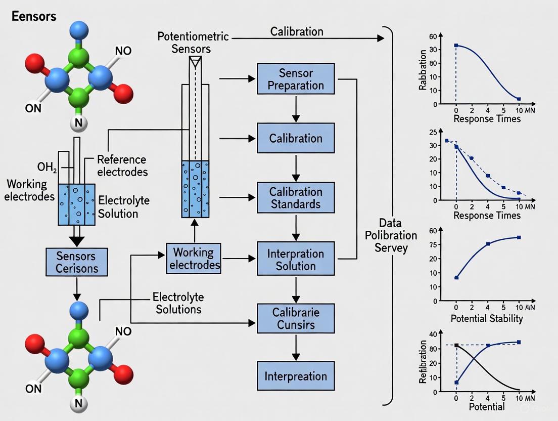
Theoretical Workflow and Signaling Pathways
The following diagram illustrates the logical sequence of applying the Nernst equation from fundamental theory to practical sensor output and data interpretation.
The Scientist's Toolkit: Key Research Reagent Solutions
Table 2: Essential Materials for Potentiometric Sensor Development and Experimentation
| Research Reagent / Material | Function / Explanation | Reference |
|---|---|---|
| Ionophore (e.g., Valinomycin for K⁺) | A selective ion carrier embedded in the sensor membrane. It is the primary recognition element that dictates selectivity by complexing with the target ion [7] [8]. | [7] [8] |
| Ionic Additive (e.g., KTPB, TDDMA-NO₃) | A lipophilic salt added to the membrane. It reduces membrane resistance, diminishes anion interference, and helps establish a stable internal potential by providing immobile ionic sites [7]. | [7] |
| Polymer Matrix (e.g., PVC) | Forms the bulk of the sensing membrane, providing a solid yet plasticized support that holds the ionophore and ionic additives [7] [8]. | [7] [8] |
| Plasticizer (e.g., NPOE) | Imparts liquidity and flexibility to the PVC membrane, facilitating ion dissolution and mobility, which is crucial for a fast and stable response [7]. | [7] |
| Solid Contact Material (e.g., Mesoporous Carbon Black) | In solid-contact ISEs, this material acts as an ion-to-electron transducer between the ion-conducting membrane and the electron-conducting electrode substrate, improving potential stability [7]. | [7] |
| Electroplating Solution (for Ag/AgCl Reference) | Used to fabricate and chloridize silver wires to create stable, reversible Ag/AgCl reference electrodes, which are essential for completing the electrochemical cell [7]. | [7] |
What is the unique aspect of defining LOD in potentiometry?
In potentiometry, the Limit of Detection (LOD) is defined differently than in most other analytical techniques. While other methods typically define LOD as the concentration giving a signal three times the standard deviation of the noise (blank), potentiometry uses a graphical method involving the intersection of two linear portions of the response curve [8].
This unique definition means you cannot directly compare LOD values from potentiometric sensors with those from other analytical methods like voltammetry or atomic spectrometry. The potentiometric LOD will always appear higher, even though the actual sensitivity might be comparable [8].
Key Difference in Definitions:
- General Analytical Chemistry LOD: Based on signal-to-noise ratio (typically 3× standard deviation of blank measurements) [11] [12]
- Potentiometric LOD: Defined as the intersection point of the two linear segments of the calibration curve [8]
Why does potentiometry use a different LOD definition?
Potentiometry uses this different definition because of the logarithmic nature of the sensor response described by the Nernst equation. The detection limit is mechanistically defined as the concentration where a significant amount (approximately 50% for equal charge ions) of the primary ions in the sensor membrane are replaced by interfering ions [8].
At this specific point, the potential deviation from the final baseline value is approximately 17.8/z mV (where z is the ion charge). Since typical potentiometric measurement noise is much lower (0.06-0.08 mV), the "true" detection limit based on noise is actually about two orders of magnitude lower than the officially defined potentiometric LOD [8].
How do I properly determine the LOD for my potentiometric sensor?
Standard Potentiometric LOD Determination Protocol:
Generate a full calibration curve by measuring the electrode potential across a wide concentration range, from high concentrations to very dilute samples [8]
Plot the potential (EMF) against the logarithm of the ion activity (not concentration) to obtain the characteristic sigmoidal response curve [8]
Identify the two linear regions of the plot:
- The Nernstian slope region at higher concentrations
- The constant potential region at low concentrations where the sensor responds mainly to interfering ions
Calculate the LOD by finding the concentration at the intersection point of these two linear segments [8]
For quality control, you should validate this LOD by analyzing multiple samples (n ≥ 6) near the calculated detection limit to ensure consistent performance [11].
What are common issues when determining LOD in potentiometry and how can I troubleshoot them?
| Problem | Possible Causes | Troubleshooting Solutions |
|---|---|---|
| Poor detection limits | Ion fluxes from membrane to sample; insufficiently selective ionophore; membrane contamination [8] | Use optimized inner solutions with complexing agents (EDTA, resins) [8]; implement rotating electrode systems [8] |
| Non-linear calibration | Insufficient conditioning; membrane fouling; reference electrode instability [13] | Extend electrode conditioning time; clean membrane surface; verify reference electrode potential |
| High signal noise | Electrical interference; poor shielding; unstable reference electrode [13] | Use Faraday cage; ensure proper grounding; check reference electrode filling solution |
| Inconsistent LOD values | Changes in membrane composition; varying experimental conditions [8] | Standardize membrane fabrication; control temperature and pH across experiments |
What experimental factors most affect LOD in potentiometric sensors?
The detection limit in potentiometric sensors is influenced by several key factors:
- Membrane composition: The choice of ionophore, plasticizer, and polymer matrix significantly impacts selectivity and detection limits [8]
- Inner solution optimization: Adding complexing agents (EDTA, NTA) or ion-exchange resins to the inner solution can dramatically lower LODs by controlling ion fluxes [8]
- Solid-contact designs: Eliminating the inner solution with solid-contact electrodes can improve detection limits and stability [13]
- Measurement protocol: Using rotating electrodes or stirred solutions can enhance mass transport and lower detection limits [8]
How can I achieve the lowest possible LOD for trace-level analysis?
Advanced strategies for ultra-low detection limits include:
- Incorporating nanoparticles in solid-contact layers to enhance capacitance and signal stability [13]
- Using composite materials such as MoS₂ nanoflowers with Fe₃O₄ or tubular gold nanoparticles with tetrathiafulvalene as transduction layers [13]
- Implementing advanced membrane designs with covalently attached ligands or plasticizer-free polymers [8]
- Optimizing inner solutions with appropriate complexing agents tailored to your target ion [8]
With these approaches, researchers have achieved detection limits as low as 10⁻¹¹ M for calcium ions and 8×10⁻¹¹ M for lead ions in practical applications [8].
Research Reagent Solutions for Potentiometric Sensor Development
| Reagent/Material | Function in Sensor Development | Application Notes |
|---|---|---|
| Ion-selective ionophores | Provides selective binding for target ions | Critical for sensor selectivity; choose based on complexation constants |
| Lipophilic ion exchangers | Maintains ionic equilibrium in membrane | Typically tetraphenylborate derivatives; prevents Donnan exclusion failure |
| Polymer matrix (PVC, PU) | Forms the sensing membrane structure | Affects response time and lifetime; PVC most common |
| Plasticizers | Provides mobility for ion exchange | DOS, NPOE common; affects dielectric constant and selectivity |
| Solid-contact materials | Replaces inner solution in SC-ISEs | Conducting polymers (PEDOT, PANI) or carbon nanomaterials |
| Inner solution additives | Controls ion fluxes to lower LOD | EDTA, NTA, or ion-exchange resins for specific applications |
Experimental Workflow for LOD Determination
Relationship Between Different LOD Definitions
Liquid-Contact vs. Solid-Contact Ion-Selective Electrodes (SC-ISEs)
FAQ: Electrode Architecture and Selection
Q1: What is the fundamental architectural difference between liquid-contact and solid-contact ISEs?
The core difference lies in the internal structure used for ion-to-electron transduction.
- Liquid-Contact ISEs (LC-ISEs) rely on an internal filling solution that contacts the inner surface of the Ion-Selective Membrane (ISM). An inner reference electrode (e.g., Ag/AgCl) immersed in this solution facilitates the electrical potential measurement [14].
- Solid-Contact ISEs (SC-ISEs) eliminate the liquid phase. A solid-contact (SC) layer is placed between the ion-selective membrane and the electronic conductor substrate. This SC layer acts as the ion-to-electron transducer, simplifying the electrode structure and enabling miniaturization [14].
The following diagram illustrates the fundamental difference in the signal transduction pathway between the two architectures.
Q2: Why would I choose a solid-contact ISE over a traditional liquid-contact design?
SC-ISEs offer several key advantages that make them suitable for modern applications [14]:
- Easy Miniaturization and Integration: The absence of a liquid inner solution makes them ideal for lab-on-a-chip devices, wearable sensors, and other compact formats.
- Robustness and Portability: No risk of internal solution evaporation, leakage, or pressure-induced volume changes, making them suitable for on-site and field measurements.
- Simplified Manufacturing: The all-solid-state structure is often more conducive to mass production and commercialization.
LC-ISEs, while potentially offering high stability in controlled benchtop environments, are generally not suitable for miniaturized, portable, or wearable devices due to the inherent limitations of the internal filling solution [14].
Q3: What are the common failure modes for SC-ISEs, and how can they be diagnosed?
The performance and reproducibility of SC-ISEs can be compromised by several factors [15]:
- Water Layer Formation: If the solid-contact layer is not sufficiently hydrophobic, a thin aqueous layer can form between the ISM and the SC layer. This introduces a drifting, unstable potential and is a major source of error.
- Diagnosis: Observe a continuous, long-term potential drift even after the initial conditioning period.
- Poor Ion-Electron Transduction: An inefficient solid-contact layer can lead to high impedance and slow response.
- Diagnosis: Measure a non-Nernstian slope during calibration or a slow response time when the analyte concentration changes.
- Sensitivity to Environmental Factors: Some SC materials can be sensitive to changes in ambient light, oxygen, or pH, leading to parallel drift.
- Diagnosis: Observe potential shifts when environmental conditions (like O₂ or light levels) are altered.
Troubleshooting Common Experimental Issues
Poor Reproducibility and Signal Drift
| Symptom | Potential Cause | Recommended Solution |
|---|---|---|
| Continuous potential drift after conditioning. | Formation of a water layer between ISM and SC layer [15]. | Use highly hydrophobic SC materials (e.g., 3D porous carbons) and ensure membrane components are sufficiently lipophilic to prevent water uptake [15]. |
| Drift upon changes in light, O₂, or pH. | SC layer is sensitive to environmental interferents [15]. | Select environmentally inert SC materials (e.g., certain conducting polymers or carbon-based materials) and shield the sensor from light/gas if necessary [15]. |
| Poor reproducibility between electrodes from the same batch. | Inconsistent fabrication of the SC layer or ISM [15]. | Standardize and严格控制 fabrication protocols (e.g., drop-casting volume, polymerization time/potential). Use SC materials that promote high potential reproducibility [15]. |
Experimental Protocol: Conditioning SC-ISEs Conditioning is a critical step to achieve a stable and hydrated state before measurement.
- Preparation: Soak the newly fabricated or dry-stored SC-ISE in a solution containing the primary ion of interest.
- Solution: Use a standard solution with a low concentration of the primary ion, typically one of your calibration standards [16].
- Duration: A common standard procedure is to condition for at least 24 hours [15]. Satisfactory performance for some applications may be achieved in a shorter period, but significant drift beyond 24 hours often indicates an inadequate SC layer [16] [15].
Calibration and Measurement Inaccuracy
| Symptom | Potential Cause | Recommended Solution |
|---|---|---|
| Non-Nernstian calibration slope. | Degraded ionophore activity, incorrect membrane composition, or faulty SC layer [16]. | Re-prepare the ISM, ensuring correct ratios of ionophore, polymer, and plasticizer. Verify the performance of the SC layer. |
| Inaccurate concentration readout in real samples. | Difference in ionic strength/background between calibration standards and sample, affecting ion activity [16] [17]. | Use calibration standards that closely match the sample's background matrix (e.g., interfering ions, pH, ionic strength). Consider using the Standard Addition method for analysis [16]. |
| Erratic and noisy readings. | Air bubbles on the sensing surface or poor electrical contact [16]. | Install the sensor at a 45-degree angle (for flow cells or tanks) to prevent bubble accumulation. Gently shake the sensor downward to dislodge any trapped air. Check all electrical connections [16]. |
Experimental Protocol: Two-Point Calibration for ISEs Calibration by interpolation is strongly recommended over extrapolation for higher accuracy [16].
- Select Standards: Choose two calibration solutions whose concentrations bracket the anticipated sample concentration and are not more than one decade apart [16].
- Conditioning Rinse: Rinse the conditioned sensor with the first (lower concentration) calibration solution. This shortens the response time [16].
- First Point: Immerse the sensor in the first solution, wait for the potential to stabilize, and record the reading.
- Second Point: Rinse the sensor with the second calibration solution and repeat the measurement. Avoid rinsing with deionized water between standards, as this dilutes the surface concentration and prolongs response time [16].
- Validation: Re-calibrate periodically to validate the sensor's sensitivity (slope) has not changed [16].
The following diagram outlines the critical steps in the preparation, conditioning, and calibration of a reliable SC-ISE.
The Scientist's Toolkit: Key Reagents and Materials
The table below lists essential components for developing and working with Solid-Contact ISEs.
| Item | Function | Example Components |
|---|---|---|
| Ionophore | The active sensing element; selectively binds to the target ion. | Valinomycin (for K+), Schiff bases (e.g., for Cu²⁺ [18]), synthetic ionophores [14] [17]. |
| Polymer Matrix | Provides the structural backbone for the Ion-Selective Membrane (ISM). | Polyvinyl chloride (PVC), acrylic esters, polyurethane [14]. |
| Plasticizer | Confers plasticity and fluidity to the ISM; can influence dielectric constant and ionophore selectivity. | Bis(2-ethylhexyl) sebacate (DOS), o-Nitrophenyl octyl ether (o-NPOE), Dioctyl phthalate (DOP) [14] [18]. |
| Ion Exchanger | Introduces oppositely charged sites into the membrane to aid ion exchange and enforce Donnan exclusion. | Sodium tetrakis(pentafluorophenyl)borate (NaTFPB), Potassium tetrakis(4-chlorophenyl)borate (KTPCIPB) [14]. |
| Solid-Contact (SC) Material | Acts as the ion-to-electron transducer; critical for potential stability. | Conducting Polymers (Redox Capacitance): PEDOT, Polypyrrole [14]. Nanoporous Carbons (Double-Layer Capacitance): 3D ordered mesoporous carbon, graphene [14] [15]. |
| Electronic Conductor Substrate | Provides the electrical connection to the measuring instrument. | Glassy Carbon (GC), Gold (Au), Graphite-based inks [15] [18] [17]. |
The Critical Role of Ion-Selective Membranes and Ionophores
Fundamental Concepts: FAQs
FAQ 1: What is the fundamental role of an ionophore in a potentiometric sensor? An ionophore (meaning "ion bearer") is a critical component dissolved in the ion-selective membrane of a sensor. Its function is to reversibly bind to a specific target ion, facilitating its transport across the otherwise impermeable hydrophobic membrane [19] [20]. This selective binding creates a potential difference at the membrane-solution interface, which is the primary signal measured by the ion-selective electrode (ISE) [21]. The ionophore's key property is its selectivity, determining how well the sensor can distinguish the primary ion from interfering ions in the sample [22].
FAQ 2: How does an ion-selective membrane differ from a simple filter? An ion-selective membrane is not a simple physical filter. It is a sophisticated chemical system that generates an electrical potential. It typically consists of a polymer matrix (like PVC) plasticized to remain fluid, in which several key components are dissolved: the ionophore (the ion-recognition element), a lipophilic salt (to reduce unwanted anion interference), and the ionophore-ion complex itself [21] [23]. The membrane works by establishing an ion-exchange equilibrium at the interface, where the ionophore selectively extracts the target ion from the sample solution into the organic membrane phase. This selective partitioning creates the measurable potential [21].
FAQ 3: Why is valinomycin the gold standard for potassium-selective electrodes? Valinomycin is a naturally occurring, macrocyclic ionophore produced by Streptomyces species. It is renowned for its exceptional selectivity for potassium (K+) over sodium (Na+), with a selectivity coefficient (KpotK,Na) of approximately 10-4 [20]. This means valinomycin is 10,000 times more selective for K+ than for Na+ [20]. Its structure features a hydrophobic exterior that allows it to dissolve in the membrane and a polar interior lined with carbonyl oxygens that perfectly chelate a K+ ion, making it an ideal carrier for potentiometric sensing [21] [20].
Troubleshooting Common Experimental Issues
FAQ 4: My sensor shows a slow or drifting response. What could be the cause? A slow or drifting response can stem from several issues related to the membrane or experimental conditions:
- Membrane Degradation: The ionophore or other membrane components can be slowly lost (leached) from the membrane into the sample solution, especially during long-term measurements or in large sample volumes [23]. This degrades the membrane's performance over time.
- Clogged Channels: With use, the ion-sensitive channels in the membrane can become blocked or inactivated, causing a loss of sensitivity [23].
- Insufficient Equilibration: Newly prepared or stored sensors require adequate conditioning in a solution containing the target ion to establish a stable equilibrium at the membrane surface [24].
- Reference Electrode Issues: A unstable reference electrode potential, often due to a clogged junction or changing internal solution concentration, will manifest as signal drift in the overall cell potential [23].
FAQ 5: The sensor response is non-Nernstian or the sensitivity is low. How can I diagnose this? A deviation from the theoretical Nernstian slope (e.g., ~59 mV per decade for a monovalent ion at 25°C) indicates a problem with sensor performance.
- Check the Membrane Composition: An incorrect ratio of ionophore to polymer, or the absence of a lipophilic ionic additive, can prevent the proper functioning of the transduction mechanism, leading to a reduced slope [21].
- Confirm Calibration Standards: Use fresh, accurately prepared standard solutions. Contaminated or outdated standards are a common source of error [24].
- Identify Interfering Ions: No ISE is completely specific. Highly concentrated interfering ions with similar properties can cause a biased or suppressed response. Consult the selectivity coefficients for your ionophore to identify potential interferents [23] [22]. For example, perchlorate is a severe interferent for nitrate electrodes [23].
- Temperature Effects: The Nernstian slope is temperature-dependent. Ensure measurements and calibrations are performed at a stable temperature [23].
FAQ 6: How can I manage interference from other ions in my sample? Ion interference is a fundamental challenge in potentiometry. Management strategies include:
- Selectivity Coefficients: Understand the published selectivity coefficients (KpotA,B) for your ionophore-membrane system. These values quantify the sensor's relative response to the primary ion (A) versus an interfering ion (B) [22].
- Sample Pretreatment: Adjust the sample pH or add a masking agent to complex or precipitate the interfering ion before measurement [7].
- Standard Addition Method: This method can be used to compensate for constant levels of interference, as it measures the change in signal upon adding a known quantity of the analyte to the sample itself [25].
- Empirical Methods: For complex real-world samples, empirical methods like the Matched Potential Method can provide a more practical assessment of apparent selectivity than traditional theoretical models [22].
Experimental Protocols & Best Practices
Detailed Protocol: Two-Point Calibration of an Ion-Selective Electrode
Regular calibration is essential for accurate quantification. The following protocol is adapted from standard procedures for chloride ISEs and integrated sensor systems [24] [7].
1. Preparation and Conditioning:
- Soak the ISE in the high-concentration standard solution (e.g., 1000 mg/L Cl⁻) for at least 30 minutes before the first use of the day. The ISE should not touch the container's bottom, and the reference junctions must be fully immersed [24].
- Use a magnetic stirrer to gently stir all solutions during calibration and measurement, as most ISE measurements are performed under moving conditions [24].
2. First Calibration Point (High Standard):
- Ensure the ISE is still in the high standard solution.
- Connect the sensor to the meter/readout system and initiate the calibration procedure.
- Enter the concentration value of the high standard (e.g., 1000 mg/L).
- Wait for the potential reading to stabilize (a stable drift of < 1 mV per 10 seconds is a good indicator).
- Accept the reading [24].
3. Rinsing and Second Calibration Point (Low Standard):
- Carefully remove the ISE from the high standard.
- Rinse the sensing membrane thoroughly with deionized water from a wash bottle and gently blot it dry with a lint-free tissue to avoid cross-contamination.
- Place the ISE into the low-concentration standard solution (e.g., 10 mg/L Cl⁻).
- Enter the concentration value of the low standard.
- Wait for the signal to stabilize.
- Accept the reading to complete the calibration [24].
4. Verification (Best Practice):
- Measure a third standard solution with a concentration within the calibrated range to verify the accuracy of the calibration curve.
Advanced Protocol: Sensor System with Automated Self-Calibration
For long-term, in-situ monitoring, systems with integrated self-calibration are being developed. The workflow of such a system is illustrated below and involves embedding the sensor within a microfluidic flow cell [7].
Figure 1: Automated self-calibration workflow for in-situ potentiometric sensors [6] [7].
The Scientist's Toolkit: Key Research Reagents & Materials
Table 1: Essential Materials for Fabricating and Using Ion-Selective Electrodes.
| Item | Function & Rationale | Example(s) |
|---|---|---|
| Ionophore | The molecular recognition element; determines selectivity and sensitivity by reversibly binding the target ion. | Valinomycin (for K+ [21] [20]), 8-hydroxyquinoline derivatives (for Zn2+ [19]), Tridodecylmethylammonium nitrate (TDDMA-NO3, for NO3- [7]). |
| Polymer Matrix | Forms the backbone of the solid membrane, providing mechanical stability and housing the other components. | Polyvinyl Chloride (PVC) is the most common polymer used [7]. |
| Plasticizer | Imparts fluidity to the membrane, allowing ionophore and ion mobility; influences dielectric constant and selectivity. | 2-Nitrophenyl octyl ether (NPOE), bis(2-ethylhexyl) sebacate, various phthalates [7] [23]. |
| Lipophilic Additive | Minimizes unwanted anion interference by reducing the membrane's electrical resistance and stabilizing the phase boundary potential. | Potassium tetrakis(4-chlorophenyl)borate (KTPB) [7]. |
| Solid Contact Material | In solid-contact ISEs (SCISEs), this material acts as an ion-to-electron transducer, replacing the inner filling solution to enhance stability and miniaturization. | Mesoporous carbon black (MCB), poly(3-octylthiophene), other conducting polymers [7]. |
| Reference Electrode | Provides a stable, constant potential against which the potential of the ISE is measured to complete the electrochemical cell. | Ag/AgCl electrode, saturated calomel electrode (SCE) [23]. |
Table 2: Typical Performance Specifications for a Commercial Chloride Ion-Selective Electrode [24].
| Parameter | Specification | Notes / Relevance |
|---|---|---|
| Measuring Range | 1 to 35,000 mg/L (ppm) | Covers a wide dynamic range for various applications. |
| Accuracy | ±10% of full scale | Highlights the importance of calibration within the expected concentration range. |
| Slope | –56 ± 3 mV/decade at 25°C | Close to the theoretical Nernstian value (–59.16 mV/decade) indicates good performance. |
| Reproducibility | ±30 mV | The potential for the same concentration can vary; hence, calibration is mandatory. |
| pH Range | 2 – 12 | The sensor can be used in a wide range of pH conditions without compensation. |
| Key Interfering Ions | CN⁻, Br⁻, I⁻, OH⁻, S²⁻ | These ions must be absent or present in very low concentrations for reliable Cl⁻ measurement. |
Visualization of Ionophore Mechanism and Signal Transduction
The following diagram illustrates the critical mechanism of how a carrier ionophore, such as valinomycin, facilitates the generation of a potentiometric signal within a sensor membrane.
Figure 2: Ionophore-mediated signal transduction in a potentiometric sensor [19] [21] [20].
Technical Support Center: Troubleshooting Guides and FAQs
This technical support center is designed for researchers working with advanced potentiometric sensor platforms. It integrates specific troubleshooting for 3D-printed, paper-based, and wearable sensors within the broader context of a thesis on calibration best practices, ensuring data integrity and sensor reliability.
Core Principles of Potentiometric Sensor Calibration
This section addresses fundamental calibration challenges applicable to all novel sensor platforms.
FAQ 1: What are the foundational calibration requirements for novel solid-contact ion-selective electrodes (SC-ISEs)?
Solid-contact ISEs, common in modern platforms, eliminate the inner filling solution of traditional electrodes but require specific calibration considerations. The key parameters to monitor and validate are summarized in the table below [13].
Table 1: Key Performance Parameters for Solid-Contact Potentiometric Sensors
| Parameter | Target Performance | Importance for Calibration |
|---|---|---|
| Nernstian Slope | Close to theoretical value (e.g., ~59.2 mV/dec for monovalent ions at 25°C) | Confirms sensor is responding correctly to activity changes. Significant deviation requires investigation. |
| Response Time | Typically < 30 seconds [18] | Determines how long to wait between standard additions or sample measurements during calibration. |
| Detection Limit | Low, e.g., 10⁻⁷ to 10⁻⁸ mol L⁻¹ for high-performance sensors [18] | Defines the lower limit of the usable calibration range. |
| Working pH Range | Stable potential across a defined pH window (e.g., 3.5-6.5) [18] | Ensures sample pH is adjusted to within this range before calibration/measurement to avoid bias. |
| Lifespan | Weeks to months [18] | Calibration frequency may need to increase as the sensor ages. |
FAQ 2: Our sensor readings drift over time. How can we monitor and correct for this, especially in field-deployed sensors?
Voltage drift is a major challenge for long-term, in-situ measurements. Instead of frequent manual recalibration, innovative methods using temperature variation have been developed [26].
- Root Cause: Drift can be caused by changes in the sensor membrane, the solid-contact layer, or the reference electrode.
- Solution (In-Situ Monitoring): Implement a temperature-supervised drift monitoring method. This approach uses natural or external temperature variations in the field to track time-varying calibration parameters without relocating the sensor or using standard solutions [26].
- Protocol: In-Situ Drift Correction Using Temperature Supervision
- Characterize Sensor: Initially, characterize the sensor's temperature-response relationship under controlled lab conditions.
- Deploy with Monitoring: Deploy the sensor with integrated temperature logging.
- Model Drift: Use the recorded temperature data and the pre-characterized model to monitor and estimate signal drift during operation.
- Periodic Correction: Periodically apply the drift-correction algorithm to the raw potentiometric data to achieve high-precision sensing. This method has been shown to maintain accuracy within 10% of laboratory measurements for periods as long as 22 days [26].
The following diagram illustrates the logical workflow for implementing this in-situ monitoring strategy.
Platform-Specific Troubleshooting
Here we address issues unique to each novel sensor platform.
3D-Printed Sensors
FAQ 3: Our 3D-printed sensors show poor reproducibility and inconsistent performance. What are the key fabrication factors to control?
3D printing offers incredible customization but introduces variability from the manufacturing process itself [27] [28].
- Root Cause: Inconsistencies can stem from the printing technology (e.g., Fused Deposition Modeling (FDM), stereolithography (SLA)), print orientation, layer height, and the properties of the functional materials (e.g., conductive polymers, graphite composites) [28].
- Solution:
- Material Selection: Use specialized functional materials like conductive polymers (e.g., PEDOT:PSS), flexible thermoplastic polyurethanes (TPU), or graphite-based composites designed for 3D printing [27] [29] [18].
- Print Optimization: Thoroughly optimize and document all printing parameters (e.g., nozzle temperature, print speed, layer height) and keep them constant for a given production batch.
- Post-Processing: Implement consistent post-processing steps, such as curing (for SLA resins) or annealing, to stabilize the sensor's electrochemical properties.
FAQ 4: How do we integrate a sensor with a microfluidic self-calibration system?
Integrating a sensor into a microfluidic flow cell is a robust method for automated self-calibration [7].
- Protocol: Fabrication of a Microfluidic Flow Cell for Self-Calibration
- Fabricate Sensor: Fabricate the SC-ISE on a suitable substrate (e.g., a printed circuit board (PCB)) using techniques like drop-casting [7].
- 3D Print Enclosure: Design and 3D-print a microfluidic enclosure with inlet/outlet ports using a high-resolution technology like stereolithography (SLA) [7].
- Bonding: Bond the enclosure to the sensor substrate using a double-sided adhesive tape patterned with a laser cutter to form the microchannel [7].
- Fluidic Control: Connect the ports to a miniaturized peristaltic pump and solenoid valves, which are controlled by a custom PCB circuit. This setup allows for the automated sequential delivery of calibrants and samples over the sensor [7].
- Calibration Cycle: Program the system to perform a two-point calibration at set intervals, drastically reducing the need for manual intervention and ensuring long-term measurement accuracy [7].
Paper-Based Sensors
FAQ 5: The response of our paper-based sensors is unstable. How can we improve their reliability for point-of-care testing?
Paper-based sensors are cost-effective but can suffer from evaporation and sample volume variations.
- Root Cause: Unstable response can be due to inconsistent wicking of the sample, evaporation leading to concentration changes, or poor contact between the paper substrate and the electrodes.
- Solution:
- Wax Patterning: Use wax printing or other hydrophobic barriers to define precise and reproducible microfluidic channels on the paper [13].
- Material Modification: Modify the paper with chemical reagents or ion-selective membranes to enhance selectivity and stability, similar to those used in conventional ISEs [13].
- Environmental Control: Perform measurements in a controlled environment (e.g., a closed chamber) to minimize evaporation during the reading.
Wearable Sensors
FAQ 6: How can we manage drift and calibration for a wearable sensor that is continuously monitoring analytes in sweat?
Wearable sensors are subject to motion artifact, variable skin contact, and changing analyte levels.
- Root Cause: Signal drift in wearables is exacerbated by the dynamic conditions of use, including temperature fluctuations, pH changes in sweat, and mechanical stress on the sensor [26] [29].
- Solution:
- In-Situ Calibration: Leverage the temperature-supervised drift monitoring method described in FAQ 2, as it is well-suited for on-body applications with natural temperature variations [26].
- Multi-Sensing Platform: Co-integrate other sensors (e.g., pH, temperature) to correct for interfering effects on the primary ion-selective sensor [13].
- On-Body Calibration: Design the device to allow for periodic single-point calibration using an integrated reservoir of standard solution or by using a "zero" reading from a known state (e.g., freshly secreted sweat) [13].
Essential Experimental Protocols & Reagents
This section provides a detailed methodology for a key experiment and a toolkit of essential materials.
Detailed Protocol: Fabrication and Calibration of a Graphite-Based Solid-Contact Cu(II) Sensor [18]
This protocol is an excellent example of creating a highly selective sensor, a common goal in research and drug development.
- Synthesis of Ionophore: Synthesize the Schiff base ligand 2-(((3-aminophenyl) imino) methyl) phenol by a condensation reaction of m-phenylenediamine and 2-hydroxybenzaldehyde in ethanol under reflux for 3 hours. Purify the yellowish-green solid product via recrystallization [18].
- Sensor Fabrication:
- In a mortar, thoroughly mix 250 mg of graphite powder, 5–20 mg of the synthesized Schiff base ionophore, and 0.1 mL of a plasticizer (e.g., o-nitrophenyl octyl ether - o-NPOE).
- Pack the resulting modified carbon paste into a Teflon electrode holder.
- Establish electrical contact by inserting a stainless-steel rod into the paste.
- Polish the sensor surface on a clean filter paper before each use to create a fresh, reproducible sensing interface [18].
- Calibration and Validation:
- Calibration: Immerse the sensor and a reference electrode (e.g., Ag/AgCl) in a series of standard Cu(II) solutions (e.g., from 1 × 10⁻⁷ to 1 × 10⁻¹ mol L⁻¹). Measure the potential in each solution and plot the potential (mV) vs. log[Cu²⁺]. The slope should be near-Nernstian (~29.6 mV/decade) [18].
- Selectivity Check: Perform a separate solution method (SSM) or fixed interference method (FIM) by measuring the potential in solutions containing potential interfering ions (e.g., Zn²⁺, Ni²⁺, Ca²⁺) to determine the selectivity coefficients [18].
- Real Sample Validation: Validate the sensor's accuracy by measuring Cu(II) in spiked real samples (e.g., water, plant sap, pharmaceutical samples) and comparing the results with a standard method like atomic absorption spectroscopy (AAS) [7] [18].
Table 2: Research Reagent Solutions for Potentiometric Sensor Development
| Reagent/Material | Function/Application | Example Use Case |
|---|---|---|
| Schiff Base Ligands | Acts as an ionophore for selective ion recognition. | Selective determination of Cu(II) ions in a carbon paste electrode [18]. |
| Conductive Polymers (e.g., PEDOT:PSS) | Serves as a solid-contact (ion-to-electron transducer) in SC-ISEs. | Improving stability and signal transduction in miniaturized and wearable sensors [13]. |
| Plasticizers (e.g., o-NPOE, DOS) | Imparts mobility to the ionophore in the sensor membrane, influencing selectivity and lifespan. | Forming the hydrophobic ion-selective membrane in PVC or carbon paste electrodes [18]. |
| Graphite/Carbon Black | Provides a conductive matrix for the sensing membrane; base material for carbon paste electrodes. | Used as the bulk material in simple, reproducible, and low-cost carbon paste electrodes [18]. |
| Thermoplastic Polyurethane (TPU) | A flexible polymer used in 3D printing (FDM). | Creating flexible, wearable sensor housings or substrates that conform to the body [29]. |
| Mesoporous Carbon Black | High-surface-area solid-contact material for SC-ISEs. | Used as an ion-to-electron transducer in PCB-fabricated nitrate and potassium sensors [7]. |
The following diagram outlines the complete workflow for developing and validating a novel potentiometric sensor, from design to deployment.
Calibration in Practice: From Traditional Methods to Advanced Automated Systems
Troubleshooting Guides and FAQs
Frequently Asked Questions
Q1: What are the main differences between the Separate Solution and Two-Point Calibration methods? The Separate Solution Method (SSM) requires measurements in separate, pure standard solutions for each ion of interest to determine individual electrode parameters, making it useful for characterizing new sensors or complex arrays [30]. In contrast, the Two-Point Calibration uses two known reference points (typically low and high) to correct for both slope and offset errors in a single measurement range, making it efficient for routine calibration of sensors with reasonably linear response [31].
Q2: My calibration curve shows significant nonlinearity. What could be the cause? Nonlinearity in potentiometric sensors can result from several factors. Membrane degradation or contamination can reduce electrode responsiveness. Selectivity issues may arise when interfering ions affect the primary ion measurement. Sensor saturation can occur outside the optimal linear range, while temperature fluctuations may destabilize the electrochemical system [32] [33]. For accurate measurements, it's recommended to perform calibration within the specific pH range of your samples rather than across the entire 0-14 pH scale [32].
Q3: Why does my sensor signal drift over time, and how can I correct it? Signal drift is a common challenge in potentiometric measurements. Causes include reference electrode instability, membrane leaching or fouling, and changes in temperature or pressure [33]. Modern solutions incorporate automated recalibration systems with integrated microfluidics to perform periodic two-point calibrations, significantly improving long-term measurement stability for in situ applications [7].
Q4: When should I use a mixed standard solution versus separate pure standards? Mixed standard solutions are particularly valuable when working with sensor arrays or limited sample volumes, as they can reduce the number of required calibration standards to a minimum while maintaining accuracy comparable to traditional methods [30]. Separate pure standards remain essential for initial sensor characterization and determining fundamental parameters like selectivity coefficients.
Troubleshooting Common Problems
| Problem | Possible Causes | Recommended Solutions |
|---|---|---|
| Excessive Signal Noise [33] | Electromagnetic interference, Poor connections, Vibration | Use shielded cables, Check all connectors, Implement vibration damping |
| Constant Offset [33] | Calibration errors, Reference electrode drift, Membrane bias | Perform fresh two-point calibration, Check reference electrode, Replace sensor if biased |
| Reduced Sensitivity [32] | Membrane aging, Contamination, Incorrect slope | Recalibrate using two-point method, Clean or replace membrane, Verify standard concentrations |
| Slow Response Time | Membrane fouling, Junction clogging, Sample viscosity | Clean membrane surface, Clear reference junction, Allow adequate equilibration time |
Comparison of Calibration Methods
| Parameter | Two-Point Calibration | Separate Solution Method |
|---|---|---|
| Number of Standards | 2 reference points [31] | Multiple pure standards [30] |
| Primary Application | Routine calibration of linear sensors [31] | Sensor characterization & validation [30] |
| Error Correction | Slope and offset [31] | Individual electrode parameters [30] |
| Time Requirement | Fast (typically <5 minutes) | Longer (multiple measurements) |
| Data Processing | Simple linear correction [31] | Multi-parameter optimization [30] |
Experimental Protocols
Two-Point Calibration Methodology
The two-point calibration method provides efficient correction for both slope and offset errors in sensors demonstrating reasonably linear response over the measurement range [31].
Equipment and Reagents Required:
- Potentiometric sensor and readout system
- Two reference standards spanning expected measurement range
- Temperature control system (if temperature-sensitive)
- Data recording system
Step-by-Step Procedure:
Select Reference Points: Choose two reference values (ReferenceLow and ReferenceHigh) that bracket your expected measurement range. For temperature sensors, common references are 0.01°C (triple point of water) and 100°C (boiling point) [31].
Record Reference Measurements: Take sensor measurements at both reference points, recording these values as RawLow and RawHigh.
Calculate Ranges:
- RawRange = RawHigh - RawLow
- ReferenceRange = ReferenceHigh - ReferenceLow
Apply Correction: For any new sensor reading (RawValue), calculate the corrected value using:
- CorrectedValue = (((RawValue - RawLow) × ReferenceRange) / RawRange) + ReferenceLow [31]
Example Calculation: For a thermometer with RawLow = -0.5°C and RawHigh = 96.0°C measuring a sample at RawValue = 37°C:
- RawRange = 96.5°C
- Using ReferenceLow = 0.01°C and ReferenceHigh = 100°C (ReferenceRange = 99.99)
- CorrectedValue = (((37 - (-0.5)) × 99.99) / 96.5) + 0.01 = 38.9°C [31]
Separate Solution Method for Sensor Arrays
The Separate Solution Method is particularly valuable for characterizing sensor arrays with a reduced number of standards, optimizing the determination of multiple ion-selective electrode parameters [30].
Equipment and Reagents Required:
- Array of ion-selective electrodes
- Pure standard solutions for each ion of interest
- Mixed standard solutions containing multiple ions
- Potentiometric data acquisition system
- Software for parameter optimization (e.g., specialized potentiometric data processing software) [34]
Step-by-Step Procedure:
Standard Preparation: Prepare pure standard solutions for each primary ion of interest. Additionally, design mixed standard solutions containing combinations of target ions [30].
Measurement Sequence: Immerse the sensor array in each standard solution, recording the stable potential reading for each sensor.
Parameter Determination: Using the Nicolsky-Eisenman model, determine electrode parameters based on the response across different standard types.
Verification: Validate the calibrated parameters with test solutions to ensure accuracy across the expected measurement range.
Key Advantage: This approach can reduce the total number of required calibration standards while maintaining accuracy comparable to traditional methods, making it particularly efficient for multicomponent analysis systems [30].
Essential Research Reagents and Materials
| Item | Function | Application Notes |
|---|---|---|
| Ion-Selective Membranes | Primary sensing element | Composition varies by target ion (e.g., valinomycin for K+) [7] |
| Solid-Contact Materials | Ion-to-electron transduction | Mesoporous carbon black provides stable potential [7] |
| Reference Electrode | Stable potential reference | Ag/AgCl systems commonly used [35] |
| Buffer Solutions | pH calibration | Certified buffers traceable to NIST standards |
| Primary Ion Standards | Calibration reference | Pure solutions for separate solution method [30] |
| Mixed Ion Standards | Array calibration | Contains multiple ions for efficient calibration [30] |
Workflow Diagrams
Two-Point Calibration Workflow
Separate Solution Method Workflow
Sensor Troubleshooting Decision Tree
Innovative Autocalibration Strategies for Disposable Test Strips
# Frequently Asked Questions (FAQs)
1. What is the core principle behind autocalibration for disposable potentiometric test strips? The core principle involves integrating hardware and software so that the sensor system can perform a calibration autonomously just before use, without requiring manual intervention from the user. A key strategy uses a test strip with two identical ion-selective electrodes (ISEs). One acts as the indicator electrode, while the other functions as a reference. By carefully selecting the initial solution composition in contact with each electrode, the system can automatically establish a calibrated baseline, correcting for potential drifts and inter-sensor variability [6] [7].
2. What are the typical performance characteristics I can expect from a properly autocalibrated system? When functioning correctly, these systems demonstrate performance comparable to laboratory methods. For a chloride-sensing strip used for cystic fibrosis diagnosis, the reported linear range was 10 to 150 mM, covering the pathological range. The average relative standard deviation (RSD) between test strips was 4%, and the average error compared to the standard ion chromatography method was 7% [6].
3. My sensor readings are unstable after a period of dry storage. What is the likely cause and solution? This is a common challenge related to sensor conditioning. Solid-contact ion-selective electrodes require a certain period to stabilize after dry storage. Research on nitrate sensors shows that even after a month of dry storage, a sensor can regain its reproducible response and accurate signal, provided it is given a sufficiently long conditioning period in an appropriate solution before use [36].
4. Why is my flow-cell-based autocalibration system giving inconsistent results between calibration cycles? Inconsistencies can arise from several factors within the fluidic system:
- Flow Rate Fluctuations: Unstable flow from the peristaltic pump can affect the contact time between the calibration solution and the sensor, leading to signal noise and irreproducibility [7].
- Bubble Formation: Air bubbles trapped in the microfluidic channel can prevent the solution from making proper contact with the electrode surface, causing complete signal dropout or errors [7].
- Carry-over Contamination: If the system volume is not adequately flushed between different calibration solutions or samples, residual liquid can contaminate the next measurement, skewing the results [7].
5. What are the most critical factors to ensure the longevity and stability of my solid-contact ISEs? Long-term stability depends heavily on the storage conditions and the properties of the solid-contact transducer layer. Key factors include:
- Consistent Storage: Store sensors in a dark, dry environment as specified by your fabrication protocol. The stability of the solid-contact material (e.g., conducting polymers like polypyrrole) is crucial [36] [7].
- Robust Transducer Layer: The solid-contact layer (e.g., mesoporous carbon black, electropolymerized polypyrrole) must act as an effective ion-to-electron transducer and block the formation of an undesirable water layer, which can cause potential drift [36] [7].
- Membrane Integrity: The ion-selective membrane must remain intact and free from damage or delamination [18].
# Troubleshooting Guide
| Problem | Possible Causes | Recommended Solutions |
|---|---|---|
| High Signal Drift | • Insufficient sensor conditioning.• Unstable solid-contact transducer layer.• Formation of a water layer beneath the membrane. | • Extend the conditioning time in an appropriate solution prior to first use [36].• Ensure the solid-contact (e.g., polypyrrole, mesoporous carbon) is applied uniformly and is of high quality [36] [7]. |
| Poor Reproducibility Between Strips | • Manufacturing inconsistencies in the sensor layers.• Variations in the volume or composition of the ion-selective membrane cocktail.• Expired or improperly stored test strips. | • Standardize the drop-casting or printing process for membrane application [7].• Verify the shelf-life and store strips in a sealed container, protected from light and moisture [37]. |
| Inaccurate Readings vs. Reference Method | • Failure of the autocalibration sequence.• Sensor exposure to extreme temperatures or humidity.• Significant interference from other ions in the sample matrix. | • Confirm the autocalibration solutions are fresh and correctly introduced in the flow cell [7].• Operate the system within its specified temperature and humidity range [37].• Characterize sensor selectivity and use a suitable background electrolyte to mask interferents [18]. |
| Flow Cell / Fluidic System Errors | • Air bubbles in the microfluidic channel.• Clogging of the fluidic path.• Malfunction of pump or valves. | • Incorporate bubble traps or degas solutions prior to use [7].• Flush the system thoroughly with a cleaning solution between runs [7].• Check the electrical connections and programming of fluidic components [7]. |
| Slow Sensor Response Time | • Thick ion-selective membrane.• Poor kinetics of the ionophore-ion interaction. | • Optimize the membrane thickness during fabrication [7] [18].• Ensure the ionophore and plasticizer are selected for fast exchange kinetics [6] [18]. |
# Experimental Protocols for Validation
Protocol 1: Validating Autocalibration Functionality with Known Standards
This protocol is designed to test the core function of an autocalibration system for a disposable chloride test strip.
1. Objective To verify that the autocalibration procedure accurately determines the concentration of chloride in known standard solutions.
2. Materials and Reagents
- Autocalibration-enabled potentiometric test strip system (e.g., based on a cyclic olefin copolymer platform with dual Ag/AgCl electrodes) [6].
- Standard chloride solutions: 10 mM, 60 mM, and 150 mM NaCl in deionized water (covering the pathological range for sweat analysis) [6].
- Ion Chromatography (IC) system for reference measurements [6].
3. Procedure
- Step 1: Initiate the autocalibration sequence on the reader device according to the manufacturer's instructions. This typically involves the internal fluidics exposing the two integrated electrodes to a specific solution matrix to establish a baseline [6] [7].
- Step 2: Apply a 20 μL droplet of the 10 mM NaCl standard to the sensor strip's measurement zone.
- Step 3: Record the potentiometric reading (in mV) and the calculated concentration (in mM) displayed by the device after stabilization.
- Step 4: Repeat Steps 2 and 3 for the 60 mM and 150 mM standards. Test each concentration with at least five different test strips (n=5) to assess inter-strip variability.
- Step 5: Analyze the same standard solutions using ion chromatography as a reference method [6].
4. Data Analysis
- Calculate the mean measured value and Relative Standard Deviation (RSD) for each standard concentration.
- Perform a linear regression of the device-reported concentrations (y) against the known standard concentrations (x). A successful validation should yield a slope close to 1.0 and a high coefficient of determination (R² > 0.99).
- Calculate the average inter-method error by comparing the device results to the IC results. An error of ≤ 7% is indicative of satisfactory performance [6].
Protocol 2: Assessing Long-Term Stability and Conditioning Requirements
This protocol evaluates how storage conditions affect sensor performance, which is critical for defining shelf-life and pre-use handling.
1. Objective To determine the impact of dry storage duration on the required conditioning time and signal stability of a solid-contact nitrate sensor.
2. Materials and Reagents
- All-solid-state nitrate sensors (e.g., screen-printed electrode with electropolymerized polypyrrole transducer) [36].
- Standard nitrate solutions: 1 mM, 10 mM, and 100 mM KNO₃.
- Data acquisition system for continuous potential monitoring.
3. Procedure
- Step 1: Fabricate a batch of sensors and store them in a dry, dark environment at room temperature [36].
- Step 2: At predetermined time intervals (e.g., 1 day, 1 week, 1 month, 3 months), remove a set of sensors (n=3) from storage.
- Step 3: Condition the sensors by immersing them in a 10 mM KNO₃ solution. Monitor the potential until it stabilizes (change < 0.1 mV/min) [36].
- Step 4: Perform a full calibration by measuring the potential in the 1, 10, and 100 mM standard solutions. Record the slope (mV/decade) and standard potential (E⁰).
- Step 5: Apply the sensor to a real sample, such as drinking water, and check the reproducibility against a reference method [36].
4. Data Analysis
- Plot the calibration slope and E⁰ as a function of storage time. Superior stability is indicated by minimal, nearly parallel shifts between calibration regression lines over time [36].
- Record the conditioning time required for stabilization after each storage period. This data is crucial for defining the "ready-to-use" time in the standard operating procedure.
# Research Reagent Solutions
The following table details key materials used in the fabrication and operation of advanced autocalibrating potentiometric strips.
| Item | Function / Rationale |
|---|---|
| Cyclic Olefin Copolymer (COC) | A polymer platform for fabricating disposable test strips; valued for its excellent dimensional stability, low water absorption, and compatibility with biosensing applications [6]. |
| Valinomycin (K+ Ionophore I) | A highly selective ionophore used in the membrane cocktail for potassium-ion-selective electrodes. It facilitates the selective binding and transport of K+ ions, which is critical for a specific sensor response [7]. |
| Tridodecylmethylammonium Nitrate (TDDMA-NO3) | A lipophilic ion-exchanger that acts as the ionophore in nitrate-selective electrodes, providing selectivity for NO3− over other anions [7]. |
| Mesoporous Carbon Black (MCB) | Serves as a solid-contact transducer material. Its high surface area and electrical conductivity facilitate stable ion-to-electron transduction, minimizing potential drift and improving the lifetime of solid-contact ISEs [7]. |
| Polyvinyl Chloride (PVC) & plasticizers (e.g., o-NPOE) | PVC is the common matrix polymer for the ion-selective membrane. Plasticizers like o-Nitrophenyl octyl ether (o-NPOE) dissolve the ionophore, make the membrane flexible, and determine the dielectric constant of the membrane, influencing ionophore selectivity [7] [18]. |
| Polypyrrole (electropolymerized) | A conducting polymer used as a solid-contact layer. It provides a stable redox capacitance for potential stabilization and acts as an effective transducer between the ion-selective membrane and the underlying electrode conductor [36]. |
# Workflow Visualization
Diagram Title: Autocalibration System Workflow
Diagram Title: Troubleshooting Inaccurate Readings
Implementing Self-Calibrating Sensor Systems for Long-Term In-Situ Monitoring
Frequently Asked Questions (FAQs)
Q1: Our potentiometric nitrate sensor readings are stable in the lab but become erratic and inaccurate after several weeks of field deployment. What could be causing this?
A1: Long-term stability issues in the field are often due to a combination of sensor drift and changing environmental conditions. Key factors to investigate include:
- Electrode Conditioning: A sensor that has been in dry storage requires a sufficiently long conditioning period in an electrolyte solution before it can deliver stable signals. Inadequate conditioning is a common source of poor initial field performance [36].
- Solid-Contact Layer Degradation: The solid-contact material (e.g., electropolymerized polypyrrole) is crucial for stability. Check for delamination or performance decay of this layer, which can be a source of drift [36] [7].
- Reference Electrode Potential: A contaminated or unstable reference electrode (e.g., Ag/AgCl) will cause significant measurement errors. Ensure it is properly isolated from the sample and check for electrolyte leakage or fouling [7].
Q2: How often should I calibrate my self-calibrating sensor system when it's deployed for in-situ monitoring?
A2: The optimal calibration frequency depends on the sensor's inherent stability and the required accuracy for your application. Research on nitrate sensors provides a useful benchmark:
- Proven Stability: Studies have shown that certain all-solid-state nitrate sensors can maintain superior stability with minimal, nearly parallel shifts in their calibration regression lines for periods of up to three months [36].
- Automated Calibration: For systems with integrated microfluidics, an automated two-point calibration can be performed routinely (e.g., daily or weekly). The system's performance should be tracked over a few weeks to determine the maximum interval before drift exceeds your error tolerance [7].
- As-Needed Basis: For critical applications, the system can be programmed to initiate a self-calibration cycle if it detects significant deviations in internal diagnostic parameters [38].
Q3: The peristaltic pump in my automated flow-cell system is causing noisy sensor readings. How can I troubleshoot this?
A3: Flow-induced noise is a common issue in microfluidic calibration systems. Address it with the following steps:
- Flow Rate Verification: Confirm the pump is operating at a stable, low flow rate (e.g., 0.2–0.45 mL/min as used in some systems). High or pulsatile flow can disturb the potentiometric membrane equilibrium [7].
- Pump Tubing Inspection: Check the tubing for wear, cracks, or set, which can cause inconsistent flow and pressure surges. Replace the tubing if necessary.
- Flow Path Debris: Particulate matter can get trapped in the microchannel, causing localized turbulence. Implement an inline filter before the sample enters the flow cell and periodically flush the system with a clean solution [7].
- Electrical Grounding: Ensure the pump motor is properly grounded. Electrical noise from the motor driver can couple into the high-impedance sensor circuit. Verify that your custom PCB includes appropriate filtering on the motor driver power lines [7].
Q4: Can I use a single self-calibrating sensor unit in multiple different environmental locations without reconfiguration?
A4: Direct transfer without validation is not recommended. While the core calibration algorithm may be robust, sensor performance can be location-specific due to:
- Variations in Sample Matrix: Differences in ionic strength or the presence of interfering ions in a new location can affect sensor selectivity and response [36].
- Different Environmental Stressors: Temperature and humidity cycles may be more extreme in a new deployment site, potentially accelerating drift.
- Model Generalization: Calibration models, especially those based on machine learning, are often trained on data from a specific context. It is essential to validate the sensor's performance with local reference samples before relying on the data [39].
Troubleshooting Guide: Common Problems and Solutions
| Problem Symptom | Potential Root Cause | Recommended Diagnostic Action | Solution |
|---|---|---|---|
| High signal noise & instability | Electrical interference; Poor connections; Flowing sample stream. | 1. Test sensor in a stationary, quiet solution. 2. Inspect all cables and connectors. 3. Check for air bubbles in the flow cell. | Use shielded cables; Ensure stable, low flow rates; Degas solutions before use [7]. |
| Consistent positive or negative bias in readings | Drift in sensor or reference electrode; Incorrect calibration standards. | 1. Perform a two-point calibration with fresh standards. 2. Check the condition of the reference electrode. 3. Compare against an independent method. | Recalibrate the system; Replace reference electrode if contaminated; Verify standard solution purity [36] [40]. |
| Slow sensor response time | Fouling of the ion-selective membrane; Aging of the polymer membrane. | Inspect the sensor surface for physical damage or biofilm formation. | Clean the membrane according to manufacturer guidelines; If ineffective, replace the sensor [6]. |
| Complete loss of signal | Sensor failure; Open circuit in wiring; Pump/valve failure in fluidics. | 1. Check system power and connections. 2. Verify fluidic components are activating. 3. Test sensor with a known voltage source. | Replace faulty components; Re-flash or reset the control PCB's firmware [7]. |
Experimental Protocols & Data
Protocol 1: Fabrication of a PCB-based Solid-Contact Ion-Selective Electrode (SCISE)
This protocol is adapted from research on creating multiplexed sensors for self-calibrating systems [7].
- PCB Substrate Preparation: Design and fabricate a double-sided PCB (FR-4) with defined sensing areas and connecting traces. Use immersion silver as the surface finish.
- Reference Electrode Preparation: Electroplate silver onto the designated PCB areas using a silver plating solution and a DC current (-25 µA for 40 min). Subsequently, chloridize the plated silver in 0.1 M KCl by applying a +25 µA current for 20 min to form an Ag/AgCl layer.
- Solid-Contact Layer Deposition: Drop-cast a suspension of mesoporous carbon black (MCB) in THF (4 µL) onto each working electrode area. Allow to dry.
- Ion-Selective Membrane Coating: Drop-cast the appropriate ion-selective membrane cocktail (e.g., 2.8 µL for Nitrate or Potassium) onto the solid-contact layer.
- Curing: Leave the completed sensors to dry in ambient air at room temperature for at least 24 hours before use.
Protocol 2: Automated Two-Point Calibration in a Microfluidic Flow Cell
This protocol outlines the self-calibration workflow for an integrated system [7].
- System Setup: Embed the fabricated SCISE sensor into a 3D-printed microfluidic flow cell. Connect the cell to a peristaltic pump and solenoid valves that control the flow of two calibration standards and the sample.
- Baseline Reading (Low Standard): The control PCB activates the pump and valves to introduce the low-concentration calibration standard. The sensor potential is recorded once it stabilizes.
- Span Reading (High Standard): The system flushes the flow cell and introduces the high-concentration calibration standard. The sensor potential is again recorded after stabilization.
- Calibration Curve Generation: The system's microcontroller calculates the new slope and intercept of the sensor's response based on the two measured potentials.
- Sample Measurement: The flow cell is flushed, and the sample is introduced. The sample concentration is calculated in real-time using the newly established calibration curve.
Quantitative Performance Data from Recent Studies
Table 1: Long-Term Stability of Potentiometric Nitrate Sensors [36]
| Sensor Configuration | Key Stability Feature | Testing Duration | Reproducibility in Real Samples |
|---|---|---|---|
| Graphite electrode with electropolymerized polypyrrole solid contact | Minimal, near-parallel shifts between calibration regression lines; survives dry storage. | Up to 3 months | ± 3 mg/L in drinking water |
| Gold electrode with POT-MoS₂ nanocomposite solid contact | Used as a performance benchmark. | Compared over the study period | Not Specified |
Table 2: Performance of an Integrated Self-Calibrating Sensor System [7]
| System Component | Parameter | Reported Performance |
|---|---|---|
| K⁺ Ion-Selective Electrode | Slope | 56.6 mV/decade |
| NO₃⁻ Ion-Selective Electrode | Slope | -57.4 mV/decade |
| Overall System | Operational Longevity | At least 3 weeks |
| Self-Calibration | Response Reproducibility | High (in automated two-point calibration) |
The Scientist's Toolkit: Essential Research Reagents & Materials
Table 3: Key Reagents and Materials for Potentiometric Sensor Development [36] [7]
| Item | Function / Description |
|---|---|
| Ionophores (e.g., Valinomycin for K⁺) | The key selective component within the membrane that binds the target ion. |
| Ion-Selective Membrane Cocktails | A mixture of polymer (e.g., PVC), plasticizer (e.g., NPOE), and ionophore that forms the sensing film. |
| Solid-Contact Materials (e.g., Mesoporous Carbon Black, electropolymerized Polypyrrole) | Transduces the ionic signal from the membrane into an electronic signal for the electrode; critical for long-term stability. |
| Screen-Printed Electrode Substrates | Provide a customizable, low-cost, and mass-producible platform for sensor fabrication. |
| TDMA-based Ion-Selective Membranes | A common membrane formulation for nitrate-selective electrodes. |
| Microfluidic Flow Cells | Enables automated self-calibration and sample introduction by housing the sensor and controlling fluid flow. |
System Workflow and Signaling Diagrams
Calibrating Sensor Arrays with a Reduced Number of Standards
For researchers and scientists in drug development, the calibration of potentiometric sensor arrays presents a significant challenge. Traditional calibration procedures, which require a large number of standard solutions for parameter determination based on the Nicolsky-Eisenman model, are resource-intensive in terms of time, cost, and laboratory work [41]. In the context of pharmaceutical development, where precision and efficiency are paramount, these constraints can bottleneck research and quality control processes.
This technical support guide addresses these challenges by focusing on reduced-standard calibration methods that maintain analytical accuracy while significantly improving operational efficiency. The methodologies discussed are particularly valuable for multicomponent analysers used in pharmaceutical applications, where monitoring multiple ions or drug compounds simultaneously is essential [41] [30]. By implementing these optimized protocols, research teams can accelerate their experimental workflows without compromising data quality, enabling more rapid drug development and manufacturing quality assurance.
Core Methodology: Reduced Standard Calibration for Sensor Arrays
Principle and Theoretical Foundation
The reduced standard calibration approach for potentiometric sensor arrays minimizes the number of required standard solutions by using carefully designed mixed-ion standards instead of multiple single-ion standards [41]. This method leverages the Nicolsky-Eisenman (N-E) equation, which expands upon the Nernst equation to account for interfering ions in solution [41]. The fundamental innovation lies in designing standard solutions that contain mixtures of all target ions in precisely calculated ratios, allowing simultaneous determination of multiple electrode parameters from fewer measurements.
This approach is particularly valuable when working with sensor arrays consisting of multiple ion-selective electrodes (ISEs), where the number of parameters grows proportionally with each additional sensor [41]. By reducing calibration points without sacrificing accuracy, this method enables more frequent calibration—a critical requirement for maintaining measurement accuracy in pharmaceutical applications where even minor deviations can impact product quality [41] [42].
Experimental Protocol: Step-by-Step Implementation
Step 1: Preliminary Parameter Assumption Begin by gathering initial parameter estimates for all sensors in the array. These values can be obtained from ISE catalogue data, scientific literature, or prior experimental results [41]. Document these assumptions as they will inform the design of your mixed-ion standards.
Step 2: Standard Solution Design and Preparation Design mixed-ion standards containing precisely calculated ratios of all target analytes. For a sensor array targeting Na+, K+, and Li+ ions, for instance, prepare standards that combine these ions in optimized concentrations [41]. Use analytically pure salts and ensure careful preparation to maintain accuracy.
Step 3: Calibration Measurement Procedure
- Immerse the entire sensor array in each prepared standard solution
- Record potential readings for all sensors after stabilization
- Repeat for all mixed standards in your calibration set
- Ensure consistent temperature and environmental conditions throughout
Step 4: Parameter Determination Calculate the actual sensor parameters using the collected potential measurements and the Nicolsky-Eisenman model. This includes determining the slope, standard potential, practical detection limits, and selectivity coefficients for each sensor in the array [41].
Step 5: Calibration Verification Validate the calibration by testing the sensor array against verification standards with known ion activities. Compare measured values against expected values to confirm calibration accuracy before proceeding with experimental samples [41].
Table 1: Key Parameters Determined Through Reduced Standard Calibration
| Parameter | Description | Significance in Pharmaceutical Applications |
|---|---|---|
| Slope | Electrode sensitivity (mV/decade) | Determines measurement precision for quality control |
| Standard Potential | Reference potential value | Ensures accurate concentration measurements |
| Selectivity Coefficients | Sensitivity to interfering ions | Critical for complex biological matrices |
| Practical Detection Limits | Lower limits of reliable detection | Essential for trace analysis in drug compounds |
Advanced Implementation: Automated and Self-Calibrating Systems
For long-term or in-situ measurements in pharmaceutical processes, automated self-calibrating systems represent an advanced implementation of reduced-standard principles. Recent research has demonstrated integrated solid-contact ion-selective electrode (SCISE) systems with self-calibration functionality using microfluidic flow cells [7].
These systems employ:
- PCB-based sensor arrays for K+ and NO3− detection with Ag/AgCl reference
- Microfluidic flow cells for automated standard introduction
- Integrated fluid control modules for calibrant delivery
- Automated two-point calibration protocols for continuous accuracy
Such systems maintain performance for extended periods (≥3 weeks) and demonstrate highly reproducible response, making them suitable for pharmaceutical process monitoring where manual calibration is impractical [7]. The implementation of these systems requires specialized fabrication techniques but offers significant advantages for continuous quality monitoring in drug manufacturing.
Troubleshooting Guide: Common Challenges and Solutions
Table 2: Troubleshooting Common Calibration Issues
| Problem | Potential Causes | Solutions |
|---|---|---|
| Poor reproducibility between calibrations | Sensor drift, environmental fluctuations, improper storage | Implement more frequent calibration checks; control environmental conditions; establish proper sensor maintenance protocols [43] |
| Inconsistent response across sensor array | Variations in sensor aging, contamination, manufacturing inconsistencies | Normalize sensor responses; replace degraded sensors; implement array-based compensation algorithms |
| Reduced accuracy in sample measurements | Incorrect selectivity coefficients, matrix effects, inadequate detection limits | Verify calibration against independent method; review selectivity coefficients for target matrix; confirm detection limits are appropriate for application [41] |
| Short sensor lifetime | Physical degradation, poisoning, leaching of membrane components | Implement proper cleaning protocols; use high-quality membrane materials; establish sensor replacement schedule based on usage history [43] |
Frequently Asked Questions (FAQs)
Q1: How significant is the reduction in standards possible with this approach? A: The elaborated procedure reduces the number of standards to a minimum by using standards containing mixtures of ions instead of multiple pure standards. While the exact reduction factor depends on the specific array size and application, research demonstrates comparable accuracy to conventional methods with significantly fewer calibration solutions [41] [30].
Q2: What are the critical parameters for designing effective mixed-ion standards? A: Effective standard design requires careful consideration of ionic strengths, concentration ratios that maximize response differentiation, and compatibility between ions in mixture. The composition should exercise all sensors in the array sufficiently to determine their parameters accurately [41].
Q3: How does this approach maintain accuracy with fewer standards? A: The method maintains accuracy by using the information content of each standard more efficiently. Mixed-ion standards provide simultaneous data on multiple sensor responses and their interactions, allowing comprehensive characterization of the entire array from fewer measurements [41].
Q4: Can this approach be applied to pharmaceutical quality control applications? A: Yes, the procedure is particularly suited for pharmaceutical applications where multicomponent analysis is required. The reduced calibration time and maintained accuracy make it valuable for quality control of drug compounds and monitoring of production processes [41] [44].
Q5: What are the key validation parameters for reduced-standard calibrations? A: Key validation parameters include comparison with reference methods (e.g., Two-Point Calibration and Separate Solution methods), determination of detection limits, evaluation of selectivity coefficients, and assessment of measurement uncertainty across the working range [41].
Experimental Workflow Visualization
Reduced Standard Calibration Workflow
Research Reagent Solutions
Table 3: Essential Materials for Reduced Standard Calibration
| Reagent/Material | Function | Application Notes |
|---|---|---|
| Analytically Pure Salts (e.g., NaCl, KCl, LiCl) | Preparation of standard solutions | Use high-purity grades to minimize contamination [41] |
| Ion-Selective Membranes | Sensor sensing elements | Select appropriate ionophores for target analytes [45] |
| Plasticizers (e.g., DOS, DBP, NPOE) | Membrane fluidity control | Choice affects selectivity and response time [45] [44] |
| Polyvinyl Chloride (PVC) | Membrane matrix | High molecular weight preferred for stability [45] |
| Ion Exchangers (e.g., TPB, KTpClPB) | Charge transport facilitation | Critical for electrode function [45] [44] |
| Tetrahydrofuran (THF) | Membrane solvent | High purity for consistent membrane formation [45] |
Core Concepts and FAQs
What is Backside Calibration Potentiometry?
Backside calibration potentiometry is a novel method for determining ion activities that does not rely solely on the magnitude of the measured potential. Instead, it assesses chemical asymmetries across thin supported liquid ion-selective membranes by observing potential drift when changing stirring rates on either side of the membrane. The disappearance of this stirring effect indicates the disappearance of concentration gradients across the membrane, which allows determination of sample composition when the solution composition at the backside of the membrane is known [46]. This approach is particularly valuable for applications where frequent recalibration is not feasible, such as environmental monitoring or in vivo measurements [46].
How does it differ from traditional potentiometric methods?
Unlike traditional potentiometry that depends on the Nernst equation and requires stable reference potentials, backside calibration uses the stirring effect as its detection mechanism. This makes it less susceptible to errors from reference electrode potential drift or temperature fluctuations [47]. While traditional methods demand recalibration every few minutes for accurate measurements, backside calibration enables measurements in situations where the sensor cannot be easily recalibrated [46].
What are the most common experimental challenges?
Researchers often encounter these challenges when implementing backside calibration potentiometry:
- Establishing symmetrical conditions: Achieving identical diffusion layer thicknesses on both membrane sides requires precise control of stirring conditions [46].
- Membrane selection and preparation: Supported liquid membranes must be thin enough (approximately 25 μm) to establish steady-state concentration profiles within a practical timeframe [46].
- Interfering ion management: Accurate determination requires knowing the concentration of dominant interfering ions in the sample or ensuring they are equal on both membrane sides [46] [47].
- Working range limitations: The useful concentration range typically spans approximately 3 orders of magnitude and is influenced by membrane selectivity and interfering ion levels [48] [47].
Troubleshooting Guides
No Observed Stirring Effect
Problem: Little or no change in potential when altering stirring speed.
| Possible Cause | Diagnostic Steps | Solution |
|---|---|---|
| Insufficient concentration gradient | Verify primary ion concentration ratio between membrane sides is >1.05 [48] | Adjust backside solution composition to create greater asymmetry |
| Excessively thick membrane | Check membrane thickness (>25 μm delays steady state) [46] | Use supported membranes with ~25 μm thickness |
| Incorrect stirring configuration | Ensure independent stirring control on both membrane sides [46] | Implement asymmetric stirring rate changes |
| Membrane degradation | Test membrane performance with standard solutions | Replace membrane and confirm proper conditioning |
Excessive Signal Noise or Drift
Problem: Unstable potential readings that complicate detection of stirring effects.
| Possible Cause | Diagnostic Steps | Solution |
|---|---|---|
| Electrical interference | Check for nearby equipment generating electromagnetic fields | Implement electromagnetic shielding; add capacitors to power inputs [49] |
| Reference electrode instability | Measure reference electrode potential against stable reference | Use double-junction reference electrode; replenish electrolytes [50] |
| Unstable liquid junction potential | Monitor potential in standardized, unstirred solution | Use fresh reference electrolyte with appropriate ionic composition [50] |
Incorrect Concentration Measurements
Problem: Results consistently deviate from expected values despite observable stirring effect.
| Possible Cause | Diagnostic Steps | Solution |
|---|---|---|
| Unaccounted interfering ions | Analyze sample for potential interferents; measure at different pH | Determine dominant interfering ion; adjust pH to known level [46] [47] |
| Non-equilibrium conditions | Verify stable baseline before stirring tests (>1 min after solution change) [46] | Extend equilibration time; confirm steady-state established |
| Incorrect selectivity coefficients | Measure membrane selectivity separately | Use accurately determined selectivity coefficients in calculations [47] |
Experimental Protocols
Basic Backside Calibration Procedure for Pb²⁺ Determination
This protocol adapts the method described by Ngeontae et al. for determining lead ions with H⁺ as the dominant interfering ion [47].
Materials and Equipment
- Celgard 2500 microporous polypropylene membrane (25 μm thickness, 55% porosity, 0.057 × 0.22 μm² pore size) [47]
- Lead ionophore IV (4-tert-butylcalix[4]arene-tetrakis(thioacetic acid dimethylamide))
- Sodium tetrakis[3,5-bis(trifluoromethyl)phenyl]borate (NaTFPB)
- Bis(2-ethylhexyl) sebacate (DOS) or dodecyl nitrophenyl octylether (DNPOE) as plasticizer
- Tetrahydrofuran (THF) for membrane preparation
- Double-junction reference electrode (e.g., Ag/AgCl) [50]
- Potentiometer with millivolt measurement capability
- Dual-stirring system with independent control for both membrane sides
Procedure
Membrane Preparation:
- Immobilize the liquid membrane in the Celgard support by dissolving lead ionophore IV (1-2 wt%), NaTFPB (0.5-1 wt%), and plasticizer in THF, then saturate the support [47].
- Evaporate THF completely and condition membrane in primary ion solution overnight.
System Assembly:
- Mount the prepared membrane between two half-cells allowing independent stirring and solution access.
- Connect reference electrodes to both half-cells through appropriate salt bridges.
Measurement:
- Add sample solution (pH adjusted to 4.0) to the front side and reference solution to the back side [47].
- Establish initial potential reading with identical, moderate stirring on both sides.
- Increase stirring rate on one side while monitoring potential change.
- If potential shift exceeds 0.1 mV, adjust backside primary ion concentration.
- Repeat stirring tests and concentration adjustments until potential change between stirred and unstirred conditions is ≤0.1 mV.
Calculation:
- When stirring effect disappears, the sample Pb²⁺ activity can be calculated using the relationship:
cif/cib = (cjf/cjb)^(zi/zj)[46] where cif and cib are primary ion activities at front and back sides, cjf and cjb are interfering ion activities, and zi and zj are charge numbers.
- When stirring effect disappears, the sample Pb²⁺ activity can be calculated using the relationship:
Key Research Reagent Solutions
| Reagent | Function | Application Notes |
|---|---|---|
| Celgard 2500 membrane | Microporous polypropylene support for liquid membranes | 25 μm thickness, 55% porosity; enables fast steady-state establishment [46] |
| Lead ionophore IV | Selective receptor for Pb²⁺ ions | Provides membrane selectivity; use 1-2 wt% in membrane phase [47] |
| NaTFPB | Lipophilic anionic sites | Controls membrane permselectivity; critical for proper function [47] |
| DOS plasticizer | Membrane matrix component | Provides optimal membrane properties; alternatives include DNPOE [47] |
| TISAB buffers | Ionic strength adjustment | Maintains constant ionic strength; minimizes junction potential artifacts [50] |
Workflow and System Configuration
Backside Calibration Experimental Workflow
System Configuration Diagram
Performance Optimization Data
Expected Performance Characteristics
| Parameter | Typical Range | Influence on Method |
|---|---|---|
| Working concentration range | ~3 orders of magnitude | Determined by membrane selectivity and interfering ion levels [48] |
| Stirring effect magnitude | Bell-shaped curve vs. concentration | Maximum effect at optimal concentration ratio [47] |
| Time to steady-state | ~1 minute for 25 μm membranes | Thinner membranes enable faster measurements [46] |
| Minimum detectable ratio | Logarithmic concentration ratio of 0.05 | Smaller ratios give smaller emf changes [48] |
Method Comparison
| Characteristic | Traditional Potentiometry | Backside Calibration |
|---|---|---|
| Calibration requirement | Frequent recalibration needed | Calibration via backside solution adjustment |
| Reference electrode dependence | High sensitivity to stability | Minimal dependence [47] |
| Temperature sensitivity | Significant (Nernstian) | Greatly reduced [47] |
| Suitable applications | Controlled lab environments | Environmental, in vivo, remote monitoring [46] |
| Measurement principle | Potential magnitude | Potential drift with stirring changes [46] |
Solving Common Problems: Ensuring Sensor Stability and Data Integrity
Troubleshooting Guide: Diagnosing and Resolving Potentiometric Sensor Drift
This guide helps researchers systematically identify the root causes of potential drift in potentiometric sensors and implement effective corrective actions to ensure data integrity.
Table 1: Troubleshooting Guide for Potentiometric Sensor Drift
| Symptom | Potential Cause | Diagnostic Check | Corrective Action & Preventive Measure |
|---|---|---|---|
| Gradual, continuous potential shift over hours/days [51] | Aging of Sensor Components: Degradation of ion-selective membrane, internal electrolytes, or adhesives [52] [51]. | Inspect sensor maintenance logs for age and usage history. Check for physical cracks in the membrane. | Replace aged sensors per manufacturer's schedule. Use stable solid-contact (SC) materials like conducting polymers (PEDOT) or carbon nanomaterials to extend lifespan [13] [53]. |
| Slow response time and signal instability [13] | Aqueous Layer Formation: Water penetration creates an unstable water layer between the ion-selective membrane (ISM) and the solid-contact layer [53]. | Perform a potentiometric water layer test [53]. | Use highly hydrophobic solid-contact materials (e.g., colloid-imprinted mesoporous carbon, MoS2/Fe3O4 nanocomposites) to prevent water uptake [13]. |
| Sudden, erratic potential jumps or noise [52] | Electrical Interference: Electromagnetic interference (EMI) from nearby equipment like motors or relays distorts the sensor signal [52]. | Check cabling and grounding. Observe if drift correlates with the operation of other lab equipment. | Implement proper cable shielding, ensure robust grounding, and use signal conditioning/filters in the measurement circuit [52] [51]. |
| Drift correlated with lab temperature changes [52] [51] | Temperature Fluctuations: Thermal expansion/contraction of sensor materials alters internal stress and electrical properties [52] [51]. | Log environmental temperature alongside sensor potential. | Use sensors with built-in temperature compensation. Maintain a stable lab environment. For advanced applications, employ symmetric sensor designs to inherently minimize thermal drift [54]. |
| Signal decay and loss of sensitivity, particularly in harsh chemical environments [52] | Sensor Fouling & Contamination: Adsorption of proteins, lipids, or other sample matrix components onto the ion-selective membrane [52] [9]. | Visually inspect the membrane. Compare response in fresh standard vs. sample matrix. | Implement protective membranes or coatings. Establish regular cleaning and conditioning protocols using appropriate solvents [55] [52]. |
| Unstable potential from the beginning of use [53] | Insufficient Sensor Conditioning: The ion-selective membrane and solid-contact layer are not adequately hydrated or equilibrated. | Review sensor preparation protocol prior to first use and calibration. | Follow manufacturer's conditioning instructions precisely. For solid-contact ISEs, allow sufficient equilibration time in a dilute electrolyte solution [53]. |
Frequently Asked Questions (FAQs)
Q1: What is potential drift, and why is it a critical issue in potentiometric measurements for drug development?
Potential drift is a gradual, unwanted change in the sensor's output signal when the actual analyte concentration remains constant [52]. In drug development, this compromises data integrity for critical applications like Therapeutic Drug Monitoring (TDM), where precise measurement of drugs with a narrow therapeutic index is essential for patient safety and efficacy [13]. Drift can lead to inaccurate pharmacokinetic profiles and faulty conclusions.
Q2: How often should I calibrate my potentiometric sensor to correct for drift?
Calibration frequency is not one-size-fits-all and depends on the sensor's stability and the required accuracy. A best practice is to establish a schedule based on the sensor's observed drift and manufacturer guidelines [52]. For applications requiring high long-term stability, track performance trends and calibrate when the potential drift exceeds a predefined threshold (e.g., ±1 mV) [55]. Emerging self-powered and calibration-free sensors aim to eliminate this need entirely [54] [56].
Q3: Are some sensor designs inherently more resistant to drift?
Yes. Solid-Contact Ion-Selective Electrodes (SC-ISEs) are generally more robust against drift than traditional liquid-contact electrodes because they eliminate the inner filling solution, which can evaporate or cause osmotic pressure effects [13] [53]. The choice of the solid-contact transducer material is crucial. Materials with high redox capacitance (e.g., conducting polymers like PEDOT) or high double-layer capacitance (e.g., carbon nanotubes, graphene) provide a more stable potential by buffering against minor perturbations [53].
Q4: Can I use software to compensate for sensor drift after data collection?
Yes, software-based compensation is a viable strategy. Techniques include:
- Zero Drift Subtraction: Measuring and subtracting the baseline drift during periods with no valid signal [51].
- Polynomial Fitting: Modeling the non-linear relationship between temperature and sensor output for post-hoc correction [51].
- Advanced Algorithms: Using Radial Basis Function (RBF) neural networks can achieve high compensation precision for complex, non-linear drift behavior [51].
Experimental Protocol: Validating Sensor Stability and Drift
This protocol provides a detailed methodology for characterizing the medium-to-long-term potential stability of a solid-contact potentiometric sensor, a critical parameter for assessing its suitability for extended experiments.
Objective: To quantify the potential drift of a solid-contact ion-selective electrode over a continuous 24-hour period under controlled conditions.
Principle: The sensor's potential is continuously measured while exposed to a constant-concentration background electrolyte. Any significant change in the measured potential is attributed to sensor drift.
Materials:
- Potentiometer or high-input impedance data acquisition system.
- Solid-contact ion-selective electrode (SC-ISE) under test.
- Stable reference electrode (e.g., Ag/AgCl double-junction).
- Thermostated and magnetically stirred measurement cell.
- 0.01 M MgCl₂ or 0.01 M NaCl background solution (100 mL).
- Temperature logger.
Procedure:
- Sensor Conditioning: Condition the SC-ISE in a solution identical to the background electrolyte for at least 30 minutes before the experiment.
- Setup: Place the SC-ISE and reference electrode in the measurement cell containing 100 mL of the background solution. Ensure the cell is thermostated to a constant temperature (e.g., 25.0 ± 0.2 °C) and the solution is under gentle, constant stirring.
- Initial Measurement: Connect the electrodes to the potentiometer and allow the potential to stabilize for 15 minutes. Record this value as E_initial.
- Continuous Monitoring: Record the potential (E) at 10-second intervals for 24 hours, simultaneously logging the solution temperature.
- Data Analysis: Plot potential (E) versus time. Calculate the average potential drift rate in µV/hour over the 24-hour period using the formula: Drift Rate = (Efinal - Einitial) / 24. Visually inspect the plot for any sudden jumps or non-linear drift patterns.
Logical Workflow for Diagnosing Drift
The following diagram illustrates the systematic decision-making process for identifying the source of potentiometric sensor drift.
Diagram: A systematic workflow for diagnosing the root cause of potentiometric sensor drift.
Research Reagent Solutions for Stable Potentiometric Sensors
This table details key materials used in the fabrication of modern, drift-resistant solid-contact potentiometric sensors.
Table 2: Essential Materials for Fabricating Stable Potentiometric Sensors
| Material Category | Example Compounds | Function in Sensor | Rationale for Reducing Drift |
|---|---|---|---|
| Conducting Polymers (Redox Capacitance) [53] | PEDOT, Polypyrrole, Polyaniline | Acts as an ion-to-electron transducer; replaces inner filling solution. | Provides a high redox capacitance that buffers the potential against minor current fluxes, enhancing potential stability [53]. |
| Carbon Nanomaterials (EDL Capacitance) [13] [53] | Carbon nanotubes, Graphene, Mesoporous carbon | Serves as a high-surface-area solid-contact transducer. | Creates a large electric double-layer capacitance, effectively stabilizing the phase boundary potential and repelling water [13] [53]. |
| Nanocomposites [13] | MoS₂ nanoflowers with Fe₃O₄, Tubular gold nanoparticles with TTF | Combines materials to form a synergistic solid-contact layer. | Prevents structural collapse, increases overall capacitance, and improves electron transfer kinetics, leading to superior signal stability [13]. |
| Hydrophobic Additives [53] | Long-alkyl-chain polymers (e.g., POT, PDDT) | Incorporated into the ion-selective membrane or solid contact. | Increases the hydrophobicity of the sensor, critically preventing the formation of a detrimental aqueous layer between the membrane and solid contact [53]. |
Strategies for Minimizing Interference from Foreign Ions
Frequently Asked Questions (FAQs)
1. What are the main types of interference in potentiometric sensors? The primary type of interference comes from foreign ions in the sample solution that are similar in size, charge, or properties to your target ion. These interfering ions can interact with the ion-selective membrane, leading to inaccurate potential readings and overestimation of the target ion's concentration [57].
2. How can I quickly test my sensor's selectivity? You can perform a Fixed Interference Method (FIM) test. This involves measuring the calibration curve of your target ion in the presence of a constant, high background of the suspected interfering ion. The resulting detection limit shift indicates the selectivity coefficient [18] [57].
3. My sensor shows erratic readings and long response times. Could this be interference? Yes, these symptoms can indicate interference. A slow response may suggest that interfering ions are slowly competing with the target ion for sites in the sensor membrane. Unstable readings can occur when the sensor struggles to reach a stable equilibrium in a complex sample matrix [50] [57].
4. Does the sample's pH affect interference from foreign ions? Yes, significantly. The pH can influence the speciation of ions and the performance of your sensor. Always operate within the specified pH working range of your sensor, as going outside this window can increase interference and cause measurement errors [18] [57].
5. Can I use a sensor with known interferents for my analysis? In many cases, yes. If the selectivity coefficient is known and the concentration of the interfering ion is relatively stable, you can sometimes account for its effect mathematically. However, for highly accurate work, or if the interferent concentration is high and variable, it is better to choose a more selective sensor or remove the interferent via sample pretreatment [57].
Troubleshooting Guides
Problem: Suspected Ionic Interference Causing High Readings
Step 1: Identify Potential Interferents Review your sample matrix and consult your sensor's documentation for known interfering ions. Common interferents include ions of similar size and charge (e.g., Na⁺ for K⁺ sensors; Mg²⁺ for Ca²⁺ sensors).
Step 2: Perform a Separate Solution Method (SSM) Test Prepare separate solutions containing only the primary ion and only the interfering ion, both at the same activity. Measure the potential for each. A small potential difference indicates poor selectivity. The selectivity coefficient ( K_{A,B}^{pot} ) can be calculated from the potential difference [18] [57].
Step 3: Validate with Matched Potential Method (MPM) This is an alternative method recommended by IUPAC.
- Add a small known increment of the primary ion to a reference solution and note the potential change.
- In a separate experiment, add a solution of the interfering ion to the same reference solution until the same potential change is matched.
- The ratio of the primary ion to the interfering ion activity gives the selectivity coefficient [18] [57].
Step 4: Mitigate the Interference
- Sample Pretreatment: Use techniques like precipitation, ion exchange, or dilution to remove or reduce the concentration of the interfering ion.
- Use an Ionic Strength Adjuster: Add a Total Ionic Strength Adjustment Buffer (TISAB) to both standards and samples. This masks the interfering ions and equalizes the ionic strength, making the background matrix consistent [50].
- Standard Addition Method: This is particularly useful for samples with a high or variable ionic background, as it can compensate for some matrix effects [50].
Problem: Drifting Signal and Slow Response in Complex Samples
Step 1: Check Sensor Conditioning Ensure the sensor has been properly conditioned before use. Soak the ion-selective membrane in a solution of the target ion (typically the lower calibration standard) for the recommended time (often 16-24 hours) to hydrate the membrane and establish a stable equilibrium [16].
Step 2: Inspect for Membrane Fouling In biological or environmental samples, proteins or other organic compounds can deposit on the sensor surface, forming a fouling layer that slows down ion transport [57]. Gently clean the membrane according to the manufacturer's instructions. For some solid-contact sensors, the surface can be gently polished on wet filter paper to renew it [18].
Step 3: Evaluate Mass Transport Effects A slow response can be due to slow diffusion of ions. Research shows that simply switching stirring on or off can induce a transient potential drift in the presence of foreign ions due to disrupted ion exchange and transport at the membrane surface [58]. Ensure consistent and controlled stirring during both calibration and measurement.
Step 4: Verify Membrane Integrity Over time, lipophilic membrane components (e.g., ionophore, plasticizer) can slowly leach out into the sample, degrading performance and causing drift [57]. If the sensor is old and other steps fail, the sensor may need to be replaced.
Experimental Protocols for Assessing Interference
The following table summarizes the key methods recommended by IUPAC for determining the selectivity coefficient, a quantitative measure of a sensor's susceptibility to interference.
| Method Name | Core Principle | Key Procedure Steps | Data Interpretation |
|---|---|---|---|
| Separate Solution Method (SSM) [57] | Compares sensor response in solutions of pure primary and interfering ions. | 1. Measure potential in a solution of primary ion (A). 2. Measure potential in a separate solution of interfering ion (B). 3. Both solutions must be at the same activity. | The selectivity coefficient ( K{A,B}^{pot} ) is calculated from the difference in potential readings. A smaller ( K{A,B}^{pot} ) value indicates better selectivity. |
| Fixed Interference Method (FIM) [18] [57] | Measures the primary ion's response in a constant, high background of interferent. | 1. Prepare a series of solutions with varying primary ion (A) concentration. 2. All solutions contain a constant, high concentration of interfering ion (B). 3. Plot the calibration curve (potential vs. log[A]). | The detection limit is shifted to higher concentrations by the interferent. The selectivity coefficient is determined from this shifted limit. |
| Matched Potential Method (MPM) [18] [57] | Determines how much interferent is needed to mimic the signal change caused by the primary ion. | 1. Add a known amount of primary ion (ΔA) to a reference solution and record potential change (ΔE). 2. In a new experiment, add interfering ion (B) to the same reference solution until the same ΔE is matched. | The selectivity coefficient is the ratio ( \Delta A / \Delta B ). This method is useful for ions with different charges. |
The Scientist's Toolkit: Key Reagents & Materials
The table below lists essential materials used in the fabrication and evaluation of potentiometric sensors, as cited in recent research.
| Research Reagent / Material | Function / Application | Example from Literature |
|---|---|---|
| Schiff Base Ligands (e.g., 2-(((3-aminophenyl)imino)methyl)phenol) [18] | Acts as an ionophore in the sensing membrane, providing selective binding for specific metal ions like Cu(II). | Used in a carbon paste electrode for selective determination of Cu(II) ions in environmental and pharmaceutical samples [18]. |
| Potassium Tetrakis(4-chlorophenyl)borate (KTPB) [7] | A lipophilic ionic additive in the polymer membrane. It reduces membrane resistance and improves response by minimizing anion interference. | Incorporated into a valinomycin-based K⁺-selective membrane for a solid-contact sensor [7]. |
| Tridodecylmethylammonium Nitrate (TDDMA-NO3) [7] | Acts as both an ion exchanger and an ionophore in anion-selective membranes. | Used as the key sensing component in a solid-contact nitrate (NO³⁻) selective electrode [7]. |
| Sodium Tetraphenylborate (NaTPB) [59] | Used to form an ion-pair complex with cationic drug molecules, which is then embedded in the polymer membrane to create a drug-selective sensor. | Used to form an ion-pair with Benzydamine hydrochloride (BNZ⁺) for the development of a pharmaceutical drug sensor [59]. |
| Plasticizers (e.g., o-NPOE, DOS, DOP) [18] [45] [59] | A key component of PVC membranes. It solvates the ionophore, provides fluidity, and determines the membrane's dielectric constant, influencing selectivity and working life. | Various plasticizers are tested to optimize sensor performance characteristics like slope, detection limit, and linear range [18] [45] [59]. |
| Polyvinyl Chloride (PVC) [7] [59] | The most common polymer matrix for forming the ion-selective membrane, providing mechanical stability. | Used as the bulk matrix for both liquid-contact and all-solid-state ion-selective membranes [7] [59]. |
Workflow for Systematic Interference Diagnosis
The diagram below outlines a logical, step-by-step workflow to diagnose and address interference issues in your experiments.
Optimizing Membrane Composition and Inner Filling Solutions
FAQ: Inner Solution and Sensor Performance
What is the primary role of the inner filling solution in an Ion-Selective Electrode (ISE)? The inner filling solution is critical for establishing a stable potential at the interface between the ion-selective membrane and the inner electrode. An optimized inner solution ensures that the sensor's response is governed by the ion activity in the sample solution, thereby significantly improving the lower detection limit and the overall stability of the measurements. Using a rotating disk electrode method to observe changes in membrane potential under different stirring conditions can directly indicate how well the inner solution has been optimized [60].
My sensor shows a high background signal or poor detection limit. Could the inner solution be the cause? Yes, this is a common symptom of a sub-optimal inner solution composition. If the concentration of the primary ion or its complex in the inner solution is not correctly balanced, it can lead to phenomena like coextraction or ion exchange at the inner membrane side. This manifests as a significant "stir effect"—a drift in potential when the sample solution is stirred versus when it is static. An optimally optimized electrode will show a specific, predictable stir effect, whereas substantial deviations from this signal poor optimization and a degraded detection limit [60].
Are there alternatives to traditional inner filling solutions? Absolutely. The field is increasingly moving towards all-solid-state ion-selective electrodes (SCISEs). In these sensors, the liquid inner solution is replaced by a solid contact material that acts as an ion-to-electron transducer. This configuration is inherently more robust, compatible with miniaturization and portable devices, and eliminates issues related to inner solution evaporation or leakage, making them ideal for long-term, in-situ monitoring [61] [7].
How does the membrane composition itself affect sensor performance? The membrane composition, including the polymer matrix (e.g., PVC), plasticizer (e.g., NPOE), and selective ionophore, directly determines the sensor's selectivity, sensitivity, and lifespan. For instance, the use of specific ionophores like valinomycin for potassium ions is essential for selectively measuring the target ion in complex samples like plant sap or environmental waters [7]. Advances in materials science, such as using block copolymers, can lead to membranes with better-controlled nanostructures, enhanced fouling resistance, and improved transport properties [62].
Troubleshooting Guide: Common Sensor Issues and Solutions
| Problem | Possible Cause | Recommended Solution |
|---|---|---|
| High Background Signal/ Poor Detection Limit | Non-optimized inner solution leading to coextraction or ion exchange [60]. | Reformulate inner solution composition. Use rotating disk potentiometry to measure the stir effect and guide optimization [60]. |
| Signal Drift Over Time | Unstable contact between membrane and inner solution (for liquid-contact ISEs) or unstable solid contact layer [61]. | For solid-contact ISEs, ensure a stable, hydrophobic solid contact layer (e.g., mesoporous carbon black) is used to prevent water layer formation [7]. |
| Loss of Sensitivity (Slope) | ||
| Inaccurate Measurements in Real Samples | Clogged or fouled membrane surface; loss of membrane components (ionophore) through leaching [62]. | Implement a membrane cleaning protocol. For long-term in-situ use, consider membranes with antifouling modifications or built-in self-cleaning capabilities [62]. |
| Inconsistent Response Between Sensors | Variability in manual fabrication steps (e.g., drop-casting volumes, membrane thickness) [7]. | Automate fabrication where possible. Use sensors with integrated microfluidics for self-calibration to correct for inter-sensor variability [6] [7]. |
Experimental Protocols
Protocol 1: Evaluating Inner Solution Optimization Using Rotating Disk Potentiometry
This method assesses the lower detection limit optimization by measuring the potential change when the aqueous diffusion layer thickness is altered through stirring [60].
- Sensor Preparation: Prepare the ion-selective membrane and electrode according to your standard protocol, using the inner solution formulation you wish to test.
- Measurement Setup: Mount the electrode as a rotating disk electrode. This apparatus allows for precise control of the rotation speed.
- Solution Preparation: Use a sample solution that contains no primary ions (a blank solution, typically just the background electrolyte).
- Potential Measurement:
- Record the stable potentiometric reading while the solution is stirred at a constant, defined rotation speed.
- Stop the rotation and allow the solution to become completely static.
- Record the stable potentiometric reading again.
- Data Analysis: Calculate the "stir effect" (ΔEm) as the difference between the potential in the stirred and static states.
- Interpretation: For a fully optimized inner solution, the observed stir effect will be exactly half the value of that observed when substantial coextraction occurs at the inner side. A negligible stir effect indicates substantial ion exchange is occurring. This provides a direct, experimental measure to guide the reformulation of the inner solution [60].
Protocol 2: Automated Calibration of Solid-Contact ISEs in a Microfluidic Flow Cell
This protocol describes integrating a sensor into a flow system for automated, periodic calibration, crucial for long-term deployments [7].
- Sensor Fabrication: Fabricate solid-contact ISEs on a printed-circuit board (PCB) substrate.
- Solid Contact: Drop-cast a suspension of a material like mesoporous carbon black (MCB) onto the PCB's silver working electrodes.
- Ion-Selective Membrane: Drop-cast the appropriate ion-selective membrane cocktail (e.g., containing ionophore, ionic sites, PVC, and plasticizer) over the solid contact layer.
- Reference Electrode: Electroplate and chloridize the silver reference electrode on the PCB to form a stable Ag/AgCl layer [7].
- Flow Cell Assembly: Embed the multiplexed sensor into a microfluidic flow cell. The cell is constructed using a 3D-printed enclosure bonded to the sensor PCB with a double-sided adhesive tape layer that defines the microchannel geometry [7].
- System Integration: Connect the flow cell to a fluidic control system. This typically includes:
- A miniaturized peristaltic pump to pull fluids through the cell.
- A series of solenoid valves to select between different solutions (e.g., sample, calibration standard A, calibration standard B, cleaning solution).
- A custom PCB circuit that integrates both the potentiometric sensor readout (buffer amplifier, analog-to-digital converter) and the drivers for the pump and valves [7].
- Operation and Calibration: Program the system to run an automated sequence. For example:
- Pump a calibration standard (e.g., 10 mM KCl) and record the potential (E1).
- Pump a second calibration standard (e.g., 100 mM KCl) and record the potential (E2).
- Use the two measured potentials (E1, E2) to calculate the new sensor slope and offset for subsequent sample measurements.
- Introduce the sample solution and measure its potential, which is now automatically corrected using the fresh calibration curve [7].
Research Reagent Solutions
The following table lists key materials used in the fabrication and operation of modern potentiometric sensors, as featured in the cited research.
| Reagent/Material | Function | Example from Research |
|---|---|---|
| Valinomycin | Selective ionophore for potassium (K+) ions [7]. | Used in the membrane cocktail for a K+-selective electrode in a self-calibrating sensor system [7]. |
| Tridodecylmethylammonium Nitrate (TDDMA-NO3) | Ion exchanger and ionophore for nitrate (NO3-) ions [7]. | Served as the key component for the NO3--selective membrane in a multiplexed sensor [7]. |
| Mesoporous Carbon Black (MCB) | Solid-contact material that transduces ionic signal to electronic signal in all-solid-state ISEs [7]. | Drop-cast onto PCB electrodes to form a stable, water-repellent intermediate layer, preventing signal drift [7]. |
| Polyvinyl Chloride (PVC) | Common polymer matrix used to form the ion-selective membrane [7]. | Combined with plasticizer and ionophore to create the selective membrane for K+ and NO3- sensors [7]. |
| 2-Nitrophenyl Octyl Ether (o-NPOE) | Plasticizer that governs the membrane's dielectric constant and mobility of ionophores [7]. | Used as the plasticizer in both K+ and NO3- selective membrane cocktails to ensure proper function [7]. |
Workflow and Signaling Pathways
The following diagrams illustrate the core experimental workflow for sensor optimization and the signaling pathway within a solid-contact ion-selective electrode.
Sensor Optimization Workflow
Solid Contact ISE Signaling
The Impact of pH, Temperature, and Sample Matrix on Calibration
A technical support resource for researchers navigating the complexities of potentiometric sensor performance.
This technical support center provides troubleshooting guides and FAQs to help researchers overcome common challenges in potentiometric sensor calibration. The content is based on current research into calibration best practices, focusing on the critical factors of pH, temperature, and sample matrix.
Frequently Asked Questions (FAQs)
Q1: Why does the pH of my sample solution affect my sensor's reading, even when I'm not measuring pH? The sample pH can directly influence the performance of your ion-selective electrode. For a Cu(II)-selective sensor, the working range is typically pH 3.5 to 6.5. Operating outside this range can cause significant measurement errors. In highly acidic conditions, H+ ions may compete with the target ion, reducing the sensor's response. In alkaline media, the target ion might precipitate (e.g., as hydroxides), changing the free ion concentration and leading to inaccurate readings [18].
Q2: My sensor readings drift during long-term experiments. What could be the cause? Potential drift is often linked to temperature fluctuations, as the Nernstian response is inherently temperature-dependent. A variation from 20°C to 30°C can introduce an error equivalent to a ~4% change in concentration for a monovalent ion. Ensure your experimental setup minimizes temperature changes. For extended deployments, use systems with integrated temperature sensors for real-time compensation [63]. Additionally, always condition your sensor in a solution similar to your sample (e.g., 10⁻² M of the target ion for 4 hours) before use to stabilize the membrane [64].
Q3: How can I obtain accurate results when my sample contains multiple interfering ions? First, consult your sensor's selectivity coefficient (Log K), which is determined via methods like the Separate Solution Method (SSM) or Fixed Interference Method (FIM). A highly negative Log K (e.g., < -3.0) indicates good selectivity. For complex matrices like biological fluids, you can use the standard addition method to counteract the matrix effect, or employ a microfluidic flow cell for automated calibration and sample pretreatment to lower detection limits [18] [7].
Q4: What is the most effective way to handle calibration for measurements in varying temperatures? The most robust approach is dynamic temperature compensation. Integrate a temperature sensor (e.g., a flexible Laser-Induced Graphene sensor) into your system to capture real-time skin or sample temperature. Then, apply a tailored calibration curve that accounts for these temperature variations, rather than relying on a single curve generated at room temperature. This is crucial for applications like sweat analysis, where temperature can vary widely [63].
Troubleshooting Guides
Symptom: Sluggish or Non-Nernstian Response
A slow response or a slope significantly different from the theoretical Nernstian value (~59 mV/decade for monovalent ions) indicates a performance issue.
- Potential Cause 1: Improper Sensor Conditioning
- Solution: Condition the sensor by soaking it in a solution containing the target ion (e.g., 10⁻² M) for the recommended time, typically several hours, to hydrate the membrane and establish a stable equilibrium [64].
- Potential Cause 2: Membrane Degradation or Fouling
- Solution: Repolish or renew the sensor surface according to the fabrication protocol. For solid-contact sensors, check the stability of the ion-to-electron transducer layer (e.g., PEDOT:PSS/graphene) [63].
- Potential Cause 3: Incorrect pH or Ionic Strength
- Solution: Verify that the sample pH is within the sensor's specified working range. Use a suitable buffer to adjust the pH if necessary, and ensure consistent ionic strength across samples and standards using an ionic strength adjuster [18].
Symptom: Poor Reproducibility Between Measurements
High variability in repeated measurements or between different sensors of the same type.
- Potential Cause 1: Inconsistent Sample Matrix
- Potential Cause 2: Unstable Reference Electrode Potential
- Solution: Check the integrity of your reference electrode. For miniaturized or solid-state systems, ensure the Ag/AgCl layer is properly chloridized and that there is no leakage or clogging at the junction [7].
- Potential Cause 3: Inadequate Stirring or Flow Conditions
- Solution: Maintain a constant, moderate stirring rate during measurement in beakers. In flow-cell systems, ensure a stable and pulsation-free flow rate, as fluctuations can affect the potential reading [7].
Experimental Protocols for Robust Calibration
Protocol 1: Validating pH Working Range
Objective: To empirically determine the safe operating pH range for a potentiometric sensor.
Materials:
- Potentiometric sensor and readout system (e.g., pH/mV meter).
- Ag/AgCl reference electrode.
- Stock solution of the target ion at a fixed concentration (e.g., 10⁻³ M).
- A series of buffered solutions covering a wide pH range (e.g., pH 2-12) [64].
- pH meter for verification.
Procedure:
- Prepare a set of solutions, each containing the same concentration of the target ion (e.g., 10⁻³ M) but buffered to different pH levels (e.g., 2, 4, 5, 6, 7, 8, 10, 12).
- Immerse the sensor in the solution with the lowest pH under constant stirring.
- Record the stable potential reading.
- Rinse the sensor gently with distilled water and blot dry.
- Repeat steps 2-4 for all solutions in ascending order of pH.
- Plot the measured potential (mV) versus the pH of the solution.
- Analysis: The pH working range is identified as the plateau region where the potential remains constant despite changes in pH. Outside this range, the potential will drift due to H⁺ interference or ion hydrolysis [18].
Protocol 2: Automated Two-Point Calibration in a Flow System
Objective: To implement a self-calibration routine for long-term, in-situ measurements.
Materials:
- Integrated potentiometric system with microfluidic flow cell [7].
- Peristaltic pump and solenoid valves for fluid control.
- Two standard solutions of the analyte (e.g., Low: 10⁻⁴ M, High: 10⁻² M).
- A blank solution (e.g., buffer or distilled water).
- Custom PCB circuit for sensor readout and fluid control.
Procedure:
- System Setup: The sensor is embedded in a microfluidic channel. The pump and valves are programmed to sequentially introduce the blank and standard solutions over the sensor.
- Baseline Recording: The blank solution is flowed through the cell to establish a baseline.
- Low Standard Measurement: The system switches to the low-concentration standard, and the stable potential is recorded.
- Rinsing: The blank solution is flowed again to rinse the sensor.
- High Standard Measurement: The system switches to the high-concentration standard, and the stable potential is recorded.
- Calibration Curve Generation: The two potential-concentration data points are used to establish a slope and intercept for the sensor's calibration curve. This process can be automated at set intervals (e.g., hourly) to correct for sensor drift [7].
The workflow for this automated calibration is outlined below:
The following tables consolidate key performance metrics from recent research, providing benchmarks for sensor calibration and troubleshooting.
Table 1: Sensor Performance Metrics Across Different Modifications
| Sensor Type | Target Analyte | Linear Range (mol L⁻¹) | Slope (mV/decade) | pH Working Range | Response Time | Reference |
|---|---|---|---|---|---|---|
| Graphite/Schiff Base | Cu(II) | 1 × 10⁻⁷ – 1 × 10⁻¹ | 29.57 ± 0.8 | 3.5 – 6.5 | ~15 s | [18] |
| Flexible Microsensor | Na⁺ | 10⁻⁴ – 10⁻² | ~96.1 | N/S | N/S | [63] |
| Flexible Microsensor | K⁺ | 10⁻⁴ – 5 × 10⁻³ | ~134.0 | N/S | N/S | [63] |
| PCB-based SC-ISE | K⁺ | N/S | 56.6 | N/S | N/S | [7] |
| PANI/PEDOT:PSS pH Sensor | H⁺ | pH 2 – 12 | ~59 (theoretical) | 2 – 12 | N/S | [65] |
| PVC Membrane ISE | BNZ·HCl | 10⁻⁵ – 10⁻² | 58.09 | N/S | N/S | [64] |
| Coated Graphite ISE | BNZ·HCl | 10⁻⁵ – 10⁻² | 57.88 | N/S | N/S | [64] |
N/S: Not Specified in the provided article text.
Table 2: Impact of Temperature and Matrix on Sensor Performance
| Factor | Observed Effect | Recommended Mitigation Strategy | Reference |
|---|---|---|---|
| Temperature | Nernstian slope is temperature-dependent. A 10°C change can cause a 0.4 pH unit error. | Integrate real-time temperature sensing and apply dynamic compensation algorithms. | [63] |
| Complex Matrix (Serum/Urine) | Potential matrix interference from endogenous ions. | Use standard addition method; demonstrated recovery rates of 97.5-102.1% in spiked samples. | [64] |
| Oxidative Degradants | Degradation products can interfere with assay of active pharmaceutical ingredient. | Use stability-indicating methods; sensors can be designed to selectively measure API in presence of its degradant. | [64] |
| Long-Term Drift | Signal drift over time affects accuracy for autonomous sensing. | Implement automated, periodic two-point calibration using an integrated microfluidic system. | [7] |
The Scientist's Toolkit: Key Research Reagent Solutions
Table 3: Essential Materials for Potentiometric Sensor Fabrication and Calibration
| Reagent / Material | Function | Example Application |
|---|---|---|
| Polyvinyl Chloride (PVC) | A polymer used as the primary matrix for the ion-selective membrane. | Forms the bulk structure of conventional liquid-membrane and solid-contact ISEs [18] [64]. |
| Plasticizers (e.g., o-NPOE, DOP, TCP) | Provides fluidity and solubility for ionophores in the PVC membrane, influencing dielectric constant and working range. | o-NPOE was used as a plasticizer in Cu(II) and Trimebutine sensors [18] [45]. |
| Ionophores (e.g., Valinomycin, Schiff Bases) | The key selective component that binds the target ion, determining sensor selectivity. | Valinomycin for K⁺ sensors [7]; a custom Schiff base for Cu(II) selectivity [18]. |
| Ion-Exchangers (e.g., NaTPB, KTpClPB) | Lipophilic additives that reduce membrane resistance and improve response time; can form ion-pairs for drug determination. | NaTPB used to form an ion-pair with Benzydamine and Trimebutine for pharmaceutical analysis [45] [64]. |
| Tetrahydrofuran (THF) | A volatile solvent used to dissolve PVC, plasticizers, and active components to create a homogenous membrane cocktail. | Universal solvent for drop-casting sensing membranes in PVC-based electrode fabrication [7] [64]. |
| PEDOT:PSS/Graphene | A solid-contact material that acts as an efficient ion-to-electron transducer, enhancing stability and reducing drift. | Used in wearable microsensors to improve sensitivity and long-term signal stability [63]. |
| Polyaniline (PANI) | A conducting polymer whose redox state is pH-dependent, making it suitable for solid-contact pH sensors. | Used as the active layer in all-solid-state pH sensors for agrifood and clinical analysis [63] [65]. |
The relationships between these core components in a typical solid-contact ion-selective electrode are visualized below:
Practical Instrument Calibration and Verification with Dummy Cells
Frequently Asked Questions (FAQs)
1. What is a dummy cell and why is it used for potentiostat calibration? A dummy cell is a testing apparatus that replaces an electrochemical cell during potentiostat calibration and verification. It uses precision electronic components, typically resistors of known value, to simulate a predictable cell response [66]. This allows you to qualitatively assess instrument performance, verify its accuracy, and calibrate experimental methods without the variability of a real chemical experiment [66]. It is a crucial tool for troubleshooting and ensuring that your potentiostat is functioning correctly before beginning experiments with real samples.
2. How does a dummy cell verify the accuracy of my potentiostat's measurements? A dummy cell verifies accuracy by leveraging Ohm's Law (V = I x R). During a calibration test like Linear Sweep Voltammetry (LSV), a known voltage sweep is applied across a precision resistor of known value within the dummy cell [66]. The potentiostat measures the resulting current. The slope of the current versus potential plot is then analyzed to validate that the measured resistance matches the expected value [66]. A correct reading confirms that the potentiostat's control and measurement circuits for both voltage and current are operating within specification.
3. What are the most common challenges in sensor calibration and how can I overcome them? Common challenges in sensor calibration and their solutions include [67]:
- Sensor Drift: The sensor's output changes over time due to aging components or environmental exposure [68]. Solution: Perform regular calibration using traceable standards and implement automated in-situ calibration where possible [7] [68].
- Sensor Nonlinearity: The sensor output deviates from the ideal linear relationship with the input [67]. Solution: Use multi-point calibration with curve-fitting methods instead of single-point calibration to better describe the sensor's behavior [68].
- Sensor Mismatch: Differences in output between sensors that are supposed to be identical [67]. Solution: Calibrate all sensors using the same reference standard and ensure they operate under the same conditions [67].
4. My dummy cell test results do not match the expected values. What should I check? If your results are unexpected, follow this systematic troubleshooting checklist:
- Connections: Verify all cell cables are securely connected to the correct dummy cell ports (Working, Reference, Counter, and Ground) [69] [66].
- Resistor Selection: Ensure you are using the correct resistor port on the dummy cell and have selected the appropriate current range on the instrument for that resistor value [66] [70].
- Environmental Noise: Place the dummy cell and cell cable inside a Faraday cage to eliminate interference from ambient electromagnetic fields [69].
- Instrument Calibration: Check if your potentiostat itself requires a full internal calibration [69].
Troubleshooting Guides
Guide 1: Troubleshooting Inaccurate Current Measurements
Inaccurate current measurements during a dummy cell test indicate a potential issue with the potentiostat's current measurement circuitry or the experimental setup.
| Observed Problem | Potential Cause | Solution |
|---|---|---|
| Measured current is consistently higher than expected. | Incorrect current range selected; the range is too low. | Select a higher current range on the potentiostat that can accommodate the generated current [66]. |
| Measured current is consistently lower than expected. | Poor electrical connections; corroded or loose cables. | Inspect and clean all connectors. Ensure all cables are firmly seated [71]. |
| Noisy or erratic current reading. | Environmental electromagnetic interference; lack of proper shielding. | Place the dummy cell and all connections inside a Faraday cage and connect the ground lead [69]. |
| Current reading is zero. | Open circuit; broken cable or connection; incorrect port selection. | Check for cable continuity and verify connections to the correct Working, Counter, and Reference ports on the dummy cell [66]. |
Step-by-Step Protocol:
- Preparation: Connect the potentiostat's cell cable to the designated ports on the dummy cell (e.g., WE2, CE, RE). Place the entire setup into a Faraday cage and clip the cage's ground post to the cell cable's black ground lead [69].
- Software Setup: In your potentiostat software, select the Linear Sweep Voltammetry (LSV) technique.
- Parameter Configuration: Input the experimental parameters. A typical verification scan might use a potential window from 0 V to 1 V and a scan rate of 50 mV/s [66].
- Current Range Selection: Critically, select the current range based on the dummy cell's resistor value and Ohm's Law. For a 1 kΩ resistor, the expected maximum current is 1 mA, so the 1 mA range should be selected [66].
- Execution & Analysis: Run the experiment. The resulting I-V plot should be a straight line. Analyze the slope to validate the resistance. For example, a final measured current of 0.996 mA at an applied potential of 0.998 V demonstrates high accuracy against the expected 1 mA [66].
Guide 2: Troubleshooting General Sensor Performance Issues
This guide addresses broader sensor issues that can be investigated after confirming the potentiostat is functioning correctly with a dummy cell.
| Observed Problem | Potential Cause | Solution |
|---|---|---|
| Signal Drift over time. | Sensor aging, reference electrode instability, or changing environmental conditions (e.g., temperature) [67] [68]. | Implement a regular calibration schedule. For long-term measurements, use systems with automated self-calibration via a microfluidic flow cell [7]. |
| Non-Nernstian response (incorrect slope). | Degraded ion-selective membrane, loss of plasticizer, or contaminated sensor surface [44]. | Re-prepare the sensor membrane. Follow a quality-by-design (QbD) approach to optimize the membrane recipe for stability and performance [44]. |
| Slow response time. | Fouling of the sensor surface or a thick, poorly formulated sensing membrane [44]. | Clean the sensor surface. Optimize the membrane composition (e.g., ionophore, plasticizer, PVC ratio) to improve ion transport kinetics [44]. |
| Poor selectivity (interference). | The sensor membrane is not sufficiently selective for the target ion over interfering ions present in the sample. | Incorporate a highly selective ionophore into the membrane. Characterize selectivity coefficients using methods like the Separate Solution Method (SSM) or Fixed Interference Method (FIM) [18]. |
Step-by-Step Protocol: Verifying a New Sensor's Nernstian Response
- Sensor Conditioning: Immerse the newly fabricated sensor in a standard solution of the target analyte (e.g., 1 x 10⁻² M) for a set period (e.g., 1 hour) before analysis [44].
- Calibration Curve: Measure the potential difference between the sensor and a reference electrode in a series of standard solutions across a wide concentration range (e.g., 1 x 10⁻⁷ M to 1 x 10⁻² M) [18].
- Data Plotting & Analysis: Plot the measured potential (mV) against the logarithm of the analyte concentration. A healthy sensor will produce a linear region.
- Slope Calculation: Calculate the slope of the linear region. A slope close to the theoretical Nernstian value (approximately 59.16 mV/decade at 25°C for a monovalent ion) confirms proper sensor function [44]. For example, a Cu(II) sensor should have a slope near 29.58 mV/decade [18].
The Scientist's Toolkit: Research Reagent Solutions
| Item | Function / Explanation |
|---|---|
| Dummy Cell | A device containing precision resistors that simulates an electrochemical cell for instrument verification and calibration [66] [70]. |
| Faraday Cage | A shielded enclosure used to block external electromagnetic fields, preventing noise from interfering with sensitive electrochemical measurements during calibration [69]. |
| Ionophore | A selective host molecule incorporated into the sensor membrane that binds the target ion, determining the sensor's selectivity and sensitivity [44]. |
| Plasticizer (e.g., NPOE, DBP) | An organic solvent used in polymer-based sensor membranes to provide flexibility, dissolve the ionophore, and control the membrane's permittivity [44] [18]. |
| Ion-Exchanger | A lipophilic additive in the sensor membrane that facilitates ion transfer and helps establish a stable potential at the membrane-sample interface [44]. |
Experimental Workflow and Electrical Principle
The following diagrams illustrate the logical workflow for instrument verification and the electrical principle of a dummy cell.
Proving Method Efficacy: Validation, Comparison, and Real-World Application
FAQ: Understanding Core Validation Parameters
What are the key validation parameters for potentiometric sensors, and why are they critical? For any potentiometric sensor, four parameters are fundamental for demonstrating its reliability and suitability for use in research or quality control: Linearity, Limit of Detection (LOD), Accuracy, and Precision [72]. These parameters are validated to ensure the sensor produces trustworthy data. Linearity and LOD define the usable concentration range of the sensor. Accuracy (trueness) and Precision (repeatability and reproducibility) confirm that the measurements are both correct and consistent over time [72]. Without this validation, experimental results may not be reliable.
How can I improve the long-term stability and reproducibility of my sensor's potential readings? Long-term potential drift is a common challenge. Key strategies include:
- Optimized Conditioning: After storage, a sufficient conditioning period in an appropriate solution is crucial to re-establish a stable sensor response [36].
- Minimizing Memory Effects: For certain sensors, especially those for polyions like heparin, incorporating a high-salt cleaning step between measurements can strip the analyte from the membrane and avoid memory effects that harm reproducibility [73].
- Stable Solid-Contact Materials: Using advanced solid-contact materials, such as electropolymerized polypyrrole or mesoporous carbon black, as an ion-to-electron transducer can significantly enhance potential stability and reduce signal drift over weeks of operation [7] [36].
My sensor's calibration slope is sub-Nernstian. What could be the cause? A slope significantly lower than the theoretical Nernstian value (e.g., ~59.2 mV/decade for a monovalent ion at 25°C) can indicate several issues:
- Poor Sensor Fabrication: Inconsistent membrane composition or inadequate adhesion between layers can cause a non-ideal response [74].
- Unconditioned Sensor: Newly fabricated sensors often require conditioning in a solution of the target ion to hydrate the membrane and establish a stable interface [36].
- Inappropriate Membrane Components: The choice of plasticizer, ionophore, and polymer matrix must be compatible and suitable for the target ion. For instance, the lipophilicity of the plasticizer can influence the detection limit [75].
- Sensor Aging or Damage: A previously well-performing sensor that develops a sub-Nernstian slope may be degraded or contaminated.
What are the best practices for calibrating a sensor array with multiple ion-selective electrodes? Calibrating multiple ISEs simultaneously can be time-consuming. A efficient strategy involves:
- Using Mixed Standard Solutions: Instead of using single-ion standards for each sensor, carefully designed mixtures containing all target ions can be used to calibrate the entire array at once, drastically reducing the number of calibration solutions needed [41].
- Application of the Nicolsky-Eisenman Model: This expanded model, which accounts for interfering ions, can be used with the data from the mixed standards to determine the calibration parameters (slope, standard potential, selectivity coefficients) for each electrode in the array [41].
Troubleshooting Common Experimental Issues
| Problem | Possible Causes | Suggested Solutions |
|---|---|---|
| High Signal Noise | Electrical interference; Low signal-to-noise ratio at ultralow concentrations [76]; Unstable reference electrode. | Use shielded cables; Employ low-noise amplifiers and signal averaging [76]; Ensure stable grounding and check reference electrode integrity. |
| Poor Selectivity | Interference from chemically similar ions; Inadequate ionophore selectivity; Membrane formulation issues. | Characterize selectivity coefficients (SSM, FIM, MPM) [18]; Optimize membrane composition (ionophore, lipophilic salt) [72]; Use chemically selective coatings [76]. |
| Slow Response Time | Membrane fouling; Inadequate conditioning; Damaged or aged membrane. | Repolish solid-contact sensor surfaces if possible [18]; Extend conditioning time; Check for membrane integrity and replace if necessary. |
| Poor Reproducibility Between Sensors | Inconsistent manual fabrication; Batch-to-batch variation in materials; Slight variations in membrane thickness. | Automate fabrication where possible (e.g., drop-casting with precise patterning) [7]; Use standardized, high-purity materials; Implement rigorous quality control on membrane casting. |
Experimental Protocols & Data Presentation
Protocol: Determination of Linearity, LOD, and Intra-day Precision
This protocol is adapted from the validation of a cytarabine sensor and a Cu(II) sensor [72] [18].
- Sensor Preparation: Fabricate the sensor according to established methods (e.g., PVC membrane or carbon paste electrode). Condition the sensor in a stirring solution of the target ion until a stable potential is reached.
- Calibration Curve:
- Prepare a series of standard solutions across the expected concentration range (e.g., 1.0 × 10⁻⁷ M to 1.0 × 10⁻² M).
- Immerse the sensor and a reference electrode in the lowest concentration solution under constant stirring.
- Record the stable potential reading (in mV).
- Rinse the sensor gently and move to the next standard solution, proceeding from low to high concentration.
- Plot the recorded potential (E) vs. the logarithm of the ion activity (log a).
- Linearity & LOD Calculation:
- Perform linear regression on the linear portion of the calibration curve. The correlation coefficient (R²) and slope indicate linearity.
- The Limit of Detection (LOD) is calculated by extrapolating the linear response to the potential value observed when no target ion is added [74]. It can also be determined practically as the concentration at the intersection of the two linear segments of the calibration graph [72].
- Precision (Repeatability) Measurement:
- Using the same sensor, perform three replicate measurements of at least three different standard concentrations within the linear range during a single day.
- Calculate the Relative Standard Deviation (RSD%) for the measured potential or the back-calculated concentration for each level to determine intra-day precision [18].
Protocol: Determination of Accuracy (Trueness) and Inter-day Precision
- Sample Analysis: Apply the calibrated sensor to measure the target analyte in a spiked real sample (e.g., serum, pharmaceutical formulation, or environmental water) or a certified reference material [72] [18].
- Comparison with Reference Method: Analyze the same sample using a standard reference method, such as Atomic Absorption Spectroscopy (AAS) or High-Performance Liquid Chromatography (HPLC) [18].
- Accuracy Calculation: Calculate the percent recovery of the spiked analyte or compare the mean result from the sensor to the value obtained from the reference method. Statistical tests (e.g., t-test, F-test) can be used to validate that there is no significant difference between the methods [18].
- Inter-day Precision (Reproducibility): Repeat the measurement of the same sample on three different days (using either the same sensor or a new sensor from the same batch). Calculate the RSD% of these results to determine inter-day precision [72].
The following table summarizes key validation parameters achieved by recent potentiometric sensors, providing benchmarks for performance.
Table 1: Performance Summary of Select Potentiometric Sensors from Literature
| Target Analyte | Linear Range (M) | Slope (mV/decade) | LOD (M) | Precision (RSD%) | Application in Real Samples |
|---|---|---|---|---|---|
| Cytarabine (Antileukemia drug) [72] | 1.0 × 10⁻⁶ – 1.0 × 10⁻³ | 52.3 ± 1.2 | 5.5 × 10⁻⁷ | -- | Spiked biological fluids, pharmaceuticals |
| Nitrate (NO₃⁻) [75] | 1.0 × 10⁻⁶ – 1.0 × 10⁻² | -70.71 ± 1.05 | ~4.7 × 10⁻⁵ | -- | -- |
| Copper (Cu²⁺) [18] | 1.0 × 10⁻⁷ – 1.0 × 10⁻¹ | 29.57 ± 0.8 | 5.0 × 10⁻⁸ | Inter & Intra-day: 0.94 - 2.12% | Water, vegetable foliar, pharmaceuticals |
| Nitrate Sensor [36] | -- | -- | -- | Reproducibility: ± 3 mg/L | Drinking water |
Signaling Pathways & Workflows
Sensor Validation Workflow
The Scientist's Toolkit: Essential Research Reagents & Materials
Table 2: Key Materials for Potentiometric Sensor Development and Validation
| Material / Reagent | Function / Role | Example from Literature |
|---|---|---|
| Ionophore | The sensing molecule that selectively binds to the target ion, determining selectivity. | Valinomycin (for K⁺) [7], Trioctylmethylammonium chloride (for NO₃⁻) [75], Schiff base ligands (for Cu²⁺) [18] |
| Polymer Matrix | The structural backbone of the sensing membrane, holding all components. | Poly(vinyl chloride) - PVC [72] [7] [75] |
| Plasticizer | Provides a liquid-like environment within the polymer membrane, influencing ionophore mobility, dielectric constant, and lifetime. | o-Nitrophenyl octyl ether (o-NPOE) [72] [18], Diethylphthalate (DEP) [75], Bis(2-ethylhexyl) adipate (DOA) [41] |
| Lipophilic Salt | Reduces membrane resistance and improves selectivity by minimizing anion interference. | Potassium tetrakis[3,5-bis(trifluoromethyl)phenyl]borate (KTFPB) [72] [41] |
| Solid-Contact Material | Acts as an ion-to-electron transducer in all-solid-state sensors, critical for stability. | Mesoporous Carbon Black (MCB) [7], Electropolymerized Polypyrrole [36] |
| Reference Electrode | Provides a stable, constant potential against which the sensing electrode's potential is measured. | Double-junction Ag/AgCl electrode [72] [18] [75] |
Assessing Repeatability (Within-Day) and Reproducibility (Between-Days)
Within the framework of a broader thesis on potentiometric sensor calibration best practices, assessing reliability is paramount for research validity and industrial application. Repeatability (within-day precision) and Reproducibility (between-days precision) are two fundamental pillars of this reliability, quantifying the expected variability in sensor measurements under specific conditions [77]. For researchers and drug development professionals, a clear understanding of how to troubleshoot and validate these parameters is critical for deploying robust analytical methods in quality control and research environments [13] [77]. This guide provides targeted troubleshooting and methodologies to help you systematically evaluate and enhance the performance of your potentiometric sensors.
The performance of a potentiometric sensor is characterized by its response characteristics, which directly influence its repeatability and reproducibility. The following table summarizes key performance metrics from recent research, providing benchmarks for what is achievable with well-functioning sensors.
Table 1: Key Performance Characteristics from Recent Potentiometric Sensor Studies
| Sensor / Analyte | Linear Range (M) | Slope (mV/decade) | Within-Day Variability (Cvw %) | Between-Days Variability (Cvb %) | Lifespan | Reference |
|---|---|---|---|---|---|---|
| Citicoline Sensor I | 6.3×10⁻⁶ – 1.0×10⁻³ | 55.9 ± 1.8 | 0.9% | 1.2% | 8 weeks | [77] |
| Citicoline Sensor II | 1.0×10⁻⁵ – 1.0×10⁻³ | 51.8 ± 0.9 | 1.1% | 1.5% | 8 weeks | [77] |
| Sulfite Sensor (Batch) | 1.0×10⁻⁶ – 2.2×10⁻³ | -27.4 ± 0.3 | N/A | N/A | N/A | [78] |
| Cu(II) Sensor | 1×10⁻⁷ – 1×10⁻¹ | 29.6 ± 0.8 | RSD: 0.94-2.12% (Intraday) | N/A | 2 months | [18] |
| Nitrate Sensor | N/A | N/A | Reproducibility: ± 3 mg/L | N/A | >3 months | [36] |
| K+/NO3− PCB Sensor | N/A | K+: 56.6; NO3−: -57.4 | Stable performance over 3 weeks | Stable performance over 3 weeks | >3 weeks | [7] |
Beyond the tabulated metrics, several experimental parameters are universally critical for reliability. A fast response time (e.g., <10 seconds [77] or ~15 seconds [18]) is often indicative of a stable and well-conditioned sensor. Furthermore, a defined working pH range (e.g., pH 3.0-4.5 [77] or 3.5-6.5 [18]) is essential, as measurements outside this window can lead to inconsistent potential readings due to interference from other ions or changes in the analyte's form [77] [18].
Troubleshooting Guides and FAQs
Frequently Asked Questions
- Q: My sensor readings are unstable and noisy. What are the primary causes?
- A: Noise can originate from several sources. First, ensure all electrode connections are secure, as loose clips can cause random signal zigzags [79]. Check for air bubbles insulating the electrode surface and remove them by angling the sensor during installation [16]. Electrical interference from power lines or wireless devices is also common; using a Faraday cage or proper shielding is one of the most effective countermeasures [79].
- Q: After a period of dry storage, my sensor's calibration has drifted. Is this normal?
- A: Performance degradation after dry storage is common but can be managed. Research on nitrate sensors demonstrates that even after one-month dry storage, signal reproducibility can be fully recovered, provided a sufficiently long re-conditioning period is applied before use [36]. Always follow the recommended conditioning protocols for your specific sensor.
- Q: Why do I get different results when I recalibrate my sensor after an Arduino reset?
- A: This is often related to electrical noise affecting the analog-to-digital conversion. Variations in the power supply (e.g., USB power from a PC) and the lack of a stable reference can cause the recorded minimum and maximum potentiometer values to shift. Using a capacitor on the analog input and ensuring a solid mechanical construction can help reduce this noise [80].
- Q: I am struggling to achieve reproducibility of better than 5%. Is this a sensor fault?
- A: Not necessarily. Reproducibility within 5% is a realistic goal for industrial potentiometric systems, but achieving it requires stable process conditions. It is important to understand that a 1 mV change in potential translates to at least a 4% change in concentration reading. Factors such as unstable sample temperature, composition, or pH can easily cause variations exceeding this threshold. For best results, ensure thermal and electrochemical equilibrium and use a reliable laboratory method to validate grab samples [16].
- Q: How does temperature truly affect my measurement reproducibility?
- A: Temperature has a dual effect. Firstly, the Nernstian response itself is temperature-dependent. Secondly, and more critically, the sensor measures ion activity, which is temperature-dependent, not direct concentration. A temperature discrepancy of 5°C between calibration and measurement can cause at least a 4% error in the reading. Furthermore, temperature-induced changes in the activity coefficient can introduce even larger, system-specific errors that are difficult to predict and compensate for [16].
Troubleshooting Common Experimental Workflows
Issues with repeatability and reproducibility often stem from flaws in the experimental workflow. The following diagram outlines a general testing protocol and pinpoints where common failures occur.
Diagram: Workflow for Assessing Sensor Reliability with Common Failure Points.
Detailed Experimental Protocols
Protocol for Determining Within-Day Repeatability
This protocol assesses the short-term precision of your sensor by performing multiple measurements in a single session under controlled conditions.
- Sensor Preparation: Condition the sensor according to the manufacturer's or research protocol. For polymeric membrane sensors, this typically involves soaking in a standard solution of the target ion (e.g., 16-24 hours for optimal performance) [16].
- Calibration: Perform a fresh two-point calibration using standard solutions that bracket your expected sample concentration. Do not use extrapolation. Rinse the sensor with the first calibration solution between measurements, avoiding deionized water as it can prolong response time [16].
- Sample Measurement:
- Prepare a single sample solution with a known concentration of the target analyte (e.g., 10 µM citicoline [77]).
- Measure the potential of this sample repeatedly (e.g., n=6 replicates [77]) in a randomized sequence within a single day.
- Maintain a constant temperature using a water bath or temperature-controlled room. Monitor and record the pH for each measurement if it is a critical parameter.
- Data Analysis:
- Convert the measured potentials to concentrations using the calibration curve.
- Calculate the mean concentration (X), standard deviation (S), and the within-day relative standard deviation (RSD) or coefficient of variation (Cvw) using the formula: Precision, % = (S / X) × 100 [77].
- A well-performing sensor should exhibit a low within-day RSD, ideally below 2% as demonstrated in recent studies [77] [18].
Protocol for Determining Between-Days Reproducibility
This protocol evaluates the long-term stability and day-to-day variability of the sensor's response, which is critical for applications requiring infrequent calibration.
- Sensor Storage: Between measurement days, store the sensor under specified conditions. This could be dry storage or in a conditioning solution, as per the sensor's requirements [36].
- Daily Calibration and Measurement:
- Over a period of several days or weeks (e.g., 8 weeks [77]), perform a fresh two-point calibration each day.
- On each day, measure the potential of the same quality control sample used in the within-day test. Use the daily calibration curve to determine the concentration for that day's measurement.
- Data Analysis:
- Collect the calculated concentration values for the quality control sample from all days.
- Calculate the overall mean, standard deviation across days (SR), and the between-days relative standard deviation (RSD) or reproducibility (Cvb).
- Reproducibility (R) can also be expressed as: R = 2.8 × SR [77]. This value represents the expected difference between two test results obtained under the reproduced conditions with a 95% confidence level.
The Scientist's Toolkit: Key Research Reagent Solutions
The construction and performance of modern potentiometric sensors rely on a specific set of materials. The table below details essential components and their functions in a typical sensor membrane.
Table 2: Essential Materials for Potentiometric Sensor Fabrication and Function
| Material Category | Example Components | Function in the Sensor | Typical Composition (w/w) |
|---|---|---|---|
| Polymeric Matrix | Poly(Vinyl Chloride) - PVC [77] [81] | Provides structural integrity to the ion-selective membrane. | ~30-33% [77] [81] |
| Plasticizer | o-Nitrophenyl Octyl Ether (o-NPOE) [78] [81], Dioctyl Phthalate (DOP) [18] | Imparts plasticity, dissolves ionophore, and influences dielectric constant of the membrane. | ~65-66% [78] [81] |
| Ionophore | Valinomycin (for K+) [7] [81], Schiff Bases (for Cu²⁺) [18], Cobalt Phthalocyanine (for SO₃²⁻) [78] | The key selective element; molecular recognition agent that binds the target ion. | ~0.9-1.1% [81] |
| Lipophilic Salt | Potassium Tetrakis(4-chlorophenyl)borate [7] [81], Sodium Tetrakis(4-fluorophenyl)borate [81] | Reduces membrane resistance, minimizes ion exchange, and improves selectivity. | ~0.25% [81] |
| Solid Contact Material | Mesoporous Carbon Black (MCB) [7], Conducting Polymers (e.g., Polypyrrole [36]) | Acts as an ion-to-electron transducer in solid-contact ISEs, enhancing stability. | N/A |
| Solvent | Tetrahydrofuran (THF) [7] [81] | Dissects all membrane components for uniform drop-casting or polymerization. | Solvent (evaporates) |
Advanced Sensor Designs and Their Impact on Reliability
Innovations in sensor design are continuously pushing the boundaries of reliability and application range. A key advancement is the move towards solid-contact ion-selective electrodes (SC-ISEs), which eliminate the inner filling solution of traditional electrodes. This makes them more robust, easier to miniaturize, and less prone to maintenance issues [13] [7]. SC-ISEs use materials like conducting polymers (e.g., polypyrrole [36]) and nanocomposites (e.g., mesoporous carbon black [7]) as ion-to-electron transducers, leading to improved signal stability and faster response times [13].
Further enhancing reliability, novel construction designs are emerging. For example, a planar sensor with two identical ion-selective membranes on opposite sides of an electrode body has been shown to improve performance compared to a standard coated-disc electrode. This design offers lower electrical resistance, higher capacitance, a wider measurement range (e.g., pH 2-11 for H+), and reduced potential drift, all of which contribute to better long-term reproducibility [81].
Finally, integrated systems that combine sensors with microfluidic flow cells for self-calibration are solving a major challenge for long-term, in-situ measurements. These systems automate the introduction of calibration standards, enabling the sensor to periodically recalibrate itself during deployments lasting weeks, thereby maintaining accuracy and reproducibility without user intervention [7].
Method Ruggedness and Robustness Testing
Within the framework of establishing best practices for potentiometric sensor calibration, confirming the reliability and transferability of analytical methods is paramount. Method ruggedness and robustness testing are systematic investigations that evaluate a method's capacity to remain unaffected by small, deliberate variations in method parameters and its resilience to external factors, respectively [54]. For potentiometric sensors, which are increasingly deployed in field settings, home use, and wearable devices, a method that performs perfectly under controlled laboratory conditions may exhibit significant accuracy degradation when confronted with fluctuating temperatures, varying sample matrices, or a lack of frequent calibration [54] [8]. This technical support center provides targeted troubleshooting guides and FAQs to help researchers and scientists proactively identify and mitigate these vulnerabilities, ensuring that their potentiometric methods yield dependable data throughout the method lifecycle.
Troubleshooting Guides: Addressing Common Experimental Challenges
Guide 1: Diagnosing and Correcting Signal Instability and Drift
- Problem: The sensor potential exhibits continuous drift or is unstable during measurements.
Question: What are the primary causes of signal drift in solid-contact potentiometric sensors, and how can they be resolved?
Troubleshooting Table: Signal Instability and Drift
Observation Potential Root Cause Recommended Corrective Action Gradual, consistent potential drift over hours/days Formation of a water layer between the ion-selective membrane and the solid contact (water layer formation) [9]. Optimize the hydrophobicity of the solid-contact transducer layer. Use materials like electropolymerized polypyrrole or poly(3-octylthiophene) composites to prevent aqueous film formation [36]. Sudden, erratic potential jumps Poor adhesion or delamination of the ion-selective membrane from the electrode substrate. Ensure proper surface pretreatment before membrane application. Consider using membranes with optimized plasticizer-to-polymer ratios to enhance adhesion [36] [18]. Slow response and drift after dry storage Incomplete re-conditioning of the sensor after a period of inactivity. Implement a sufficiently long conditioning protocol in an appropriate electrolyte solution before use. Studies show that even after one-month dry storage, performance can be fully restored with proper conditioning [36]. Drift in low concentration samples Leakage of primary ions from the membrane into the sample, or vice versa, at trace levels [8]. Incorporate chelating agents (e.g., EDTA, NTA) in the inner filling solution of liquid-contact electrodes or use ion-exchange resins to minimize ion fluxes [8].
Guide 2: Managing Sensitivity Loss and Sub-Nernstian Response
- Problem: The measured slope is significantly lower than the theoretical Nernstian value, indicating reduced sensitivity.
Question: Why is my sensor exhibiting a sub-Nernstian response, and how can sensitivity be recovered or improved?
Troubleshooting Table: Sensitivity Loss and Sub-Nernstian Response
Observation Potential Root Cause Recommended Corrective Action Gradual decrease in slope over time Aging or depletion of the active sensing components (ionophore, ion-exchanger) in the membrane. Reformulate the membrane with fresh, high-purity components. Ensure the ionophore has adequate lipophilicity to prevent leaching [18] [8]. Consistently low slope from fabrication Incorrect membrane composition (e.g., insufficient ionophore, wrong plasticizer-to-polymer ratio). Re-optimize the membrane cocktail. Refer to established recipes and ensure the ion-exchanger concentration is properly balanced with the ionophore [18]. Reduced sensitivity in complex samples Fouling of the membrane surface by proteins or other macromolecules in the sample matrix. Implement a sample pre-treatment step or use a protective membrane overlay. For wearable sensors, consider membrane materials that resist biofouling [54]. Sensitivity beyond the Nernst limit Use of advanced operational protocols. Explore constant-current coulometry or self-powered sensing systems, which can reliably improve sensitivity beyond the classical Nernst equation limit [54].
Guide 3: Ensuring Method Ruggedness Across Different Operators and Instruments
- Problem: The method yields significantly different results when performed by different analysts or on different instruments.
Question: Which procedural parameters most critically affect method ruggedness, and how can they be controlled?
Troubleshooting Table: Ensuring Method Ruggedness
Observation Potential Root Cause Recommended Corrective Action High inter-operator variability Inconsistent sample preparation or calibration procedures. Develop a detailed, step-by-step Standard Operating Procedure (SOP). Automate steps where possible, such as using an autocalibration procedure for disposable test strips [6]. Variation between different lots of sensors Lack of control over critical manufacturing parameters (e.g., membrane thickness, transducer layer deposition). Establish strict quality control checks for sensor fabrication. Characterize each batch using a standardized calibration protocol to ensure consistency [36]. Discrepancies when using different potentiostats Variation in the input impedance or measurement stability of different instruments. Calibrate and qualify all instruments regularly. Specify the required instrument specifications (e.g., input impedance > 1 GΩ) in the method documentation.
Experimental Protocols for Assessing Robustness and Ruggedness
Protocol 1: A Standard Workflow for Robustness Testing
This protocol provides a systematic approach to evaluate the influence of small, deliberate variations in method parameters on the potentiometric sensor's performance.
Title: Robustness Testing Workflow
Objective: To determine the impact of small, deliberate variations in analytical procedure parameters on the method's results.
Materials:
- Potentiometric sensor(s) under investigation.
- Potentiometer or high-impedance data acquisition system.
- Standard solutions of the analyte across the working concentration range.
- Quality Control (QC) samples or real samples of interest.
- Equipment for controlling environmental parameters (e.g., thermostated bath, pH meter).
Procedure:
- Parameter Identification: List all method parameters that could potentially influence the result. Critical parameters for potentiometry often include:
- Temperature: Fluctuations can cause significant drift [54].
- Sample pH: Can affect ion activity and sensor selectivity [18].
- Conditioning Time: Directly impacts signal stability post-storage [36].
- Stirring Rate: Affects the diffusion layer at the sensor surface.
- Electrolyte Background: Ionic strength variations can alter analyte activity.
- Experimental Design: Vary each parameter slightly above and below its nominal value specified in the method. A one-factor-at-a-time (OFAT) approach is common, but Design of Experiments (DoE) is more efficient for evaluating interactions.
- Execution: For each set of conditions, perform a full sensor calibration. Subsequently, analyze QC samples or real samples to determine accuracy (e.g., % recovery).
- Data Analysis: Calculate the key performance metrics (slope, LOD, accuracy) for each experimental run. Compare the results obtained under varied conditions to those at the nominal conditions. A parameter is considered influential if the variation leads to a statistically significant change in the output metrics.
- Method Refinement: Based on the results, set permissible tolerances for each critical parameter in the final method SOP to ensure robustness.
Protocol 2: A Standard Workflow for Ruggedness Testing
This protocol assesses the method's performance when exposed to external changes, such as different operators, instruments, or laboratories.
Title: Ruggedness Testing Workflow
Objective: To evaluate the reproducibility of the analytical method when it is performed under normal operational conditions across different operators, instruments, and laboratories.
Materials:
- Identical SOP for the potentiometric method.
- Multiple, trained operators.
- Multiple, qualified instruments (potentiometers).
- Aliquots from a single, homogeneous batch of standard solutions and test samples.
- Sensors from at least two different manufacturing lots.
Procedure:
- Factor Selection: Define the ruggedness factors to be studied (e.g., Operator A, B, C; Instrument X, Y; Sensor Lot 1, 2).
- Sample Preparation: Prepare a large, homogeneous batch of the sample and standard solutions. Aliquot them randomly to the different operators or laboratories.
- Execution: Each operator performs the analysis independently using the same SOP but different instruments and sensor lots as per the study design.
- Data Collection: Collect the primary results from all participants. Key data includes the calculated analyte concentration in the test samples from each analysis.
- Statistical Analysis:
- Perform an Analysis of Variance (ANOVA) to determine if there are statistically significant differences between the results from different groups (e.g., operators, instruments).
- Compare the means and standard deviations. A well-validated method should show no significant difference between operators or instruments.
- Calculate the inter-method reproducibility, often reported as a standard deviation or a range (e.g., ± 3 mg/L, as demonstrated in a nitrate sensor study [36]).
- Conclusion: The method is considered rugged if the variations introduced by these external factors are within pre-defined acceptance criteria (e.g., <5% RSD between operators).
Frequently Asked Questions (FAQs) on Ruggedness and Robustness
FAQ 1: How is the "limit of detection" (LOD) defined for potentiometric sensors, and why is it critical for robustness?
The IUPAC definition for the potentiometric LOD is unique. It is the concentration at the intersection of the two extrapolated linear segments of the calibration curve: the Nernstian response region and the non-Nernstian region at low concentrations [8]. This is different from the "3σ/slope" definition used in other techniques. For robustness, it is crucial to confirm that the LOD does not significantly deteriorate under varied conditions (e.g., temperature shifts, different reagent lots), as this directly impacts the method's usefulness for trace-level analysis [8].
FAQ 2: What are the best practices for storing potentiometric sensors to ensure long-term ruggedness?
Long-term stability is highly dependent on storage conditions. Studies on all-solid-state nitrate sensors have shown that dry storage can be highly effective. Sensors stored dry for one month were able to fully recover their performance after an appropriate re-conditioning period in an electrolyte solution [36]. The specific conditioning protocol (solution, duration) must be optimized and fixed in the SOP to ensure rugged performance across different storage periods and sensor lots.
FAQ 3: How can calibration procedures be designed to enhance method ruggedness, especially for non-expert users?
Complex, multi-step calibration protocols are a major source of inter-operator variability. To enhance ruggedness:
- Reduce Calibration Points: Use calibration strategies that minimize the number of standard solutions required, such as the Signal Increment Standard Addition Method (SI-SAM) or mixed-ion standard solutions for sensor arrays [82] [41].
- Implement Autocalibration: Develop disposable test strips with integrated autocalibration protocols. These systems automate the calibration process just before use, eliminating conscious user involvement and ensuring a consistent starting point for every measurement [6].
FAQ 4: How does sensor symmetry contribute to robustness?
Sensor designs that incorporate electrochemical symmetry can significantly minimize the influence of fluctuating temperatures, a common robustness challenge in field applications [54]. Symmetric cell configurations can cancel out parasitic thermal potentials, leading to more stable and reliable measurements in non-laboratory environments.
The Scientist's Toolkit: Essential Research Reagent Solutions
Table: Key Reagents and Materials for Robust Potentiometric Sensors
| Item | Function / Rationale for Use | Example from Literature |
|---|---|---|
| Ionophores (e.g., Schiff bases, macrocyclic compounds) | Selective molecular recognition elements that bind the target ion, determining sensor selectivity [18]. | A Schiff base (2-(((3-aminophenyl) imino) methyl) phenol) was used as a highly selective ionophore for a Cu(II) sensor [18]. |
| Lipophilic Ionic Additives (e.g., KTFPB) | Ion-exchangers that control the membrane's ionic sites, reduce membrane resistance, and can mitigate the influence of lipophilic sample anions [41]. | Potassium tetrakis[3,5-bis(trifluoromethyl)phenyl]borate (KTFPB) was used in Na+, K+, and Li+ selective electrode arrays [41]. |
| Polymer Matrix & Plasticizers (e.g., PVC, DOA) | Forms the bulk of the sensing membrane. The polymer (e.g., PVC) provides structural integrity, while the plasticizer (e.g., DOA) solvates the components and governs membrane polarity and diffusivity [18] [41]. | Poly(vinyl chloride) (PVC) plasticized with bis(2-ethylhexyl)adipate (DOA) is a common membrane matrix [41]. |
| Solid-Contact Materials (e.g., Conducting Polymers) | Act as an ion-to-electron transducer between the ion-selective membrane and the underlying electrode, crucial for stability and preventing water layer formation [36]. | Electropolymerized polypyrrole and poly(3-octylthiophene-2,5-diyl) with MoS₂ nanocomposites have been successfully used as solid contacts [36]. |
| Inner Solutions / Chelators | For liquid-contact electrodes, the inner solution can contain chelators (e.g., EDTA, NTA) to stabilize the inner reference potential and push the detection limit to lower concentrations by minimizing ion fluxes [8]. | EDTA or Nitrilotriacetic acid (NTA) in the inner solution was used to achieve a Ca²⁺ LOD of ~10⁻¹¹ M [8]. |
Comparing Potentiometric Results with Reference Techniques like Ion Chromatography
Frequently Asked Questions
Q: Why is my potentiometric sensor giving different results compared to ion chromatography? A: Differences can arise from several factors. Potentiometric sensors can experience sensitivity loss and baseline drift over time, especially without proper calibration [7]. Inter-sensor variability between different units or production batches can also cause discrepancies [7]. Furthermore, the presence of interfering ions in a complex sample matrix can affect the selectivity of an Ion-Selective Electrode (ISE), leading to inaccurate readings compared to the separation-based ion chromatography method [83].
Q: How can I improve the agreement between my potentiometric and chromatographic results? A: Implementing a robust calibration protocol is crucial. For the most accurate results, perform an automated two-point calibration just before measurement to correct for baseline drift and sensitivity loss [7]. Ensure you are using the sensor within its validated linear concentration range. For instance, a sensor for chloride in sweat was validated from 10 to 150 mM [6]. If possible, incorporate a microfluidic flow cell, which allows for not only self-calibration but also electrode cleaning and sample pretreatment, which can lower detection limits and improve consistency [7].
Q: Can potentiometry be as reliable as ion chromatography for quantitative analysis? A: Yes, with proper methodology. Recent studies demonstrate that when potentiometric systems with autocalibration are used, they can achieve a strong correlation with ion chromatography. For example, one study on chloride in sweat reported an average inter-method error of only 7% when comparing autocalibrated test strips to ion chromatography, which is satisfactory for diagnostic purposes [6].
Q: My sensor shows a slow or unstable response. What should I check? A: First, verify the integrity of the sensing membrane. Check for cracks, scratches, or delamination on your solid-contact ion-selective electrode [7]. Second, inspect the solid-contact layer (e.g., mesoporous carbon black) and the reference electrode. A stable Ag/AgCl reference electrode is essential for a consistent potential [6] [7]. Finally, ensure your sample composition does not cause excessive fouling of the electrode surface [7].
Performance Comparison: Potentiometry vs. Ion Chromatography
The following table summarizes quantitative data from studies that directly compared potentiometric methods with ion chromatography.
Table 1: Comparison of Analytical Performance between Potentiometry and Ion Chromatography
| Analyte | Sample Matrix | Potentiometric Method | Linear Range (Pot.) | Correlation with IC | Key Findings |
|---|---|---|---|---|---|
| Chloride (Cl⁻) | Human Sweat | Disposable test strip with autocalibration [6] | 10 - 150 mM [6] | Avg. error: 7% [6] | The autocalibration procedure enables quantitative analysis suitable for non-experts. |
| Fluoride (F⁻) | Air & Airborne Dust | Ion-Selective Electrode with complexing agents [83] | 2 - 300 ppm [83] | Results from both techniques were compared [83] | Both methods achieved a similar detection limit of ~0.1 ppm [83]. |
| Potassium (K⁺) | Plant Sap | PCB-based SCISE with self-calibration [7] | Not Explicitly Stated | Successfully applied and measured [7] | The self-calibrating system maintained a stable, near-Nernstian response for over three weeks [7]. |
Experimental Protocol: Method Comparison Study
This protocol outlines the key steps for validating the performance of a potentiometric sensor against ion chromatography.
Objective: To determine the accuracy and precision of a novel potentiometric sensor by comparing its results with those obtained from ion chromatography (IC).
Materials:
- Potentiometric sensor system (e.g., with autocalibration capability)
- Ion Chromatography system
- Standard solutions of the analyte across the expected concentration range
- Real-world samples (e.g., sweat, plant sap, environmental water)
- Appropriate reagents for buffers, ionic strength adjustment, etc.
Procedure:
- Sensor Calibration: Activate the potentiometric sensor's self-calibration function. This typically involves the automated delivery of at least two standard solutions to establish the sensor's calibration curve (slope and intercept) immediately before sample measurement [6] [7].
- Sample Analysis:
- Analyze each sample (both standards and unknowns) using the potentiometric sensor. Record the measured potential and the calculated concentration.
- Analyze the same set of samples using the validated ion chromatography method. Record the concentration results.
- Data Analysis:
- Calculate the linear range and sensitivity (slope) of the potentiometric sensor from the standard solutions.
- For all real samples, calculate the percent error or bias between the potentiometric result and the IC result for each sample:
%(Error) = [(C_pot - C_IC) / C_IC] * 100. - Compute the average absolute error across all samples to summarize the agreement between the two methods [6].
Troubleshooting: If a consistent bias is observed, check for the presence of interfering ions in the sample matrix that may affect the potentiometric sensor but are separated by IC. Re-calibrating the sensor with standards that better match the sample matrix can help [83].
Experimental Workflow for Method Comparison
The following diagram illustrates the logical workflow for designing and executing a method comparison study between a potentiometric sensor and ion chromatography.
The Scientist's Toolkit: Key Research Reagent Solutions
Table 2: Essential Materials for Potentiometric Sensor Fabrication and Operation
| Item | Function / Application |
|---|---|
| Valinomycin (K+ Ionophore I) | A highly selective ionophore used in the sensing membrane of potassium-selective electrodes [7] [84]. |
| Tridodecylmethylammonium Nitrate (TDDMA-NO3) | An ion-exchanger used in the sensing membrane of nitrate-selective electrodes [7]. |
| Polyvinyl Chloride (PVC) | A common polymer matrix used to form the ion-selective membrane [7]. |
| 2-Nitrophenyl Octyl Ether (NPOE) | A plasticizer used in polymer membranes to dissolve the ionophore and provide the required viscosity and dielectric properties [7]. |
| Mesoporous Carbon Black (MCB) | Serves as a solid-contact material that transduces the ionic signal from the membrane into an electronic signal for the electrode, improving stability [7]. |
| Tetrahydrofuran (THF) | A solvent used to prepare cocktails of the membrane components for drop-casting [7]. |
| Silver/Silver Chloride (Ag/AgCl) | The key material for a stable reference electrode, often prepared by electroplating and chloridization [6] [7]. |
| Ionic Strength Adjustment Buffer (ISAB) | Added to samples to maintain a constant ionic background, minimizing the junction potential and improving measurement accuracy (not explicitly listed in results but is a critical reagent in the field). |
Technical Support Center: Troubleshooting Potentiometric Sensor Calibration
This technical support center provides targeted guidance for researchers employing potentiometric sensors in drug and biomarker development. The following FAQs and troubleshooting guides address common calibration challenges, framed within best practices research to ensure data accuracy and reliability.
Frequently Asked Questions (FAQs)
Q1: Why is frequent calibration necessary for potentiometric ion-selective electrodes (ISEs), and how can the process be automated? The electrochemical response of ISEs can drift over time due to factors such as the leakage of membrane components, changes in the liquid junction potential, and sensor aging [57]. This instability necessitates regular calibration to maintain precision, but manual calibration is often impractical for continuous or field measurements [7]. Automated self-calibration systems address this by using integrated microfluidic flow cells. These systems automatically introduce standard solutions to the sensor, performing calibration in situ. Research demonstrates that systems with automated two-point calibration can maintain a stable, near-Nernstian response for at least three weeks, enabling long-term, quantitative analysis without user intervention [7].
Q2: What are the primary sources of error in potentiometric sensor measurements? Errors in potentiometric measurements can be categorized as follows [57]:
- Chemical Causes: Include interference from other ions (quantified by selectivity coefficients,
K_ij), leakage of chemical components from the sensor membrane, and fluctuations in the liquid junction potential (which can introduce a relative error of ~±4% for a univalent ion). - Instrumental & Non-Chemical Causes: Encompass electrical noise from improper sensor wiring or electromagnetic fields, as well as environmental factors like ambient temperature and light.
- Sample-Dependent Causes: Involve the sample's matrix composition, pH, and viscosity, which can alter the sensor's response function or physically foul the membrane.
Q3: How can I reduce the number of calibration standards needed for a sensor array without sacrificing accuracy? A novel calibration procedure for sensor arrays uses a reduced number of standards by employing carefully designed mixtures of ions instead of separate single-ion solutions [41]. This method determines all parameters of the Nicolsky-Eisenman model for multiple ISEs simultaneously. The accuracy of this streamlined approach has been shown to be comparable to traditional methods like the Two-Point Calibration and Separate Solution methods, making it efficient for multicomponent analysis [41] [17].
Troubleshooting Guides
Issue: Poor Sensor Selectivity and Interference
- Problem: The sensor signal is skewed by the presence of interfering ions in the sample matrix.
- Solution:
- Characterize Selectivity: Determine the selectivity coefficient (
K_ij) for known interfering ions using IUPAC-recommended methods such as the Fixed Interference Method (FIM) or Separate Solution Method (SSM) [57] [18]. - Membrane Optimization: Re-formulate the ion-selective membrane by adjusting the ionophore, lipophilic salt, or plasticizer to improve specificity for the primary ion [17].
- Sample Pretreatment: If possible, use sample pretreatment steps (e.g., buffer adjustment, extraction) to mask or remove major interferents.
- Computational Correction: For sensor arrays, use a computational method to design calibration solutions that account for expected interferences, ensuring the ionic strength and composition closely match the real sample [17].
- Characterize Selectivity: Determine the selectivity coefficient (
Issue: Signal Drift and Instability
- Problem: The sensor's baseline or sensitivity drifts over time, leading to inaccurate readings.
- Solution:
- Implement Automated Calibration: Integrate the sensor into a microfluidic system capable of periodic self-calibration using fresh standard solutions to correct for drift in real-time [7].
- Inspect Solid-Contact Layer: For solid-contact ISEs, ensure the transducing layer (e.g., mesoporous carbon black) is stable and prevents water layer formation between the membrane and conductor [7].
- Control Environmental Conditions: Stabilize temperature and minimize exposure to external electromagnetic fields through proper shielding and grounding of the measurement setup [57].
Experimental Protocols for Key Applications
Protocol 1: Determination of Chloride in Human Sweat for Cystic Fibrosis Diagnosis
This protocol is based on a novel autocalibration procedure for disposable potentiometric test strips [6].
- Objective: To quantitatively determine chloride ion concentration in human sweat as a biomarker for cystic fibrosis.
- Sensor Platform: Disposable test strips based on a cyclic olefin copolymer platform, integrating two identical Ag/AgCl electrodes (one as an indicator and one as a reference electrode) [6].
- Procedure:
- Sample Collection: Collect sweat sample from the patient.
- Autocalibration: The test strip automatically performs a calibration immediately before measurement. The user only needs to apply the sample. The system uses a pre-programmed algorithm based on the initial solution composition in contact with the electrodes.
- Measurement: The potential difference between the two electrodes is measured.
- Analysis: The chloride concentration is calculated from the calibrated response. The method is validated against ion chromatography.
- Key Performance Data:
| Analytical Feature | Performance |
|---|---|
| Linear Range | 10 to 150 mM |
| Average Inter-Method Error (vs. chromatography) | 7% |
| Average RSD (between test strips) | 4% |
Protocol 2: Long-Term, In-Situ Monitoring of Potassium and Nitrate
This protocol describes the use of a self-calibrating sensor system for long-term ion monitoring [7].
- Objective: To perform continuous, in-situ measurement of K+ and NO3- in environments such as agricultural fields or for plant sap analysis.
- Sensor System: A multiplexed solid-contact ion-selective electrode (SCISE) for K+ and NO3- integrated with a Ag/AgCl reference electrode, embedded into a 3D-printed microfluidic flow cell. The system includes a custom PCB for sensor readout and fluid control.
- Procedure:
- Sensor Fabrication: Drop-cast a mesoporous carbon black (MCB) suspension and the respective ion-selective membrane cocktails (e.g., with valinomycin for K+) onto PCB-based sensing areas [7].
- System Operation: The microcontroller activates miniaturized pumps and valves to sequentially introduce calibration standards and samples from different reservoirs, pulling them across the sensor.
- Automated Calibration: The system is programmed to perform a two-point calibration at regular intervals (e.g., daily).
- Data Acquisition: The potential is read via a 16-bit analog-to-digital converter (ADC), and data can be transmitted wirely.
- Key Performance Data:
| Parameter | K+ Sensor | NO3- Sensor |
|---|---|---|
| Slope | 56.6 mV/decade | -57.4 mV/decade |
| Long-Term Stability | > 3 weeks | > 3 weeks |
The Scientist's Toolkit: Essential Research Reagents
The following materials are critical for the development and operation of robust potentiometric sensors.
| Item | Function & Application |
|---|---|
| Ionophores (e.g., Valinomycin) | Key sensing molecule that selectively binds to the target ion (e.g., K+) [7] [41]. |
| Lipophilic Salts (e.g., KTFPB, TDDMA-NO3) | Added to the ion-selective membrane to reduce interference and optimize the membrane's electrical properties [7]. |
| Polymer Matrix (e.g., PVC) | Serves as the inert backbone of the solid-state sensing membrane, housing the ionophore and other components [7] [18]. |
| Plasticizers (e.g., NPOE, DOS) | Provides a viscous liquid medium within the polymer matrix, facilitating ion mobility and determining membrane polarity [7] [17]. |
| Solid-Contact Materials (e.g., Mesoporous Carbon Black) | Acts as an ion-to-electron transducer in solid-contact ISEs, improving stability and preventing water layer formation [7]. |
Workflow and Diagnostic Diagrams
Table 1: Summary of Advanced Calibration Techniques and Their Applications
| Calibration Technique | Key Principle | Demonstrated Application | Key Benefit |
|---|---|---|---|
| Autocalibration [6] | Automated calibration integrated into disposable test strip design. | Chloride analysis in sweat for cystic fibrosis diagnosis. | Eliminates user involvement; ideal for single-use, point-of-care devices. |
| Reduced Standard Calibration [41] | Uses mixed-ion standard solutions to calibrate entire sensor arrays. | Simultaneous determination of Na+, K+, Li+. | Reduces time and reagent cost for multi-analyte systems. |
| Microfluidic Self-Calibration [7] | On-board fluidics for automated periodic calibration in a flow cell. | Long-term (3+ weeks) in-situ monitoring of K+ and NO3-. | Enables autonomous, long-term deployments with maintained accuracy. |
| Computational Solution Design [17] | Algorithmically designs standards to match sample ionic strength/composition. | Analysis of ions in complex biological samples like saliva. | Minimizes matrix-induced errors, improving measurement precision. |
Conclusion
Effective calibration is the cornerstone of reliable potentiometric sensing, bridging theoretical models and practical application. The convergence of new materials, automated fluidics, and innovative calibration algorithms is transforming this field, enabling unprecedented accuracy from single-use diagnostic strips to continuous wearable monitors. For biomedical research, these advancements promise more accessible therapeutic drug monitoring, robust point-of-care diagnostics, and deeper insights into physiological processes through reliable in vivo ion sensing. Future progress will hinge on developing even more stable solid-contact materials, creating universal calibration protocols for sensor arrays, and further integrating intelligent calibration into compact, user-friendly devices.
References
- 1. The Nernst Equation - Chemistry LibreTexts [https://chem.libretexts.org/Bookshelves/Analytical_Chemistry/Supplemental_Modules_(Analytical_Chemistry)/Analytical_Sciences_Digital_Library/Courseware/Analytical_Electrochemistry:_Potentiometry/03_Potentiometric_Theory/05_The_Nernst_Equation]
- 2. Nernst equation [https://en.wikipedia.org/wiki/Nernst_equation]
- 3. Nernst Equation explained (practical example included) [https://www.palmsens.com/knowledgebase-topic/nernst-equation/]
- 4. Nernst Equation - Chemistry LibreTexts [https://chem.libretexts.org/Bookshelves/Analytical_Chemistry/Supplemental_Modules_(Analytical_Chemistry)/Electrochemistry/Nernst_Equation]
- 5. The Nernst equation [https://www.doitpoms.ac.uk/tlplib/pourbaix/nernst.php]
- 6. Novel autocalibration strategy for disposable ... [https://www.sciencedirect.com/science/article/pii/S1572665724008075]
- 7. Potentiometric Sensor System with Self-Calibration for ... [https://www.mdpi.com/2227-9040/11/1/48]
- 8. Potentiometric sensors for trace-level analysis - PMC [https://pmc.ncbi.nlm.nih.gov/articles/PMC1482835/]
- 9. Potentiometric Sensor - an overview | ScienceDirect Topics [https://www.sciencedirect.com/topics/chemistry/potentiometric-sensor]
- 10. Lab 13 - Electrochemistry and the Nernst Equation [https://www.webassign.net/labsgraceperiod/ucscgencheml1/lab_13/manual.html]
- 11. Determining LOD and LOQ Based on the Calibration Curve [https://www.sepscience.com/hplc-solutions-126-chromatographic-measurements-part-5-determining-lod-and-loq-based-on-the-calibration-curve-6959]
- 12. Detection limit [https://en.wikipedia.org/wiki/Detection_limit]
- 13. New trends in potentiometric sensors: From design to ... [https://www.sciencedirect.com/science/article/abs/pii/S0039914025001092]
- 14. Recent Developments and Challenges in Solid-Contact Ion ... [https://pmc.ncbi.nlm.nih.gov/articles/PMC11244314/]
- 15. Highly reproducible solid contact ion selective electrodes: ... [https://www.sciencedirect.com/science/article/abs/pii/S0003267021001306]
- 16. Guide to Ion Selective | Troubleshooting | Support [https://www.turtletoughsensors.com/support/troubleshooting/guide-to-ise]
- 17. The computational methods in the development of a novel ... [https://link.springer.com/article/10.1007/s10008-019-04323-4]
- 18. Characterization of a simple potentiometric graphite based ... [https://www.nature.com/articles/s41598-025-25089-y]
- 19. Ionophore [https://en.wikipedia.org/wiki/Ionophore]
- 20. Ionophore - an overview | ScienceDirect Topics [https://www.sciencedirect.com/topics/neuroscience/ionophore]
- 21. Ion-Selective Electrodes [https://chem.libretexts.org/Bookshelves/Analytical_Chemistry/Supplemental_Modules_(Analytical_Chemistry)/Analytical_Sciences_Digital_Library/Courseware/Analytical_Electrochemistry%3A_Potentiometry/03_Potentiometric_Theory/03_Ion-Selective_Electrodes]
- 22. Trend Selectivity of carrier-based ion-selective electrodes [https://www.sciencedirect.com/science/article/pii/S0165993697000241]
- 23. Ion-selective electrode [https://en.wikipedia.org/wiki/Ion-selective_electrode]
- 24. Go Direct ® Chloride Ion-Selective Electrode (GDX-CL) [https://www.vernier.com/til/4350?srsltid=AfmBOorrEV4Pn9CfA3j5bsOfawhvl9N2YbccgTxB9AUzYWYRM8t65Vfz]
- 25. Chem301 Tutorial: Standard Additions in Potentiometry [https://facultystaff.richmond.edu/~cstevens/301/SAM4.html]
- 26. In Situ Drift Monitoring and Calibration of Field-Deployed... [https://pubmed.ncbi.nlm.nih.gov/37350462/]
- 27. Advancements in 3D-printed wearable sensors: a modern ... [https://www.sciencedirect.com/science/article/abs/pii/S1369702125003475]
- 28. 3D Printed Integrated Sensors: From Fabrication to ... [https://pmc.ncbi.nlm.nih.gov/articles/PMC10745374/]
- 29. 3D-Printable Wearable Sensors for Health Monitoring and ... [https://www.mdpi.com/1424-8220/25/5/1453]
- 30. of Calibration arrays with a reduced number... potentiometric sensor [https://pubmed.ncbi.nlm.nih.gov/22939124/]
- 31. | Two | Adafruit Learning... Point Calibration Calibrating Sensors [https://learn.adafruit.com/calibrating-sensors/two-point-calibration]
- 32. On Calibration of pH Meters - PMC [https://pmc.ncbi.nlm.nih.gov/articles/PMC3933894/]
- 33. Troubleshooting Sensor Problems in Control Engineering [https://www.linkedin.com/advice/0/how-can-you-troubleshoot-sensor-problems-different]
- 34. A tutorial on potentiometric data processing. Analysis of ... [https://www.sciencedirect.com/science/article/pii/S0003267024002770]
- 35. Potentiometric pH measurement principle [https://www.us.endress.com/en/support-overview/learning-center/pH-principle-animation-potentiometric?srsltid=AfmBOoqvqKXaHm5D159Zsxvu_UgWgGjJPNv4Hf3eED32nfIod8Nw3CrF]
- 36. Stability and reproducibility study for the development of ... [https://www.sciencedirect.com/science/article/pii/S2666831925001572]
- 37. WHAT CAUSES A TEST STRIP ERROR ON MY METER? [https://diabeticoutlet.com/what-causes-a-test-strip-error/?srsltid=AfmBOopUX3xAqCaH79RV6m3C3NNzUVqFLACqo9_B9frBgDP7koR6tKLQ]
- 38. Towards Industry 5.0 Metrology: Traceable self-calibrating ... [https://www.sciencedirect.com/science/article/abs/pii/S0263224125025552]
- 39. High-performance machine-learning-based calibration of ... [https://www.nature.com/articles/s41598-024-77214-y]
- 40. Sensor Calibration 101: How to Ensure Long-Term Accuracy [https://zeroinstrument.com/sensor-calibration-101-how-to-ensure-long-term-accuracy/]
- 41. Calibration of potentiometric sensor arrays with a reduced ... [https://www.sciencedirect.com/science/article/abs/pii/S0039914012004973]
- 42. Top 5 Pharmaceutical equipment Calibration Challenges & ... [https://prismcalibration.com/top-5-challenges-in-pharmaceutical-equipment-calibration-and-how-to-overcome-them/]
- 43. The Calibration of Embedded Sensors [https://www.a3p.org/en/thecalibration-of-embedded-sensors/]
- 44. Quality-by-design ecofriendly potentiometric sensor for ... [https://www.nature.com/articles/s41598-024-53456-8]
- 45. New Potentiometric Screen-printed Sensors for ... [https://brieflands.com/journals/ijpr/articles/124615]
- 46. Backside Calibration Potentiometry: Ion Activity ... [https://pmc.ncbi.nlm.nih.gov/articles/PMC2883721/]
- 47. Sensitivity and Working Range of Backside Calibration ... [https://pmc.ncbi.nlm.nih.gov/articles/PMC2883727/]
- 48. Sensitivity and Working Range of Backside Calibration ... [https://espace.curtin.edu.au/handle/20.500.11937/9619?show=full]
- 49. –MobiFlight documentation Troubleshooting [https://docs.mobiflight.com/devices/potentiometer/troubleshooting/]
- 50. Common Troubleshooting Tips [https://chem.libretexts.org/Bookshelves/Analytical_Chemistry/Supplemental_Modules_(Analytical_Chemistry)/Analytical_Sciences_Digital_Library/Courseware/Analytical_Electrochemistry%3A_Potentiometry/07_Common_Troubleshooting_Tips]
- 51. Sensor Drift: Causes, Mechanisms, and Effective ... [https://zeroinstrument.com/sensor-drift-causes-mechanisms-and-effective-compensation-methods/]
- 52. Pressure Sensor Drift: Causes, Consequences, and Prevention [https://www.measurex.com.au/blog/pressure-sensor-drift-causes-consequences-and-prevention/]
- 53. Next-Generation Potentiometric Sensors: A Review of ... [https://www.mdpi.com/2079-6374/15/1/51]
- 54. Improving Robustness, Sensitivity and Simplicity of Potentiometric ... [https://pubmed.ncbi.nlm.nih.gov/40026085/]
- 55. The Ultimate Guide to Potentiometry Techniques [https://www.numberanalytics.com/blog/ultimate-guide-to-potentiometry-techniques]
- 56. Calibration-Free and Highly Sensitive Potentiometric ... [https://pubmed.ncbi.nlm.nih.gov/39295464/]
- 57. Errors in Chemical Sensor Measurements [https://www.mdpi.com/1424-8220/1/1/29]
- 58. A theory-guided approach to foreign ions [https://www.sciencedirect.com/science/article/pii/S1572665724008063]
- 59. Development of two ion-selective sensors for determining ... [https://pmc.ncbi.nlm.nih.gov/articles/PMC12455838/]
- 60. Rotating disk potentiometry for inner solution optimization of ... [https://pubmed.ncbi.nlm.nih.gov/14670054/]
- 61. All-solid-state potentiometric sensors: A new wave for in ... [https://www.sciencedirect.com/science/article/pii/S245191031830084X]
- 62. Advances in fabrication techniques and performance ... [https://www.sciencedirect.com/science/article/abs/pii/S2213343724025429]
- 63. Wireless Flexible Potentiometric Microsensors for ... [https://pmc.ncbi.nlm.nih.gov/articles/PMC12203469/]
- 64. Development of two ion-selective sensors for determining ... [https://bmcchem.biomedcentral.com/articles/10.1186/s13065-025-01625-9]
- 65. Fast, Economic, and Improved Nanostructured Polymeric ... [https://www.mdpi.com/2227-9040/13/2/63]
- 66. Note to Calibrate a Potentiostat with MTX Labs Dummy Cell [https://mtxlabsglobal.com/how-to-calibrate-a-potentiostat/]
- 67. How to Overcome Sensor Calibration Challenges in ... [https://www.linkedin.com/advice/0/what-most-common-challenges-sensor-calibration-szwxf]
- 68. What Are Best Calibration Practices for Sensors? → Question [https://pollution.sustainability-directory.com/question/what-are-best-calibration-practices-for-sensors/]
- 69. Potentiostat Calibration with Dummy Cell ... [https://www.gamry.com/support-2/technical-support/troubleshooting/troubleshooting-walkthrough/potentiostat-calibration/]
- 70. Potentiostat 50k Dummy Cell [https://iorodeo.com/products/potentiostat-dummy-cell]
- 71. How to Maintain and Calibrate Web Guide Sensors Effectively [https://www.arisewebguiding.com/how-to-maintain-and-calibrate-web-guide-sensors-effectively]
- 72. Validation of a Novel Potentiometric Method Based on a Polymeric... [https://pmc.ncbi.nlm.nih.gov/articles/PMC7361695/]
- 73. Improving measurement stability and reproducibility of ... [https://pubmed.ncbi.nlm.nih.gov/10698578/]
- 74. Challenges and opportunities in the development of planar ... [https://www.sciencedirect.com/science/article/abs/pii/S0165993624004850]
- 75. A new potentiometric for nitrate using diethylphthalate... sensor [https://www.redalyc.org/journal/4435/443557939009/html/]
- 76. Sensor Calibration at Ultralow Levels: Challenges and Solutions [https://www.environics.com/2025/07/07/sensor-calibration-at-ultralow-levels-challenges-and-solutions/]
- 77. Novel Validated Analytical Method Based on ... [https://pmc.ncbi.nlm.nih.gov/articles/PMC7435782/]
- 78. A New Validated Potentiometric Method for Sulfite Assay in ... [https://pmc.ncbi.nlm.nih.gov/articles/PMC7412148/]
- 79. Troubleshooting on potentiostat experiments [https://www.palmsens.com/knowledgebase-article/troubleshooting-on-potentiostat-experiments/]
- 80. Calibrating a potentiometer - Sensors [https://forum.arduino.cc/t/calibrating-a-potentiometer/985210]
- 81. A New Planar Potentiometric Sensor for In Situ Measurements [https://pmc.ncbi.nlm.nih.gov/articles/PMC11054197/]
- 82. Determination of potassium by the use of new calibration approach in... [https://link.springer.com/article/10.1007/s00706-020-02623-4]
- 83. A comparison of ion-chromatographic and potentiometric ... [https://link.springer.com/article/10.1007/BF00468646]
- 84. Replacement ion chromatography with potentiometric ... [https://www.sciencedirect.com/science/article/abs/pii/S0003267000818838]