Molecular Imprinting Technology in Pharmaceutical Electroanalysis: Advanced Sensors for Selective Detection and Biomedical Applications
This article comprehensively reviews the application of Molecularly Imprinted Polymers (MIPs) in the electrochemical analysis of pharmaceuticals, catering to researchers and drug development professionals.
Molecular Imprinting Technology in Pharmaceutical Electroanalysis: Advanced Sensors for Selective Detection and Biomedical Applications
Abstract
This article comprehensively reviews the application of Molecularly Imprinted Polymers (MIPs) in the electrochemical analysis of pharmaceuticals, catering to researchers and drug development professionals. It covers the foundational principles of MIPs as robust, biomimetic recognition elements that serve as synthetic alternatives to antibodies. The scope extends to methodological advances, including the design of conducting polymer-based sensors and nanocomposite materials for enhanced sensitivity. It addresses critical troubleshooting aspects such as optimizing selectivity and managing template leakage. Finally, the article provides a validation framework, comparing MIP-sensor performance with traditional analytical techniques and evaluating their application in complex biological and environmental matrices for therapeutic drug monitoring and pharmaceutical residue detection.
Molecular Imprinting Fundamentals: Designing Synthetic Receptors for Pharmaceutical Targets
Molecular imprinting technology (MIT) is a technique for creating template-shaped cavities in polymer matrices with predetermined selectivity and high affinity, mimicking the natural "lock and key" model used by enzymes for substrate recognition [1]. A Molecularly Imprinted Polymer (MIP) is the synthetic receptor resulting from this process, featuring cavities complementary in size, shape, and chemical functionality to a chosen template molecule [2]. Within the field of pharmaceutical electroanalysis, MIPs serve as robust, synthetic recognition elements in sensors, overcoming the limitations of biological receptors such as antibodies and enzymes, particularly in terms of stability, cost, and shelf-life [3] [4]. This application note details the core principles and provides a practical protocol for developing MIPs for electroanalytical applications.
Core Principles and Imprinting Approaches
The fundamental process of molecular imprinting involves three critical stages: 1) the formation of a complex between a template molecule and functional monomer(s) in solution, 2) polymerization of this complex in the presence of a cross-linking agent, and 3) removal of the template to reveal a complementary cavity [1] [5]. The binding site's specificity is governed by the geometry and the spatial arrangement of functional groups within the cavity.
The choice of imprinting strategy is crucial and depends on the nature of the template and the intended application. The three primary approaches are summarized in the table below.
Table 1: Key Approaches in Molecular Imprinting
| Approach | Template-Monomer Interaction | Advantages | Disadvantages | Common Use in Electroanalysis |
|---|---|---|---|---|
| Covalent [1] | Reversible covalent bonds (e.g., boronic esters, ketals). | Homogeneous, well-defined binding sites. | Slow binding kinetics, limited template variety. | Less common due to slower rebinding. |
| Non-covalent [1] [2] | Self-assembly via hydrogen bonds, ionic, van der Waals forces. | Wide applicability, easy preparation, fast kinetics. | Binding site heterogeneity, risk of non-specific binding. | Most widely used, ideal for sensors. |
| Ionic/Metallic [1] | Coordination with metal ions (e.g., Cu²⁺, Zn²⁺). | Enhanced strength and selectivity in aqueous media. | Requires templates with metal-coordinating groups. | Growing use for water-based sensing (e.g., biological fluids). |
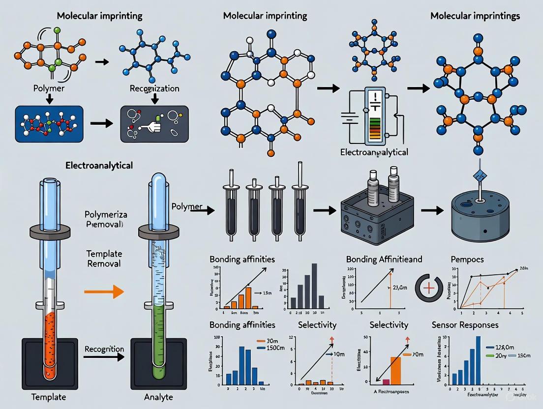
The following diagram illustrates the generalized workflow for the creation of a molecularly imprinted polymer, with emphasis on the non-covalent approach.
Diagram 1: General MIP synthesis and application workflow.
Advanced Considerations: Electric Field-Assisted Imprinting
Recent advancements aim to overcome traditional MIT challenges, such as heterogeneous binding sites and incomplete template removal. Electric field-assisted imprinting has emerged as a powerful strategy, particularly for fabricating electrochemical sensors [6].
During synthesis, an external electric field can orient polar template and monomer molecules, leading to a more uniform distribution and optimal alignment of binding sites. During the analytical application, the electric field can enhance mass transfer of the target analyte to the MIP-modified electrode surface, significantly improving the sensor's response speed and sensitivity [6]. The diagram below outlines the mechanisms of electric field assistance.
Diagram 2: Benefits of electric field assistance in MIP lifecycle.
Experimental Protocol: MIP-Modified Electrochemical Sensor for Pregabalin
This protocol details the synthesis of a highly selective MIP-based electrochemical sensor for the detection of Pregabalin (PGB), adapted from a recent study [4]. The sensor integrates a Copper Metal-Organic Framework (Cu-MOF) to enhance surface area and electrocatalytic activity.
Research Reagent Solutions
Table 2: Essential Materials and Reagents
| Reagent/Material | Function/Description | Supplier Example |
|---|---|---|
| Pregabalin (PGB) | Template molecule | Sigma-Aldrich or Merck |
| Ortho-Phenylenediamine (o-PD) | Functional monomer for electropolymerization | Sigma-Aldrich |
| Copper(II) Acetate Monohydrate | Metal precursor for Cu-MOF synthesis | Sigma-Aldrich |
| 4-Aminobenzoic Acid | Organic ligand for Cu-MOF synthesis | Sigma-Aldrich |
| Graphite Powder & Paraffin Oil | Components for Carbon Paste Electrode (CPE) | Sigma-Aldrich |
| Phosphate Buffered Saline (PBS) 0.1 M, pH 7.0 | Supporting electrolyte for electrochemical measurements | Prepared in-lab |
| Solvents (Ethanol, Water) | Porogen and cleaning | N/A |
Step-by-Step Procedure
Part A: Synthesis of Cu-MOF
- Dissolve 249.5 mg of Copper(II) acetate monohydrate and 42.0 mg of 4-aminobenzoic acid in a suitable solvent (e.g., ethanol/water mixture) [4].
- Allow the reaction to proceed under coprecipitation conditions, then collect the resulting Cu-MOF crystals via centrifugation.
- Wash the crystals thoroughly with the solvent and dry under vacuum.
Part B: Fabrication of MIP-Modified Sensor
- Prepare Cu-MOF/CPE: Mix graphite powder uniformly with the synthesized Cu-MOF (e.g., 95:5 w/w%). Incorporate paraffin oil to form a homogeneous paste. Pack the paste into an electrode body (e.g., 3.5 mm diameter) and smooth the surface.
- Electropolymerization (Critical Step for MIP formation):
- Prepare a polymerization solution containing 2.0 mM PGB (template) and 4.0 mM o-PD (monomer) in 0.1 M PBS (pH 7.0).
- Place the Cu-MOF/CPE in the solution along with Pt counter and Ag/AgCl reference electrodes.
- Using Cyclic Voltammetry (CV), scan the potential between -0.5 V and +0.8 V for 15 cycles at a scan rate of 50 mV/s. This deposits a thin, PGB-imprinted poly(o-PD) film on the electrode.
- Template Removal: Gently rinse the electrode and transfer it to a clean electrochemical cell containing only 0.1 M PBS (pH 7.0). Perform CV scans over a suitable potential range (e.g., 0.0 to +0.8 V) until a stable voltammogram is obtained, indicating complete extraction of the PGB template. The sensor (Cu-MOF/MIP-POPD/CPE) is now ready for use.
Part C: Electrochemical Measurement and Analysis
- Rebinding: Incubate the MIP-sensor in a sample solution containing an unknown concentration of PGB for a fixed time (e.g., 10-15 minutes) to allow selective rebinding.
- Detection: Using Differential Pulse Voltammetry (DPV), record the electrochemical signal in a clean 0.1 M PBS solution. The change in current (typically a decrease due to the insulating properties of the bound PGB) is proportional to the concentration.
- Quantification: Construct a calibration curve by plotting the DPV response versus the logarithm of known PGB concentrations. The sensor from the source study exhibited linear ranges of 0.003–0.09 µM, 0.1–1 µM, and 1–90 µM with a detection limit of 1.2 nM [4].
Application in Pharmaceutical Electroanalysis
The primary application of MIPs in the context of this thesis is as the recognition element in electrochemical sensors for therapeutic drug monitoring (TDM). A notable example is an electrochemical microfluidic chip integrated with an MIP for the trace measurement of drugs like warfarin sodium, cyclophosphamide, and carbamazepine [7]. This system demonstrated a remarkably low detection limit of 8 × 10⁻¹² M for warfarin, sufficient for monitoring drug levels in plasma [7]. The "gate effect" mechanism, where binding of the target analyte modulates the permeability of the polymer film, is often responsible for the high sensitivity of such MIP-based sensors.
Molecular imprinting creates robust, synthetic receptors with exceptional selectivity for target analytes. When combined with electrochemical transducers and advanced materials like MOFs, MIPs form the basis for highly sensitive, specific, and cost-effective sensors. The protocol outlined herein for pregabalin provides a template that can be adapted for the analysis of a wide range of pharmaceutical compounds, supporting advanced research in drug development and clinical monitoring.
Molecularly Imprinted Polymers (MIPs) are synthetic materials designed to mimic the molecular recognition capabilities of natural biological receptors, such as antibodies and enzymes [8]. These artificially generated receptors are created through the template-induced formation of specific recognition sites within a polymer matrix [9]. The resulting materials possess a unique combination of properties including robustness, high affinity, specificity, and low-cost production, making them attractive alternatives to natural receptors in electroanalytical applications [9] [10]. Over the past few decades, MIPs have evolved from scientific curiosities to viable sensing elements that can circumvent the limitations of their biological counterparts, particularly in the demanding environment of pharmaceutical analysis [10] [8].
The fundamental principle behind molecular imprinting involves the formation of complementary cavities in a polymer network that match the template molecule in size, shape, and chemical functionality [10]. This process, often compared to the Fischer's lock and key analogy for enzyme-substrate interactions, creates artificial recognition sites capable of selectively rebinding target analytes even in complex matrices [8]. Subsequent advancements in polymer science and nanotechnology have further enhanced MIP performance, driving their application in medical and forensic diagnostics [9].
Within pharmaceutical research, electrochemical biosensors represent powerful tools for detecting clinically relevant biomolecules, offering sensitive and specific detection accompanied by rapid response, user-friendly operation, portability, and real-time analysis [10]. The integration of MIPs as recognition elements in these sensing platforms has significantly expanded their capabilities for monitoring drugs, antibiotics, and biomarkers in various sample types [11] [12].
Comparative Advantages of MIPs Over Biological Receptors
The replacement of natural receptors with MIPs in electroanalytical systems addresses several critical limitations associated with biological recognition elements. While natural antibodies exhibit exceptional specificity, their practical implementation in sensors is constrained by instability under harsh environmental conditions, expensive synthesis procedures, and limited durability [10]. MIPs offer a compelling alternative with distinct advantages for pharmaceutical electroanalysis.
Table 1: Comparative Analysis of MIPs versus Biological Antibodies in Electroanalytical Applications
| Characteristic | Molecularly Imprinted Polymers (MIPs) | Biological Antibodies |
|---|---|---|
| Stability | High physicochemical stability; stable under harsh conditions (extreme pH, temperature, organic solvents) [10] | Limited stability; require strict physiological conditions [10] [13] |
| Production Cost & Shelf Life | Low-cost production; simple synthesis; long shelf life [9] [10] | Expensive and time-consuming production; limited shelf life [10] |
| Production Time | Relatively rapid preparation [10] | Lengthy in vivo or in vitro production [10] |
| Versatility | Compatible with various solvents and extreme conditions; wide range of possible templates [10] [8] | Primarily restricted to aqueous media and mild conditions [13] |
| Reusability | Reusable and durable in most cases [10] | Often limited to single-use [10] |
The superior stability of MIPs is particularly valuable for pharmaceutical analysis where sensors may encounter diverse sample matrices or require extended deployment. Their robustness under non-physiological conditions enables applications across wider pH and temperature ranges than possible with biological receptors [8]. Furthermore, the simplicity of their production makes specific recognition units more readily available compared to relying on antibody production, which often involves animal hosts or complex cell cultures [10].
The versatility of possible templates allows MIPs to be developed for recognition and rebinding of challenging analytes, including small molecules, proteins, and even viruses or microorganisms [10] [8]. This flexibility, combined with their ease of adaptation to various biomedical applications, positions MIPs as transformative elements in separation technologies, diagnostics, (bio)sensing, and drug delivery [10].
MIP Synthesis and Integration Methods
The creation of effective molecularly imprinted polymers involves multiple synthesis approaches, each with distinct advantages for particular applications. The fundamental process encompasses three key steps: (1) pre-assembly of functional monomers around a template molecule, (2) polymerization to form a cross-linked network, and (3) template removal to create specific recognition cavities [10].
Synthesis Approaches
Table 2: Common Molecular Imprinting Methods for Electrochemical Sensors
| Imprinting Method | Key Features | Best For |
|---|---|---|
| Bulk Imprinting | Pre-polymer mixture coats transducer surface; template entrapped during curing; removed via elution [10] | Small molecule templates; general purpose applications |
| Surface Imprinting | Requires support material; binding sites positioned near polymer surface; creates thin polymer films [10] | Protein imprinting; improved accessibility to binding sites |
| Electropolymerization | Electrochemical energy initiates polymerization; precise film thickness control; direct transducer modification [13] | Integrated sensor development; controlled thin-film formation |
The selection of appropriate functional monomers and cross-linkers is crucial for creating high-affinity binding sites. In covalent imprinting, developed by Wulff and Sarhan, template molecules are connected to functional monomers through reversible covalent bonds, providing excellent control over binding site uniformity [8]. Alternatively, non-covalent imprinting, pioneered by Mosbach et al., relies on self-assembly through hydrogen bonding, ionic interactions, or hydrophobic effects between template and monomers, offering greater flexibility and simpler preparation [10] [8].
For electrochemical sensors specifically, electropolymerization has emerged as a particularly valuable synthesis method. This approach enables direct formation of MIP films on electrode surfaces through application of controlled potential or current, allowing precise control over film thickness and morphology [13]. The resulting electropolymerized MIPs (e-MIPs) are especially suitable for miniaturized sensors and point-of-care devices [13].
The Scientist's Toolkit: Essential Materials for MIP Development
Table 3: Key Research Reagent Solutions for MIP-Based Electroanalysis
| Reagent/Material | Function/Purpose | Examples/Notes |
|---|---|---|
| Functional Monomers | Provide complementary chemical groups for template binding | Acrylic acid, methacrylic acid, vinylpyridine [8] |
| Cross-linkers | Create rigid 3D polymer network around template | Ethylene glycol dimethacrylate (EGDMA), divinylbenzene [8] |
| Initiators | Begin polymerization reaction under specific conditions | Azobisisobutyronitrile (AIBN, thermal), riboflavin (photochemical) [8] |
| Nanomaterials | Enhance sensor sensitivity and surface area | MWCNTs, graphene, gold nanoparticles, quantum dots [13] |
| Electrode Materials | Serve as transduction platform for signal measurement | Glassy carbon, carbon paste, screen-printed electrodes [12] [14] |
The integration of nanomaterials has been particularly transformative for MIP-based sensors, with nanoparticles, multiwalled carbon nanotubes, quantum dots, and graphene structures significantly enhancing sensitivity and electrical properties [13]. These nanocomposites address the inherently poor electrical conductivity of traditional MIPs, improving electron transfer kinetics and overall sensor performance [13] [14].
Experimental Protocols
Protocol: Development of Electropolymerized MIP (e-MIP) Sensor for Pharmaceutical Compounds
Objective: To create an electropolymerized molecularly imprinted polymer sensor for selective detection of target pharmaceuticals in complex samples.
Materials and Equipment:
- Electrochemical workstation with potentiostat
- Three-electrode system: Working electrode (glassy carbon, gold, or screen-printed), reference electrode (Ag/AgCl), counter electrode (platinum wire)
- Template molecule (target pharmaceutical)
- Functional monomers (e.g., o-phenylenediamine, pyrrole, aniline)
- Supporting electrolyte (e.g., phosphate buffer, acetate buffer)
- Nanomaterials (e.g., graphene oxide, multiwalled carbon nanotubes) for electrode modification
- Solvents for template removal (e.g., methanol:acetic acid mixtures)
Procedure:
Electrode Pretreatment:
- Polish working electrode with alumina slurry (0.3 µm and 0.05 µm) on microcloth
- Rinse thoroughly with deionized water between polishing steps
- Clean via electrochemical cycling in 0.5 M H₂SO₄ until stable cyclic voltammogram obtained
Nanomaterial Modification (Optional Enhancement):
- Prepare dispersion of nanomaterial (e.g., 1 mg/mL graphene oxide in DMF)
- Deposit predetermined volume onto electrode surface
- Allow to dry under infrared lamp or at controlled temperature
Electropolymerization Solution Preparation:
- Prepare solution containing template molecule (2-10 mM) and functional monomer (20-100 mM) in selected supporting electrolyte
- Degas with nitrogen or argon for 5-10 minutes to remove oxygen
Polymerization via Cyclic Voltammetry:
- Immerse electrode system in polymerization solution
- Apply cyclic voltammetry between predetermined potential limits (e.g., -0.5 to +0.8 V vs. Ag/AgCl)
- Complete 10-30 cycles at scan rate of 50 mV/s
- Monitor current decrease with successive cycles, indicating polymer film growth
Template Removal:
- Transfer modified electrode to clean supporting electrolyte without template
- Apply electrochemical overpotential or cyclic voltammetry in different potential window
- Alternatively, use solvent extraction with methanol:acetic acid (9:1 v/v) with gentle stirring
- Confirm template removal by stabilization of electrochemical signal
Rebinding Studies and Sensor Characterization:
- Expose MIP-modified electrode to standard solutions of template at varying concentrations
- Incubate for predetermined time (5-15 minutes) with gentle stirring
- Measure electrochemical response using differential pulse voltammetry, square wave voltammetry, or electrochemical impedance spectroscopy
- Compare with non-imprinted polymer (NIP) control to determine imprinting factor
Validation:
- Determine linear range, detection limit, and quantification limit using standard additions
- Evaluate selectivity against structurally similar compounds
- Assess reproducibility through multiple sensor preparations
- Test stability over time with proper storage conditions
Protocol: MIP-Modified Carbon Paste Electrode (MIP-CPE) for Drug Analysis
Objective: To prepare a carbon paste electrode modified with molecularly imprinted polymers for sensitive determination of pharmaceutical compounds.
Materials and Equipment:
- Graphite powder
- Mineral oil or paraffin as binding agent
- Pre-synthesized MIP particles (prepared via bulk polymerization)
- Mortar and pestle for mixing
- Electrode body for paste packing
- Ag/AgCl reference electrode and platinum counter electrode
Procedure:
MIP Synthesis via Bulk Polymerization:
- Dissolve template (target drug, 0.5-1 mmol), functional monomer (2-4 mmol), and cross-linker (10-20 mmol) in porogenic solvent
- Add radical initiator (e.g., AIBN, 1% w/w)
- Purge with nitrogen or argon for 5 minutes to remove oxygen
- Seal and polymerize at 60°C for 12-24 hours
- Grind resulting polymer and sieve to desired particle size (25-50 µm)
- Extract template thoroughly using Soxhlet extraction or repeated washing
- Dry under vacuum at 40-60°C
Carbon Paste Preparation:
- Mix graphite powder and MIP particles in predetermined ratio (typical MIP content: 10-20% w/w)
- Add mineral oil (typically 30-40% w/w of total paste)
- Blend thoroughly in mortar until homogeneous paste obtained
- For control electrode, prepare NIP-modified carbon paste following same procedure
Electrode Assembly:
- Pack paste firmly into electrode cavity
- Smooth surface against weighing paper or similar smooth surface
- Electrical contact established through plunger mechanism
Measurement Procedure:
- Pre-condition electrode by cycling in clean supporting electrolyte
- Incubate in sample solution with stirring for predetermined accumulation time
- Transfer to electrochemical cell with clean supporting electrolyte
- Apply appropriate voltammetric technique for quantification
- Renew electrode surface by gently pushing out small amount of paste and polishing on smooth paper
Applications: This approach has been successfully applied for determination of analgesic drugs, antibiotics, antivirals, cardiovascular drugs, and therapeutic agents affecting the central nervous system [12].
Applications in Pharmaceutical Electroanalysis
The implementation of MIP-based sensors has demonstrated significant utility across diverse pharmaceutical analysis scenarios, particularly for compounds where traditional analytical methods face limitations.
Antibiotic Monitoring
MIP sensors have been extensively developed for antibiotic determination in environmental, food, and biological matrices [11]. The electrochemical detection of antibiotics is crucial for preventing antibiotic resistance development and ensuring food safety. Published works have covered the electroanalysis of a wide range of different antibiotic classes, including β-lactams, tetracyclines, quinolones, macrolides, and aminoglycosides [11]. Both electropolymerized MIPs and those developed by other polymerization techniques have been successfully applied, with approximately 60 publications and patents focusing on e-MIPs for antibiotic detection [11].
Biomarker Detection and Clinical Diagnostics
The detection of protein-based biomarkers represents a particularly challenging application area where MIPs offer distinct advantages. Unlike small molecular targets, proteins present special challenges due to their size, irreversible conformational changes, and complex structure [10]. Recent approaches in surface imprinting have enabled the development of MIP sensors capable of recognizing specific protein biomarkers, driving applications in medical diagnostics [10]. These sensors facilitate early disease detection and subsequent monitoring of disease progression through rapid, selective, and cost-effective detection of clinically relevant biomolecule analytes [10].
Comprehensive Pharmaceutical Analysis
MIP-modified electrodes have been created for various pharmaceutical compounds including analgesic drugs, antibiotics, antivirals, cardiovascular drugs, and therapeutic agents affecting the central nervous system [12]. The carbon paste electrode platform, modified with MIPs, has emerged as particularly promising due to beneficial properties including ease of electrode modification, facile surface renewability, low background currents, and versatile modification capabilities [12]. This approach addresses the lack of sufficient selectivity of traditional carbon paste electrodes while maintaining their practical advantages.
Molecularly Imprinted Polymers represent a transformative technology in pharmaceutical electroanalysis, offering robust artificial antibodies that overcome the limitations of biological receptors. Their superior stability, cost-effectiveness, and versatility position them as ideal recognition elements for electrochemical sensors targeting pharmaceutical compounds, biomarkers, and environmental contaminants [9] [10]. The continued advancement of MIP technology, particularly through integration with nanomaterials and improved synthesis methodologies, promises further enhancements in sensitivity and selectivity [13] [14].
Future perspectives for MIP-based sensors include increased adoption of lab-on-a-chip systems, integration with artificial intelligence for data interpretation, and development of commercial platforms for point-of-care testing [15]. These advancements will solidify the role of MIPs as indispensable tools in modern pharmaceutical research, quality control, and clinical diagnostics, ultimately contributing to more efficient drug development and improved patient outcomes.
Molecularly Imprinted Polymers (MIPs) are synthetic polymeric materials engineered to possess specific recognition sites for a target molecule, known as the template. Their function as "artificial receptors" or "plastic antibodies" makes them particularly valuable in electroanalysis, where they provide the critical selectivity needed for detecting pharmaceuticals in complex matrices [16] [17]. The fundamental principle of molecular imprinting involves the polymerization of functional monomers and cross-linkers around a template molecule. Subsequent removal of the template leaves behind cavities that are complementary in size, shape, and chemical functionality, enabling the MIP to selectively rebind the target analyte [18] [2]. The advantages of MIPs—including high physical and chemical robustness, cost-effectiveness, resistance to harsh conditions, and long shelf life—make them superior to natural biological receptors for many analytical applications, particularly in the development of stable and reusable electrochemical sensors [18] [17] [11].
Core Components of MIPs
The successful development of a MIP relies on the careful selection and combination of four key components. The interactions between these components determine the affinity, selectivity, and overall performance of the final polymer.
Template Molecules
The template is the target molecule around which the complementary binding site is created. In pharmaceutical electroanalysis, the template is typically the drug molecule or a structural analogue that needs to be detected [19].
- Selection Criteria: The ideal template should be chemically stable under polymerization conditions, possess functional groups capable of interacting with monomers, and be available in sufficient purity [19].
- Single vs. Multiple Templates: While single-template MIPs (ST-MIPs) are highly selective for one analyte, multi-template MIPs (MT-MIPs) can be synthesized for the simultaneous recognition of several analytes. The MT-MIP strategy offers significant advantages for multi-analyte sensing, including reduced solvent consumption, cost-effectiveness, and shorter analysis time [19].
Functional Monomers
Functional monomers are the cornerstone of molecular recognition. They contain functional groups that interact with the template molecule via non-covalent (e.g., hydrogen bonding, ionic interactions, van der Waals forces) or covalent bonds to form a complex prior to polymerization [18] [16]. The choice of monomer is paramount for creating high-affinity binding sites.
Table 1: Common Functional Monomers and Their Applications
| Monomer | Chemical Nature | Primary Interaction with Template | Exemplary Template in Pharmaceuticals |
|---|---|---|---|
| Methacrylic Acid (MAA) | Acidic | Hydrogen bonding, Ionic | Ametryn (Herbicide) [20], Antibiotics [11] |
| Acrylamide (AAm) | Neutral | Hydrogen bonding | Histamine [21] |
| 2-Vinylpyridine (2-VP) / 4-Vinylpyridine (4-VP) | Basic | Hydrogen bonding, Ionic | Drugs [19] |
Advances in monomer selection now heavily utilize computational simulation to screen large databases of monomers and predict the strength and nature of monomer-template interactions before embarking on resource-intensive laboratory synthesis [16] [22].
Cross-linkers
Cross-linkers are multifunctional molecules that create a rigid, three-dimensional polymer network around the template-monomer complex. This network stabilizes the binding sites and maintains their structural integrity after the template is removed [2] [21].
- Functions: The cross-linker controls the polymer morphology, stabilizes the imprinted binding site, and imparts mechanical stability to the polymer matrix [2].
- Common Cross-linkers: Ethylene Glycol Dimethacrylate (EGDMA) is one of the most widely used cross-linkers in non-covalent imprinting [19] [20]. Others include divinylbenzene (DVB) and N,N'-methylenebisacrylamide (BIS) [19] [21].
- Cross-linker Optimization: The type and amount of cross-linker are critical. While a high degree of cross-linking provides rigidity, some flexibility can be beneficial for rebinding. A systematic study on polyacrylamide-based MIPs found that a cross-linker with a four-methylene spacer (BA4) offered an optimal balance, leading to high binding capacity and selectivity for histamine [21].
Polymerization Methods and Initiators
Polymerization is the process of forming the highly cross-linked polymer. The method chosen determines the physical format and properties of the MIP, which are crucial for its integration into electrochemical sensors.
Table 2: Common Polymerization Methods for MIP Synthesis
| Method | Procedure | Advantages | Disadvantages | Suitability for Electroanalytical Sensors |
|---|---|---|---|---|
| Bulk Polymerization | Polymerization in a monolithic block, followed by grinding and sieving [19]. | Simple, universal method [19]. | Irregular particle shapes, heterogeneous binding sites, potential damage to cavities during grinding [19]. | Moderate; irregular particles can be mixed into carbon paste electrodes (CPEs) [12]. |
| Precipitation Polymerization | Polymerization in a dilute solution where the polymer becomes insoluble and precipitates [19] [20]. | Produces spherical, monodisperse particles in a one-step process [19] [20]. | Requires large amounts of solvent and template [19]. | High; spherical particles are ideal for creating uniform modified electrodes [20]. |
| Electropolymerization | Monomers are directly polymerized onto an electrode surface by applying a potential [11]. | Direct formation of thin, homogeneous MIP films on the transducer surface; excellent control over film thickness [11]. | Limited to electroactive monomers. | Very High; the preferred method for fabricating sensitive and reproducible electrochemical sensors [11]. |
Polymerization is typically initiated by thermal decomposition or photoactivation of an initiator, such as azobis(isobutyronitrile) (AIBN), which generates free radicals to start the chain reaction [19] [20].
Experimental Protocols
Protocol 1: Synthesis of MIP Microspheres via Precipitation Polymerization for Sensor Application
This protocol outlines the synthesis of MIP microspheres using ametryn as a template, which can subsequently be incorporated into a carbon paste electrode for electrochemical detection [20].
Materials:
- Template: Ametryn (AME)
- Functional Monomers: Methacrylic acid (MAA), Acrylamide (AAm), or 2-Vinylpyridine (2-VP)
- Cross-linker: Ethylene glycol dimethacrylate (EGDMA)
- Initiator: Azobis(isobutyronitrile) (AIBN)
- Porogenic solvent: Toluene
- Washing solvent: Methanol/Acetic acid (6:4, v/v)
Procedure:
- In a 250 mL conical flask, combine 1.0 mmol of AME, 5.0 mmol of a functional monomer (e.g., MAA), 20.0 mmol of EGDMA, and 30 mg of AIBN in 100 mL of toluene.
- Sonicate the mixture for 10 minutes to ensure complete dissolution and degas with nitrogen gas for 15 minutes in an ice-water bath to remove oxygen.
- Seal the flask tightly and place it in a water bath at 80 °C for 6 hours to complete the polymerization reaction.
- After polymerization, collect the polymer particles by centrifugation (e.g., 4000 rpm for 15 min) and dry at room temperature.
- Extract the template by continuously washing the polymer with the methanol/acetic acid solution until the template can no longer be detected in the washings by UV-Vis spectroscopy.
- Finally, rinse the polymers with pure methanol to remove residual acetic acid and dry at room temperature.
- For electrochemical application, the synthesized MIP microspheres are mixed with graphite powder and a binder (e.g., paraffin oil) to fabricate a modified carbon paste electrode (MIP-CPE) [12].
Protocol 2: Investigating Cross-linker Effects on MIP Performance
This protocol describes a method to systematically study the impact of cross-linker flexibility on MIP adsorption properties, as demonstrated for histamine imprinting [21].
Materials:
- Functional Monomer: Acrylamide (AAm)
- Cross-linkers: N,N'-Polymethylenebis(acrylamide) with spacer lengths of 1, 2, 4, and 6 methylenes (BA1, BA2, BA4, BA6).
- Template: Histamine (HA)
- Other reagents: Initiator (e.g., AIBN), porogen, silica support for surface imprinting.
Procedure:
- Synthesize a series of MIPs using the same template (HA), functional monomer (AAm), and polymerization method, but vary the cross-linker (BA1, BA2, BA4, BA6). Synthesize corresponding Non-Imprinted Polymers (NIPs) without the template for each cross-linker.
- Characterize the polymers using techniques like BET surface area analysis and FT-IR.
- Perform batch rebinding experiments: incubate a fixed amount of each MIP (e.g., 10 mg) with a solution of HA (e.g., 20 mL of a 50 mg L⁻¹ solution) at room temperature.
- Measure the concentration of HA in the solution at various time intervals using a suitable analytical method (e.g., HPLC-UV) to establish adsorption kinetics.
- Determine the binding capacity (Q, mg g⁻¹) for each MIP and its corresponding NIP.
- Calculate the Imprinting Factor (IF) for each cross-linker: IF = QMIP / QNIP.
- Conduct competitive adsorption assays with structurally similar interfering substances (e.g., tyramine, melamine) to evaluate selectivity.
Expected Outcome: The study by Boukadida et al. found that the cross-linker BA4 (with a 4-methylene spacer) provided the optimum binding capacity and selectivity, demonstrating that a degree of flexibility can be more beneficial than extreme rigidity [21].
The Scientist's Toolkit: Essential Research Reagents
Table 3: Key Reagents for MIP Development and Fabrication
| Reagent Category & Examples | Function in MIP Development |
|---|---|
| Functional Monomers (Methacrylic Acid, Acrylamide, 4-Vinylpyridine) | To provide functional groups for interaction with the template, forming a pre-polymerization complex [18] [20]. |
| Cross-linkers (EGDMA, N,N'-methylenebisacrylamide) | To create a rigid, porous polymer network that stabilizes the shape and position of the imprinted cavities [19] [21]. |
| Initiators (AIBN, Potassium Persulfate) | To generate free radicals and initiate the polymerization reaction, either thermally or photochemically [19] [20]. |
| Porogenic Solvents (Toluene, Acetonitrile, Chloroform) | To dissolve all components and create the pore structure within the polymer during synthesis [19] [20]. |
| Graphite Powder & Paste Binder (Paraffin Oil) | To form the conductive carbon paste matrix for embedding synthesized MIP particles to create an electrochemical sensor [12]. |
Workflow and Signaling Visualization
The following diagram illustrates the comprehensive workflow for the development and application of a Molecularly Imprinted Polymer for electrochemical pharmaceutical analysis, integrating the key components and protocols discussed.
The development of Molecularly Imprinted Polymers (MIPs) has been transformed by the integration of theoretical and computational approaches. These tools provide atomistic insights into the molecular recognition processes fundamental to MIP function, moving development from empirically-guided to rationally-designed synthesis [23]. Within pharmaceutical electroanalysis, this paradigm shift enables the creation of highly selective biomimetic sensors for monitoring drugs, metabolites, and emerging contaminants with unprecedented efficiency [11] [15]. Computational methods are now employed to study all stages of the molecular imprinting process—from the pre-polymerization mixture and polymerization process to ligand-MIP rebinding—thereby accelerating the design of robust analytical platforms [23].
Theoretical and Computational Foundations
Thermodynamic Principles of Molecular Imprinting
The recognition properties of MIPs are fundamentally governed by the thermodynamics of the pre-polymerization mixture. The formation of template-functional monomer complexes is an equilibrium process dictated by the Gibbs free energy of binding (ΔGbind). A more favorable (negative) ΔGbind drives the equilibrium towards complex formation, leading to a larger number of high-fidelity binding sites in the final polymer [23].
The comprehensive thermodynamic treatment of this interaction, as detailed by Williams, factorizes ΔGbind into its constituent contributions [23]: ΔGbind = ΔGt+r + ΔGr + ΔGh + ΔGvib + ∑ΔGp + ΔGconf + ΔGvdW
Table: Components of Gibbs Free Energy in Molecular Imprinting
| Term | Description | Impact on MIP Design |
|---|---|---|
| ΔGt+r | Penalty from loss of translational/rotational freedom | Favors use of multi-dentate monomers over high concentrations of single-point monomers [23]. |
| ΔGr | Penalty from restriction of internal bond rotation | Favors rigid templates, which yield MIPs with higher selectivity and narrower site distribution [23]. |
| ∑ΔGp | Sum of interacting polar group contributions | In organic solvents, selectivity is driven by strong polar interactions (e.g., hydrogen bonds) [23]. |
| ΔGh | Contribution from hydrophobic interactions | In aqueous environments, hydrophobic effects can drive complexation [23]. |
Key Computational Strategies
The adoption of computational strategies has been crucial for navigating the complex, interdependent equilibria involved in MIP synthesis [23]. These methods have seen a significant increase in application over the past decade, driven by more accessible computational power and software [23].
Table: Computational Methods for MIP Development
| Method | Primary Application in MIP Development | Key Outputs |
|---|---|---|
| Electronic Structure Calculations (e.g., DFT) | Studying monomer-template interactions in the pre-polymerization phase [23]. | Binding energies, optimal binding geometries, interaction sites [24]. |
| Molecular Dynamics (MD) | Simulating the pre-polymerization mixture and polymer-ligand interactions, including the effects of solvent, cross-linkers, and initiators [23] [24]. | Stability of template-monomer complexes, simulation of polymer morphology and binding site heterogeneity [23]. |
| Molecular Mechanics | High-throughput virtual screening of large monomer databases against a template molecule [2]. | Ranking of functional monomers based on their computed affinity for the template [2]. |
| Multivariate Analysis | Optimizing polymer composition by simultaneously evaluating multiple synthesis variables [23]. | Identification of key factors influencing MIP performance and optimal synthesis conditions [23]. |
Application Notes: Computational Protocol for MIP-Based Sensor Design
This protocol outlines the computational design of a MIP for the detection of an antibiotic, followed by its integration into an electrochemical sensor, relevant for pharmaceutical quality control and environmental monitoring [11].
The following diagram illustrates the integrated computational and experimental workflow for developing a MIP-based electrochemical sensor.
Detailed Computational Methodology
Protocol 1: Virtual Screening and Pre-polymerization Analysis
Objective: To identify the most suitable functional monomer and solvent for creating a high-affinity MIP against a target pharmaceutical compound.
Materials & Software:
- Target Molecule: A 3D structure file of the pharmaceutical (e.g., an antibiotic like a quinolone or β-lactam).
- Software: Molecular modeling suite (e.g., GROMACS [24]), quantum chemistry software (for DFT), and visualization tool (e.g., UCSF Chimera [24]).
- Monomer Library: Digital libraries of common functional monomers (e.g., methacrylic acid, itaconic acid, vinylpyridine).
Procedure:
- Geometry Optimization: Optimize the 3D structure of the target molecule and all candidate monomers using density functional theory (DFT) methods to obtain their most stable conformations [23].
- Molecular Docking/Monomer Screening: Employ molecular mechanics or semi-empirical methods to screen the monomer library. Calculate the binding energy (ΔE) for each template-monomer complex. ΔE = E(template–monomer complex) – [E(template) + E(monomer)] A more negative ΔE indicates a stronger interaction [24] [2].
- MD Simulation of Pre-polymerization Mixture:
- Construct a simulation box containing the template, the top-ranked functional monomer(s) in a predetermined ratio (e.g., 1:4), cross-linker (e.g., EGDMA), and solvent molecules.
- Run an all-atom MD simulation for several nanoseconds to observe the stability of the template-monomer complexes under conditions mimicking the actual synthesis [23].
- Analyze the root-mean-square deviation (RMSD) of the complexes and the number of persistent hydrogen bonds or other key interactions over the simulation time. Stable complexes with multiple persistent interactions suggest a promising formulation [23].
- Solvent Selection: The solvent (porogen) should solubilize all components. Its polarity should complement the primary template-monomer interactions—low-polarity solvents enhance polar interactions, while water can leverage hydrophobic effects [23]. The choice can be guided by calculating the solvation free energy of the template and complexes in different solvents.
Experimental Validation and Sensor Fabrication
Protocol 2: MIP Synthesis and Electrochemical Sensor Fabrication
Objective: To synthesize the computationally designed MIP and integrate it into an electrochemical sensor for the detection of the target analyte.
Research Reagent Solutions:
Table: Essential Materials for MIP-based Sensor Development
| Reagent/Category | Function | Example(s) |
|---|---|---|
| Functional Monomer | Provides complementary chemical groups to interact with the template. | Methacrylic acid (hydrogen bonding), Vinylpyridine (ionic interactions) [2]. |
| Cross-linker | Stabilizes the imprinted cavities and provides mechanical rigidity to the polymer matrix. | Ethylene glycol dimethacrylate (EGDMA), Divinylbenzene (DVB) [25] [2]. |
| Polymerization Initiator | Generates free radicals to initiate the polymerization reaction. | Azobisisobutyronitrile (AIBN) [24] [2]. |
| Porogenic Solvent | Dissolves all components and creates pore structure during polymerization. | Acetonitrile, Dimethyl sulfoxide (DMSO), Chloroform [24]. |
| Electroactive Polymer | Used for electrosynthesis of MIPs; acts as both the matrix for imprinting and the conductive layer on the electrode. | Polypyrrole (Ppy), Polyaniline (PANI), Poly(3,4-ethylenedioxythiophene) (PEDOT) [25]. |
Procedure:
- MIP Synthesis (Bulk Polymerization):
- Dissolve the target analyte (template), selected functional monomer, cross-linker, and initiator (e.g., AIBN) in the porogenic solvent based on the computationally optimized ratios [24].
- Purge the solution with nitrogen or argon to remove oxygen, which inhibits free-radical polymerization.
- Initiate polymerization by heating or UV irradiation. For the melamine MIP case study, polymerization at 60°C with AIBN was optimal [24].
- After polymerization, grind the resulting polymer block and sieve it to obtain particles of desired size.
- Extract the template molecules using a suitable solvent (e.g., methanol:acetic acid mixture) until no template can be detected in the washings [2].
- Sensor Fabrication (Electropolymerization):
- Prepare a solution containing the template, electroactive monomer (e.g., pyrrole), and supporting electrolyte.
- Immerse the working electrode (e.g., glassy carbon, gold) in the solution.
- Deposit the MIP film by performing cyclic voltammetry (CV) or chronoamperometry by applying a suitable potential window or constant potential [25]. The film's properties can be tuned by varying the number of CV cycles, applied potential, or charge passed [25].
- Remove the template from the electropolymerized film by washing with an appropriate solvent, leaving behind specific recognition cavities [26].
- Electrochemical Detection:
- Incubate the MIP-modified electrode in a sample solution containing the target analyte to allow rebinding.
- After incubation and rinsing, transfer the electrode to a clean electrochemical cell containing only a supporting electrolyte.
- Perform a sensitive electrochemical technique such as Differential Pulse Voltammetry (DPV) or Square Wave Voltammetry (SWV). These techniques minimize capacitive background current, enhancing the sensitivity for detecting the bound electroactive analyte [11] [15]. The oxidation/reduction peak current is proportional to the concentration of the bound analyte.
Case Study: Computational Design of a Melamine-Imprinted Polymer
A representative study demonstrates the power of this integrated approach. Researchers developed a MIP for melamine detection using computational tools to accelerate the design process [24].
Computational Design: The team used the GROMACS molecular simulation suite to determine the ideal stoichiometric ratio between the melamine template and the functional monomer, itaconic acid. The simulations confirmed the formation of strong hydrogen bonds, which was the basis for the high specificity [24].
Experimental Validation: The polymer was synthesized using DVB as a cross-linker and itaconic acid as the monomer in dimethyl sulfoxide (DMSO). The resulting MIP exhibited an imprinting factor (IF) of 2.25, indicating successful creation of specific binding sites. This MIP was successfully deployed in an HPLC system for the rapid detection of melamine in spiked milk samples, with each run taking only 7-8 minutes [24]. This case highlights how computational modeling can reduce experimental trial time and optimize the final polymer's performance.
Computational design and quantum mechanical modeling have fundamentally changed the landscape of MIP development. By providing deep insights into the thermodynamic and molecular forces at play, these tools enable the rational design of synthetic receptors with predetermined recognition properties [23]. When this rational design is coupled with the simplicity, sensitivity, and portability of electrochemical transducers, it creates a powerful platform for pharmaceutical analysis [11] [15]. The continued integration of advanced simulations, multivariate analysis, and nanotechnology promises to further enhance the sensitivity and specificity of MIP-based sensors, solidifying their role as indispensable tools in drug development, therapeutic monitoring, and environmental safety [15].
Fabrication and Applications: Building Next-Generation Electrochemical MIP-Sensors for Pharmaceuticals
Electropolymerization Techniques for MIP Film Synthesis on Electrode Surfaces
Molecularly Imprinted Polymers (MIPs) are synthetic biomimetic receptors that possess specific recognition sites for target molecules, complementing them in size, shape, and functional groups [27]. The integration of MIPs with electrochemical transducers creates robust sensors highly suitable for pharmaceutical analysis, offering advantages over biological receptors including superior stability, lower cost, and longer shelf life [28] [29]. Electropolymerization has emerged as a highly effective method for synthesizing MIP films directly on electrode surfaces, enabling precise control over film properties and ensuring excellent reproducibility [28] [30]. This protocol details the application of electropolymerization for MIP-based sensor development within pharmaceutical electroanalysis.
Fundamental Principles of MIP Electropolymerization
Electropolymerization involves the voltage- or current-induced oxidation of polymerizable monomers, leading to the formation of a polymeric film on the working electrode surface [28]. This method allows for in-situ synthesis of the MIP recognition layer directly on the transducer. During the process, functional monomers are organized around the template molecule (the pharmaceutical target). Subsequent polymerization, in the presence of a cross-linker, "freezes" this structure, and template removal creates specific recognition cavities within the polymer matrix [27].
A key advantage of electropolymerization is the fine control it offers over film thickness by adjusting the total charge passed during deposition [28] [31]. This is particularly crucial for macromolecular imprinting to prevent irreversible template entrapment and to facilitate mass transfer [32]. The method is compatible with aqueous solutions and room temperature operation, preserving the structural integrity of biomacromolecule templates [33]. Commonly used electropolymerizable monomers include pyrrole, aniline, o-phenylenediamine (o-PD), 3-aminophenylboronic acid (APBA), and scopoletin [28].
Experimental Protocols
Protocol 1: Bulk Imprinting via Electropolymerization
This standard one-pot procedure is suitable for imprinting small molecule pharmaceuticals.
- Step 1: Pre-polymerization Solution Preparation. Dissolve the template molecule (e.g., 0.5-5 mM), functional monomer (e.g., 10-50 mM), and cross-linker (if applicable) in a suitable solvent or electrolyte (e.g., phosphate buffer, acetonitrile). The monomer-to-template ratio should be optimized computationally or empirically [28].
- Step 2: Electrode Pretreatment. Clean the working electrode (e.g., Glassy Carbon Electrode, GCE; or Gold Electrode) according to standard procedures (e.g., polishing with alumina slurry, sonicating in water and ethanol, and electrochemical cycling in a clean solution) [34].
- Step 3: Film Deposition. Immerse the pretreated working electrode in the pre-polymerization solution. Perform electropolymerization using a potentiodynamic (e.g., Cyclic Voltammetry, CV, for 5-20 cycles) or galvanostatic method. Control the film thickness by regulating the number of cycles or the total charge passed [31].
- Step 4: Template Removal. Remove the MIP-modified electrode from the polymerization solution and rinse it gently. Extract the template molecules by immersing the electrode in a suitable elution solvent (e.g., methanol-acetic acid mixture) under stirring for 10-30 minutes. Repeat the washing until no template is detected in the washings [35].
- Step 5: Sensor Validation. Characterize the MIP film electrochemically using a redox probe like [Fe(CN)₆]³⁻/⁴⁻ via CV or Electrochemical Impedance Spectroscopy (EIS) to confirm successful template removal and cavity formation [33].
Protocol 2: Surface Imprinting with Covalent Template Immobilization
This advanced protocol is designed for proteins and macromolecules, confining binding sites to the surface for improved accessibility [32] [28].
- Step 1: Electrode Functionalization. For a gold electrode, incubate it in a solution of a self-assembled monolayer (SAM) forming molecule (e.g., 4-aminothiophenol) for several hours. Rinse thoroughly. Then, activate the terminal amino groups by reacting with a bifunctional linker like glutaraldehyde [33] [32].
- Step 2: Template Immobilization. Incubate the functionalized electrode in a solution of the protein template (e.g., lysozyme) to allow for covalent immobilization via the linker. Rinse rigorously to remove physically adsorbed molecules [33] [28].
- Step 3: Electropolymerization. Perform electropolymerization from a solution containing the monomer(s) but no free template. Carefully control the polymerization charge to form an ultrathin film that partially embeds the surface-bound protein [32].
- Step 4: Linker Cleavage and Template Extraction. Cleave the covalent linker (e.g., by chemical or electrochemical means) to release the template protein, leaving behind surface-exposed, highly specific cavities [28].
- Step 5: Binding Assay. Evaluate the binding performance and selectivity of the sensor using impedimetric or voltammetric techniques [33].
Performance Comparison of Electropolymerized MIP Sensors
Table 1: Analytical performance of selected electropolymerized MIP sensors for different analytes.
| Target Analyte | Monomer Used | Linear Range | Limit of Detection (LOD) | Reference Application |
|---|---|---|---|---|
| Lysozyme (Protein) | Scopoletin | 2.2 - 292 mg/L | 0.9 mg/L (62 nM) | [33] |
| Peramivir (Drug) | 4-AP / o-PD | 1 - 10 pM | 0.158 pM | [34] |
| 17β-Estradiol | 0.5 - 100 nM | 0.12 nM | [36] |
The Scientist's Toolkit: Essential Research Reagents
Table 2: Key reagents and materials for MIP electropolymerization.
| Reagent/Material | Function/Explanation | Common Examples |
|---|---|---|
| Functional Monomers | Polymerizable units that interact with the template, forming the basis of the recognition cavity. | Pyrrole, aniline, o-phenylenediamine (o-PD), scopoletin, 3-aminophenylboronic acid (APBA) [28] [30]. |
| Cross-linkers | Agents that create a rigid 3D polymer network, stabilizing the imprinted cavities. | Often inherent in electropolymerization, but can be added (e.g., ethylene glycol dimethacrylate - EGDMA in some schemes) [35]. |
| Electrochemical Cell | Setup for performing electropolymerization and subsequent electrochemical measurements. | Three-electrode system: Working Electrode (GCE, Au), Reference Electrode (Ag/AgCl), Counter Electrode (Pt wire) [34]. |
| Template Molecules | The target molecules around which the polymer is formed, creating specific binding sites. | The pharmaceutical compound of interest (e.g., Peramivir, Lysozyme) or a structural analog [33] [34]. |
| Elution Solvent | A solution used to remove the template molecule from the polymerized film, revealing the cavities. | Methanol:acetic acid mixtures, or other solvents that disrupt template-monomer interactions without damaging the polymer [35]. |
| Redox Probe | An electroactive marker used to characterize the MIP film and transduce the binding event. | Potassium ferricyanide/ferrocyanide ([Fe(CN)₆]³⁻/⁴⁻) is commonly used in CV and EIS [33] [31]. |
Workflow and Signaling Pathways
The following diagram illustrates the comprehensive workflow for developing an electropolymerized MIP-based electrochemical sensor, from design to application.
Signaling and Detection Mechanisms
The binding of an analyte to the MIP film can be translated into an electrochemical signal through several mechanisms:
- Direct Electron Transfer (DET): Applicable for electroactive analytes (e.g., certain drugs, metalloproteins). The binding event brings the redox-active target close to the electrode surface, enabling its direct electrochemical oxidation or reduction, which is measured as a faradaic current [31].
- Redox Marker Modulation: For electroinactive analytes, a redox probe (e.g., [Fe(CN)₆]³⁻/⁴⁻) is used. Analyte binding to the MIP cavities blocks the access of the probe to the electrode surface, changing the electron transfer kinetics. This "gate effect" is measured via CV or EIS as an increase in charge transfer resistance (Rₑₜ) [33] [31].
- Catalytic Activity: If the target is an enzyme or the MIP itself is catalytically active, the sensor can detect the electroactive product of an enzymatic reaction, providing an amplified signal [31].
Electropolymerization provides a powerful and versatile methodology for the synthesis of MIP films directly on electrode surfaces. The precise control over film thickness, the ability to operate under mild conditions, and the straightforward integration with the transducer make this technique particularly attractive for fabricating robust and sensitive sensors for pharmaceutical analysis. The provided protocols for both bulk and surface imprinting offer researchers a foundation for developing MIP-based electrochemical sensors tailored to specific analytical challenges in drug development and monitoring.
Molecularly Imprinted Polymers (MIPs) are synthetic biomimetic receptors that possess specific recognition sites for target molecules, functioning similarly to natural antibody-antigen interactions [37] [38]. The integration of MIPs with electrochemical transducers has revolutionized the development of robust, selective, and cost-effective chemical sensors for pharmaceutical analysis [37] [11]. The incorporation of conducting polymers such as polypyrrole (PPy), polyaniline (PANI), and poly(3,4-ethylenedioxythiophene) (PEDOT) as transducing elements in MIP-based sensors significantly enhances electron transfer kinetics, improves conductivity, and increases active surface area, leading to substantially improved analytical performance [39] [40]. This protocol outlines the fundamental principles and practical methodologies for developing high-performance MIP sensors utilizing these advanced conducting polymer matrices within the context of pharmaceutical electroanalysis.
Fundamental Principles and Signaling Mechanisms
Conducting polymers enhance MIP sensor performance through multiple synergistic mechanisms. They provide a high-surface-area matrix that facilitates the creation of well-defined recognition cavities while enabling efficient signal transduction from binding events to measurable electrical outputs [37] [38]. The electrical conductivity arises from conjugated π-electron backbones that allow charge mobility along the polymer chains [40]. When combined with molecular imprinting techniques, these polymers create a robust sensing interface where molecular recognition is directly converted to quantifiable electrochemical signals through mechanisms such as capacitance changes, potential shifts, or current variations [37] [38].
The signaling pathway in conducting polymer-based MIP sensors can be summarized as follows:
Performance Comparison of Conducting Polymer-Based MIP Sensors
The selection of appropriate conducting polymers significantly impacts sensor performance characteristics including sensitivity, detection limit, linear range, and selectivity. The table below summarizes recent advances and performance metrics for MIP sensors incorporating PPy, PEDOT, and their composites.
Table 1: Performance Comparison of Conducting Polymer-Based MIP Sensors
| Target Analyte | Polymer System | Detection Technique | Linear Range | Limit of Detection | Sensitivity | Application Reference |
|---|---|---|---|---|---|---|
| L-Tyrosine | Fc/PEDOT:PSS-PPy | DPV | 100 pM - 5 mM | 2.31 × 10⁻¹¹ M | N/A | Amino acid detection [39] |
| Dopamine | PEDOT-PPy | DPV | 5 nM - 200 µM | 5 nM | 7.27 µA/µM cm² | Neurotransmitter sensing [40] |
| Dopamine | PEDOT:Nafion | Amperometry | N/A | 4-5 nM | N/A | Neurotransmitter sensing [40] |
| Ciprofloxacin | Fe₃O₄@Pt/COF-MIP | ECL | N/A | Picomolar level | N/A | Environmental pollutant [37] |
| Acrylamide | MIP-PPy/MoS₂/rGO/Au | PEC | N/A | Micromolar level | N/A | Environmental pollutant [37] |
| Cardiac Troponin T | Alumina-MIP | Voltammetry | N/A | ng/mL level | N/A | Cardiac biomarker [37] |
| Ovalbumin | AuNPs-MIP | Voltammetry | N/A | fg/mL level | N/A | Protein detection [37] |
Experimental Protocols
Protocol 1: Fabrication of PEDOT-PPy Hybrid MIP Sensor for Dopamine Detection
Principle: This protocol describes the development of a highly selective and sensitive dopamine sensor utilizing a PEDOT-PPy hybrid matrix polymerized on a glassy carbon electrode (GCE). The composite enhances conductivity and provides a high-surface-area substrate for creating specific dopamine recognition sites [40].
The Scientist's Toolkit: Table 2: Essential Reagents and Materials for PEDOT-PPy MIP Sensor Fabrication
| Item | Specification | Function/Purpose |
|---|---|---|
| Glassy Carbon Electrode | 3 mm diameter | Primary transducer substrate |
| Pyrrole monomer | ≥98% purity | Functional monomer for PPy matrix |
| EDOT monomer | 97% purity | Functional monomer for PEDOT matrix |
| Dopamine HCl | Pharmaceutical standard | Template molecule |
| Sodium dodecyl sulfate | Electrophoresis grade | Dopamine stabilizer |
| Phosphate Buffer Saline | 0.1 M, pH 7.4 | Polymerization and measurement medium |
| Acetonitrile | HPLC grade | Solvent for monomer preparation |
| Lithium perchlorate | ≥95% purity | Supporting electrolyte |
| Ferro/ferricyanide solution | 1 mM in 0.1 M KCl | Electroactive probe for characterization |
Step-by-Step Procedure:
Electrode Pretreatment:
- Polish the GCE surface sequentially with 1.0, 0.3, and 0.05 µm alumina slurry on a microcloth pad.
- Rinse thoroughly with deionized water between each polishing step.
- Sonicate in ethanol:water (1:1 v/v) for 5 minutes to remove residual alumina particles.
- Perform electrochemical activation in 0.1 M H₂SO₄ by cyclic voltammetry (CV) from -0.2 to +1.0 V at 100 mV/s for 20 cycles until stable voltammograms are obtained.
Preparation of Monomer Solution:
- Prepare a monomer solution containing 0.02 M pyrrole and 0.01 M EDOT in acetonitrile:water (3:1 v/v).
- Add 0.1 M lithium perchlorate as supporting electrolyte.
- Dissolve dopamine hydrochloride (5 mM) as the template molecule in the monomer solution.
- Add 1 mM sodium dodecyl sulfate to stabilize dopamine against oxidation during polymerization.
Electropolymerization:
- Transfer the monomer-template solution to an electrochemical cell.
- Employ potentiostatic deposition at +0.9 V vs. Ag/AgCl for 120 seconds under gentle stirring.
- Alternatively, use cyclic voltammetry between -0.2 V and +0.8 V at 50 mV/s for 15 cycles.
- Monitor the current decrease indicating polymer film growth on the electrode surface.
Template Removal:
- Immerse the modified electrode in a mixture of methanol:acetic acid (9:1 v/v).
- Apply gentle stirring for 30 minutes to extract dopamine molecules.
- Repeat the extraction process three times with fresh solution.
- Verify complete template removal by the absence of dopamine oxidation peak in CV scans.
Sensor Characterization:
- Characterize the modified electrode using electrochemical impedance spectroscopy (EIS) in 1 mM [Fe(CN)₆]³⁻/⁴⁻ in 0.1 M KCl.
- Calculate the electroactive surface area using the Randles-Sevcik equation from CV at different scan rates.
- Validate imprinting efficiency by comparing current response with non-imprinted polymer (NIP) control.
Critical Steps and Troubleshooting:
- Maintain oxygen-free environment during polymerization to prevent premature dopamine oxidation.
- Optimize polymerization cycles to achieve optimal film thickness (typically 100-200 nm).
- Ensure complete template removal by monitoring until stable baseline is achieved in buffer solution.
Protocol 2: Development of Ferrocene/PEDOT:PSS-PPy Nanocomposite for Label-Free Amino Acid Sensing
Principle: This protocol details the fabrication of a label-free MIP sensor utilizing ferrocene-doped PEDOT:PSS-PPy composite for ultrasensitive detection of poorly electroactive amino acids. The ferrocene moiety acts as an intrinsic redox probe, while the PEDOT:PSS-PPy matrix enhances electron transfer and provides immobilization platform for MIP receptors [39].
Workflow Overview:
Step-by-Step Procedure:
Nanocomposite Preparation:
- Prepare PEDOT:PSS aqueous dispersion (1.5% w/w) and mix with chemically synthesized PPy nanoparticles (prepared via oxidative polymerization) in 3:1 mass ratio.
- Add 5 mM ferrocene carboxylic acid to the polymer mixture and sonicate for 30 minutes until homogeneous.
- Centrifuge at 5000 rpm for 10 minutes to remove any aggregates.
Electrode Modification:
- Drop-cast 10 µL of the Fc/PEDOT:PSS-PPy nanocomposite onto pre-polished GCE.
- Allow to dry under infrared lamp for 15 minutes to form uniform film.
- Characterize the modified surface using scanning electron microscopy to verify porous morphology.
MIP Immobilization:
- Prepare MIP microspheres specific to target amino acid (e.g., L-tyrosine) using bulk polymerization with methacrylic acid functional monomer and ethylene glycol dimethacrylate crosslinker.
- Disperse MIP particles (1 mg/mL) in Tris-HCl buffer (pH 7.4) and drop-cast 5 µL onto Fc/PEDOT:PSS-PPy modified electrode.
- Immobilize via electrostatic adsorption by applying +0.5 V for 60 seconds in three-electrode system.
Sensor Operation and Measurement:
- Incubate the sensor in standard or sample solutions containing target analyte for 5 minutes with gentle stirring.
- Perform differential pulse voltammetry from +0.2 V to +0.6 V with pulse amplitude 50 mV and pulse width 50 ms.
- Measure the ferrocene oxidation current decrease proportional to target concentration due to hindered electron transfer upon binding.
Validation Parameters:
- Determine limit of detection (LOD) and quantification (LOQ) from calibration curve.
- Evaluate imprinting factor by comparing with non-imprinted control.
- Assess selectivity against structurally similar interferents.
- Test reproducibility through relative standard deviation of 5 replicate measurements.
Advanced Applications in Pharmaceutical Analysis
The unique properties of conducting polymer-based MIP sensors have enabled significant advances in pharmaceutical electroanalysis:
Therapeutic Drug Monitoring: MIP sensors incorporating PPy and PEDOT have been successfully applied for monitoring various pharmaceuticals including antibiotics [11], anticancer drugs [37], and antipsychotic medications [37]. For instance, an electrochemical sensor for gemcitabine employed CuCo₂O₄/NCNTs and ferrocene incorporated within MIP matrix for ratiometric on-off response, demonstrating excellent performance in biological samples [37].
Biomarker Detection: Cardiac troponin T detection was achieved using anodic molecular-imprinted nanocomposite electrodes with high-conductivity alumina additives, reaching sensitivity at nanogram per milliliter levels for cardiovascular disease diagnosis [37]. Similarly, ovalbumin detection at femtogram per milliliter levels was demonstrated using anti-ovalbumin antibody modified gold nanoparticles as amplifiers in sandwich-structured electrochemical sensors [37].
Neurotransmitter Sensing: PEDOT-PPy hybrid electrodes have shown exceptional performance for dopamine sensing with linear response from 5 nM to 200 µM and low limit of detection of 5 nM, enabling precise monitoring of neurological conditions [40]. The composite structure provides the necessary selectivity to distinguish dopamine from interfering species such as ascorbic acid which has similar oxidation potential.
The integration of conducting polymers including PPy, PANI, and PEDOT with molecular imprinting technology has substantially advanced the field of pharmaceutical electroanalysis. These hybrid materials combine the exceptional molecular recognition capabilities of MIPs with enhanced signal transduction properties of conducting polymers, resulting in sensors with superior sensitivity, selectivity, and stability. The protocols outlined herein provide robust methodologies for developing such sensors, with particular emphasis on practical implementation considerations. Future developments in this field will likely focus on multi-analyte detection platforms, advanced nanomaterial composites, miniaturized portable devices for point-of-care testing, and integration with artificial intelligence for data interpretation [37] [15]. As these technologies mature, conducting polymer-based MIP sensors are poised to become indispensable tools in pharmaceutical research, quality control, and clinical diagnostics.
{toc}
Nanocomposite-Enhanced MIP Sensors: Integrating Carbon Nanotubes, Metal Oxides, and Magnetic Nanoparticles
Molecularly Imprinted Polymers (MIPs) represent a transformative approach in the field of chemical sensing, offering artificial receptors with specific recognition sites for target molecules. The integration of MIPs with electrochemical transducers has created powerful sensors for pharmaceutical analysis, combining high selectivity with the advantages of electrochemical methods: low cost, portability, and sensitivity [41]. The emergence of nanocomposite-enhanced MIP sensors marks a significant technological leap, addressing key limitations of traditional MIPs by incorporating functional nanomaterials such as carbon nanotubes, metal oxides, and magnetic nanoparticles. These advanced materials work synergistically to dramatically improve sensor performance by increasing surface area, enhancing electron transfer kinetics, facilitating easy separation, and boosting overall stability and sensitivity [42] [43]. Within the broader thesis on molecular imprinting technologies for electroanalysis of pharmaceuticals, this application note provides detailed protocols and performance data for developing these next-generation sensors, enabling researchers to reliably quantify pharmaceutical compounds in complex matrices including biological and environmental samples.
Technical Background and Signaling Mechanisms
Fundamental Principles of MIP-based Sensors
Molecular imprinting technology creates synthetic polymers with tailor-made recognition cavities complementary to the target analyte in shape, size, and functional groups. The fabrication process involves the co-polymerization of functional and cross-linking monomers in the presence of the target molecule, which acts as a template. Subsequent removal of the template leaves behind cavities capable of selectively rebinding the target analyte [41] [42]. When these MIPs are employed as recognition elements in electrochemical sensors, the binding event is transduced into a measurable electrical signal (e.g., current, potential, or impedance change). The specificity of the molecular imprinting process makes these sensors exceptionally suitable for monitoring drugs in complex environments like biological fluids and environmental water samples, where interfering compounds are commonplace [44].
The Enhancing Role of Nanocomposites
The incorporation of nanomaterials into MIP sensors addresses several intrinsic challenges:
- Carbon Nanotubes (CNTs): Both multi-walled (MWCNTs) and single-walled CNTs are extensively used. Their high electrical conductivity facilitates electron transfer between the electrode surface and the MIP layer, significantly boosting the electrochemical response. Furthermore, their large specific surface area provides an excellent scaffold for MIP formation, increasing the density of recognition sites [44] [42]. Carboxylated CNTs (e.g., MWCNT-COOH) offer improved functionalization and dispersion, leading to more uniform MIP films [44].
- Metal Oxide Nanoparticles: Nanoparticles of magnetite (Fe₃O₄), titanium dioxide (TiO₂), and others contribute to sensor performance. Fe₃O₄ nanoparticles are particularly valuable for their magnetic properties, enabling the precise positioning of the recognition layer on the electrode surface under an external magnetic field, which simplifies sensor assembly and enhances reproducibility [43]. Additionally, metal oxides can improve catalytic activity and stability.
- Magnetic Nanocomposites: The combination of magnetic nanoparticles with conductive materials like CNTs creates magnetic carbon nanocomposites (MCNCs). These hybrid materials synergistically combine the easy separation and manipulation offered by magnetism with the superior electrical and structural properties of carbon nanomaterials [43].
The following diagram illustrates the signaling mechanism and the synergistic roles of different nanocomponents in an MIP-based electrochemical sensor.
Application Notes: Sensor Performance and Analysis
The integration of nanocomposites has enabled the development of high-performance MIP sensors for a diverse range of pharmaceuticals. The following table summarizes the analytical performance of selected nanocomposite-enhanced MIP sensors as reported in recent literature.
Table 1: Performance Metrics of Nanocomposite-Enhanced MIP Sensors for Pharmaceutical Compounds
| Target Analytic | Sensor Type / Nanocomponents | Linear Range | Limit of Detection (LOD) | Application Matrix | Source |
|---|---|---|---|---|---|
| Estrone (E1) | MIP-ECL / Ru(bpy)₃²⁺, MWCNTs, Nafion | 0.1 – 200 μg/L | 0.0047 μg/L | Environmental Water, Clinical Samples | [44] |
| Azithromycin | Piezoelectric / MIP@SiO₂, MWCNTs, Fe₃O₄ | 5 – 160 μg/mL | Not Specified | Standard Solutions | [43] |
| Erythromycin | Piezoelectric / MIP@SiO₂, MWCNTs, Fe₃O₄ | 10 – 160 μg/mL | Not Specified | Standard Solutions | [43] |
| Erythromycin | Piezoelectric / SiO₂@SiO₂, MWCNTs, Fe₃O₄ | 20 – 400 μg/mL | Not Specified | Standard Solutions | [43] |
| Macrolides (e.g., Erythromycin) | Electrochemical / MIP, CNTs, Nanoparticles | Varies by configuration | Improved vs. non-nano MIP | Pharmaceutical Forms, Biological Specimens | [41] [42] |
These performance data demonstrate key advantages of nanocomposite enhancement. The MIP-ECL sensor for Estrone achieves an remarkably low LOD, suitable for trace-level environmental and clinical analysis [44]. The use of magnetic nanocomposites in macrolide antibiotic sensors provides robust and reproducible platforms, with the linear range varying based on the specific core-shell polymer architecture employed [43]. Across various studies, the consistent finding is that nanomaterials contribute to increased sensitivity and selectivity compared to traditional MIP sensors [41] [42].
Experimental Protocols
Protocol 1: Synthesis of Core-Shell MIP on Magnetic Carbon Nanocomposite for Macrolide Antibiotics
This protocol details the synthesis of a recognition layer for piezoelectric sensors for antibiotics like erythromycin and azithromycin, based on the work of Bizina et al. (2023) [43].
Reagents and Materials
- Template: Target macrolide antibiotic (e.g., Erythromycin or Azithromycin).
- Functional Monomer: Selection depends on template functionality (e.g., methacrylic acid).
- Cross-linker: Ethylene glycol dimethacrylate (EGDMA).
- Initiator: Azobisisobutyronitrile (AIBN).
- Core Material: Silicon dioxide (SiO₂) nanoparticles, synthesized via the Stöber method.
- Nanocomposites: Multi-walled carbon nanotubes (MWCNTs) and magnetic Fe₃O₄ nanoparticles.
- Solvents: Acetonitrile, toluene (HPLC grade).
Step-by-Step Procedure
- Core Particle Synthesis: Synthesize monodisperse SiO₂ nanoparticles (cores) using the Stöber method by hydrolyzing tetraethyl orthosilicate (TEOS) in an ethanol/ammonia/water mixture. Vary the reagent ratio to control final particle size.
- Pre-polymerization Complex Formation: Dissolve the template (antibiotic), functional monomer, and cross-linker in a porogenic solvent (e.g., acetonitrile) in a sealed vial. Allow the mixture to pre-associate for 1 hour with gentle stirring.
- Core-Shell Polymerization:
- Add the synthesized SiO₂ core particles to the pre-polymerization mixture.
- Purge the mixture with nitrogen gas for 10 minutes to remove oxygen.
- Add the initiator (AIBN) and place the vial in a water bath at 60°C for 24 hours to complete the polymerization.
- Template Removal: After polymerization, extensively wash the resulting core-shell particles (MIP@SiO₂) with a methanol-acetic acid solution (9:1, v/v) to leach out the template molecules. Continue until the template cannot be detected in the washings (e.g., by UV-Vis spectroscopy).
- Magnetic Nanocomposite Integration: Disperse the template-free MIP@SiO₂ particles and MWCNTs in a suitable solvent. Add pre-synthesized Fe₃O₄ nanoparticles to form the final Magnetic Carbon Nanocomposite (MCNC) suspension.
Critical Steps and Troubleshooting
- Core Size Control: The size and uniformity of the SiO₂ cores are critical for reproducibility. Precisely control the temperature and reagent ratios during the Stöber synthesis.
- Template Removal Efficiency: Incomplete template removal is a common cause of high background signal. Monitor the washings spectrophotometrically to ensure complete extraction.
- Dispersion: Ensure MWCNTs are well-dispersed via sonication to prevent aggregation that can hinder performance.
Protocol 2: Fabrication of an MIP-based Electrochemiluminescence (ECL) Sensor for Estrone
This protocol describes the creation of a highly sensitive and selective sensor for the hormone estrone (E1), adapting the methodology from Frontiers in Bioengineering and Biotechnology (2024) [44].
Reagents and Materials
- Target Analyte: Estrone (E1).
- ECL Luminophore: Tris(2,2'-bipyridyl)ruthenium(II) (Ru(bpy)₃²⁺).
- Electrode Modifiers: Carboxylated multi-walled carbon nanotubes (MWCNT-COOH), Nafion perfluorinated resin solution.
- Molecular Imprinting Components: Functional monomer (e.g., 3-aminopropyltriethoxysilane - APTES), cross-linker (e.g., tetraethyl orthosilicate - TEOS).
- Electrode: Gold working electrode.
- Solvents: Ethanol, dimethylformamide (DMF), deionized water.
Step-by-Step Procedure
- Electrode Pretreatment: Clean the gold electrode surface following standard procedures (e.g., polishing with alumina slurry, rinsing with water and ethanol, and electrochemical cycling in sulfuric acid).
- MWCNT/Nafion Modification:
- Disperse MWCNT-COOH in a Nafion solution in DMF/water via sonication.
- Drop-cast a precise volume of this suspension onto the clean gold electrode surface and allow it to dry, forming a stable, conductive film (Ru(bpy)₃²⁺/MWCNTs/Nafion/gold electrode).
- Sol-Gel MIP Film Formation:
- Prepare the sol-gel solution by mixing the template (E1), functional monomer (APTES), and cross-linker (TEOS) in ethanol with a catalytic amount of acid.
- Drop-cast this sol-gel solution onto the modified MWCNT electrode.
- Allow the sol-gel to undergo hydrolysis and condensation at room temperature to form a rigid, imprinted silica film.
- Template Extraction: Wash the modified electrode with a methanol-acetic acid mixture to remove the E1 template, leaving specific recognition cavities within the silica film.
- Sensor Validation: The sensor is now ready for use. Validate performance by measuring the ECL intensity in standard solutions of E1 and calculating the calibration curve.
Critical Steps and Troubleshooting
- Film Uniformity: The drop-cast MIP film must be uniform and free of cracks. Control the drying environment (humidity and temperature) to ensure a consistent film morphology.
- Reproducibility: The volumes of all drop-cast solutions must be precisely controlled for sensor-to-sensor reproducibility. Use a calibrated micropipette.
- Stability: The Ru(bpy)₃²⁺/MWCNTs/Nafion layer must be stable. Nafion acts as a binder and ion exchanger, immobilizing the ECL reagent effectively.
The following workflow diagram visualizes the key stages of MIP sensor fabrication, encompassing both protocols described above.
The Scientist's Toolkit: Key Research Reagent Solutions
The development of nanocomposite-enhanced MIP sensors relies on a specific set of materials and reagents, each fulfilling a critical function in the sensor architecture.
Table 2: Essential Materials for Nanocomposite-Enhanced MIP Sensor Development
| Material/Reagent | Function in Sensor Development | Exemplary Use Case |
|---|---|---|
| Multi-Walled Carbon Nanotubes (MWCNTs) | Enhance electrical conductivity and provide a high-surface-area scaffold for MIP formation, leading to improved sensitivity. | Used in ECL sensors for estrone and piezoelectric sensors for antibiotics [44] [43]. |
| Magnetite (Fe₃O₄) Nanoparticles | Enable controlled positioning of the recognition layer on the electrode surface via an external magnetic field, simplifying fabrication. | Key component in magnetic carbon nanocomposites (MCNCs) for macrolide antibiotic sensors [43]. |
| Functional Monomers (e.g., APTES, MAA) | Interact with the template molecule via covalent or non-covalent bonds to create specific recognition sites during polymerization. | APTES used in sol-gel MIP for estrone; various monomers for pharmaceutical templates [44] [42]. |
| Cross-linkers (e.g., TEOS, EGDMA) | Create a rigid, porous 3D polymer network that stabilizes the imprinted cavities after template removal. | TEOS for sol-gel silica MIPs; EGDMA for free-radical polymerized MIPs [44] [43]. |
| Core Materials (e.g., SiO₂ nanoparticles) | Serve as a solid support for the synthesis of core-shell MIP structures, improving control over MIP morphology. | Used as a scaffold for core-shell MIPs in macrolide antibiotic detection [43]. |
| Electrochemiluminescence Probes (e.g., Ru(bpy)₃²⁺) | Act as the signal-generating species in ECL sensors, producing light upon electrochemical stimulation. | Immobilized in a Nafion/MWCNT composite film for ultrasensitive estrone detection [44]. |
The integration of advanced nanocomposites into MIP sensor design has unequivocally elevated the capabilities of electrochemical platforms for pharmaceutical analysis. The detailed protocols and performance data provided herein underscore the transformative impact of carbon nanotubes, metal oxides, and magnetic nanoparticles in creating sensors that are not only highly selective but also remarkably sensitive and robust. These enhancements directly address the core challenges of analyzing complex samples, enabling the precise detection of pharmaceuticals at trace levels in biological and environmental matrices. As the field progresses, the future development of multifunctional MIPs, coupled with further nanomaterial innovation and sensor miniaturization, is poised to yield portable, automated devices for on-site, multi-analyte detection. This solidifies the role of nanocomposite-enhanced MIP sensors as indispensable tools in pharmaceutical research, environmental monitoring, and clinical diagnostics.
Molecularly imprinted polymers (MIPs) are synthetic biorecognition materials that have revolutionized pharmaceutical analysis by providing robust, cost-effective alternatives to biological receptors. These "plastic antibodies" are created by forming specific recognition sites within a polymer matrix using target drug molecules as templates, resulting in materials with exceptional selectivity and affinity for their designated analytes [45]. The integration of MIPs with electrochemical transducers has created powerful analytical platforms that combine molecular specificity with the sensitivity, portability, and cost-effectiveness of electroanalytical techniques [46]. This combination is particularly valuable in pharmaceutical research and development, where it addresses critical needs from initial drug potency assessment to therapeutic drug monitoring (TDM) in complex biological matrices [47]. The exceptional stability of MIPs—withstanding extreme pH, temperature, and solvent conditions—makes them ideal for analyzing pharmaceutical compounds in demanding environments where biological receptors would denature [48] [45]. Furthermore, their synthetic nature eliminates batch-to-batch variability and enables rapid development against emerging pharmaceutical targets, significantly accelerating research timelines while reducing costs [45].
Fundamental Principles of Molecular Imprinting Technology
Core Components and Synthesis Mechanism
The molecular imprinting process relies on a self-assembly approach where functional monomers form a complex with a template molecule (typically the target drug or a structural analog), which is then polymerized in the presence of a cross-linking agent to create a three-dimensional network. Subsequent template removal leaves behind cavities complementary in size, shape, and functional group orientation to the target molecule [49] [45]. These artificial recognition sites enable MIPs to selectively rebind the target analyte even in complex mixtures like biological fluids.
The core components required for MIP synthesis include:
- Template: The target molecule (e.g., drug compound) or a structurally similar analog that guides the formation of specific binding cavities [45]
- Functional Monomers: Molecules containing polymerizable groups and complementary functional groups that interact with the template through covalent or non-covalent bonding [49]
- Cross-linkers: Multi-functional agents that control polymer morphology, stabilize binding sites, and provide mechanical stability (e.g., ethylene glycol dimethacrylate) [49]
- Initiators: Compounds that generate free radicals to initiate polymerization (e.g., peroxides, azo compounds) [45]
- Porogenic Solvents: Create pores within the polymer structure to ensure adequate flow-through properties and binding site accessibility [49]
MIP Synthesis Workflow
The following diagram illustrates the generalized workflow for creating molecularly imprinted polymers, from pre-complexation to template removal.
MIP-Based Drug Potency Assays
Drug potency assessment is a critical pharmaceutical quality control measure to ensure that drug substances and products meet specified purity and activity standards. MIP-based electrochemical sensors provide rapid, sensitive alternatives to traditional chromatographic methods for this application.
Key Advantages for Potency Testing
MIP-based sensors outperform biological recognition elements in drug potency testing due to their exceptional stability under harsh conditions, including extreme pH, organic solvents, and elevated temperatures—environments where antibodies and enzymes would denature [48]. Their cost-effectiveness and ease of synthesis make them practical for routine quality control testing, while their tailorable selectivity enables discrimination between closely related drug compounds and potential degradation products [3]. This specificity is particularly valuable for monitoring drug stability and detecting decomposition products that may compromise pharmaceutical efficacy.
Representative Applications in Drug Potency Assessment
Table 1: MIP-Based Electrochemical Sensors for Drug Potency Assessment
| Target Drug | Sensor Platform | Linear Range | Limit of Detection | Key Advantages | Reference |
|---|---|---|---|---|---|
| Levamisole HCl | Potentiometric MIP sensor | µM range | - | 15s response time, 4-month lifespan, high selectivity in formulations | [50] |
| 2,4-D (herbicide) | Competitive MIP assay | - | - | Specificity and selectivity comparable to radioligand binding assays | [48] |
| Cortisol | MIP-based immunoassay | - | - | Cross-reactivity profiles similar to biological antibodies | [48] |
| Tetracycline | Liquid membrane electrode | - | - | Selective determination in pure form and pharmaceutical preparations | [3] |
| Ciprofloxacin | Liquid selective electrode | - | - | Direct application to pharmaceutical preparation analysis | [3] |
Protocol: MIP-Based Potentiometric Sensor for Antibiotic Potency Testing
Objective: Develop a potentiometric sensor for levamisole hydrochloride potency assessment in pharmaceutical formulations [50].
Materials:
- Levamisole hydrochloride (template)
- Methacrylic acid (functional monomer)
- Ethylene glycol dimethacrylate (cross-linker)
- Azobisisobutyronitrile (AIBN, initiator)
- Polyvinyl chloride (PVC) matrix membrane components
- Tetrahydrofuran (porogenic solvent)
Procedure:
- Pre-polymerization Complex Formation: Dissolve 0.5 mmol levamisole hydrochloride and 2 mmol methacrylic acid in 10 mL tetrahydrofuran in a glass vial. Stir for 30 minutes to allow self-assembly.
- Polymerization: Add 10 mmol ethylene glycol dimethacrylate and 50 mg AIBN to the mixture. Purge with nitrogen for 5 minutes to remove oxygen. Seal the vial and polymerize at 60°C for 24 hours.
- Template Removal: Grind the resulting polymer and sieve to obtain particles of 50-100 µm. Soxhlet extract with methanol:acetic acid (9:1 v/v) for 48 hours to remove the template, followed by pure methanol to remove residual acetic acid.
- Sensor Assembly: Incorporate 100 mg of the resulting MIP particles into a PVC membrane plasticized with 2-nitrophenyl octyl ether. Mount the membrane on a potentiometric electrode body.
- Calibration: Immerse the sensor in standard levamisole solutions (1.0 × 10⁻⁷ to 1.0 × 10⁻² M) and record the potential response after stabilization (approximately 15 seconds per measurement).
- Sample Analysis: Prepare pharmaceutical formulations in the appropriate buffer and measure using the calibrated sensor. Validate results against reference methods (e.g., HPLC).
Validation Parameters:
- Selectivity against common pharmaceutical excipients and potential impurities
- Response time (typically <15 seconds)
- Sensor lifespan (approximately 4 months with proper storage)
- Accuracy and precision through spike-recovery experiments
MIP-Based Therapeutic Drug Monitoring Platforms
Therapeutic drug monitoring (TDM) represents one of the most valuable clinical applications of MIP-based sensors, enabling precise quantification of drug concentrations in complex biological matrices to optimize dosing regimens and minimize toxicity.
Technical Challenges and MIP Solutions
Biological fluids such as blood, serum, and urine present significant analytical challenges due to their complex composition, which can interfere with conventional detection methods. MIPs address these challenges through their exceptional selectivity, which allows them to distinguish target drug molecules from structurally similar endogenous compounds [47]. Furthermore, advances in aqueous-compatible MIP formulations have enhanced performance in biological matrices, while surface imprinting strategies have improved binding kinetics and template accessibility for large or complex drug molecules [32].
Representative TDM Applications
Table 2: MIP-Based Platforms for Therapeutic Drug Monitoring
| Target Drug/Therapeutic Class | Biological Matrix | Sensor Platform | Key Performance Metrics | Reference |
|---|---|---|---|---|
| Antibiotics (β-lactams, tetracyclines, quinolones) | Food, environmental, biological samples | Electrochemical (DPV, SWV, EIS) | High selectivity in complex matrices | [11] |
| Cortisol | Blood plasma | Molecularly imprinted sorbent assay | Direct analysis in diluted plasma without extensive sample pretreatment | [48] |
| Theophylline | Blood plasma | MIP-based immunoassay | Nanomolar to micromolar affinity, comparable to antibodies | [48] |
| Cotinine (nicotine metabolite) | Urine | Chemiresistive MIP sensor (SWCNT-based) | Sensitive detection for exposure assessment | [50] |
| Anticancer drugs | Serum, plasma | Electrochemical MIP sensors | Detection of low-abundance biomarkers for therapy personalization | [47] |
Protocol: MIP-Based Electrochemical Sensor for Antibiotic Monitoring in Serum
Objective: Develop an electropolymerized MIP (e-MIP) sensor for fluoroquinolone antibiotic monitoring in human serum [11].
Materials:
- Target antibiotic (e.g., ciprofloxacin as template)
- Pyrrole or aniline monomer for electropolymerization
- Phosphate buffer saline (PBS, pH 7.4) as polymerization medium
- Screen-printed carbon electrodes (SPCEs)
- Ferro/ferricyanide redox probe for electrochemical impedance spectroscopy
- Centrifugal filters for serum sample preparation
Procedure:
- Electrode Pretreatment: Clean SPCEs by cycling in 0.5 M H₂SO₄ (-0.5 to +1.5 V vs. Ag/AgCl, 10 cycles, 100 mV/s).
- Electropolymerization: Prepare a solution containing 10 mM pyrrole and 5 mM target antibiotic in PBS. Deposit the MIP film by cycling the potential between -0.2 and +0.8 V (15 cycles, 50 mV/s) under stirring.
- Template Removal: Extract the template by transferring the modified electrode to a stirred solution of 0.1 M NaOH for 15 minutes, followed by rinsing with PBS.
- Rebinding Studies: Incubate the MIP sensor in standard solutions or prepared serum samples containing the target antibiotic for 15 minutes with gentle agitation.
- Electrochemical Detection:
- For differential pulse voltammetry (DPV): Record DPV signals in PBS between 0.0 and +1.2 V.
- For electrochemical impedance spectroscopy (EIS): Measure charge transfer resistance in 5 mM Fe(CN)₆³⁻/⁴⁻ solution (0.1 M KCl) at formal potential, amplitude 10 mV, frequency range 0.1-10⁵ Hz.
- Calibration: Construct calibration curves by plotting current (DPV) or charge transfer resistance (EIS) versus antibiotic concentration.
Sample Preparation:
- Dilute serum samples 1:1 with PBS and centrifuge at 10,000 × g for 10 minutes
- Filter through 10 kDa centrifugal filters to remove proteins
- Adjust pH to match calibration standards if necessary
Validation:
- Assess selectivity against common co-administered drugs and endogenous compounds
- Determine recovery rates (85-115% acceptable)
- Evaluate matrix effects by comparing standard addition and direct calibration
- Assess sensor-to-sensor reproducibility (RSD <10%)
The Scientist's Toolkit: Essential Research Reagents and Materials
Successful implementation of MIP-based electrochemical assays requires careful selection of reagents and materials tailored to specific pharmaceutical applications.
Table 3: Essential Research Reagents for MIP-Based Pharmaceutical Electroanalysis
| Reagent Category | Specific Examples | Function in MIP Development | Application Notes | |
|---|---|---|---|---|
| Functional Monomers | Methacrylic acid, acrylic acid, vinylpyridine, aniline, pyrrole | Interact with template via H-bonding, ionic, hydrophobic interactions | Monomer selection depends on template functionality; computational screening available | [49] [45] |
| Cross-linkers | Ethylene glycol dimethacrylate (EGDMA), trimethylolpropane trimethacrylate (TRIM) | Create rigid polymer network, stabilize binding sites, control morphology | High cross-linker:monomer ratio (typically >3:1) enhances stability and selectivity | [49] |
| Initiators | Azobisisobutyronitrile (AIBN), ammonium persulfate, benzoyl peroxide | Generate free radicals to initiate polymerization | Thermal initiators (e.g., AIBN) require 60-70°C; UV initiation possible with appropriate photoinitiators | [45] |
| Electrode Materials | Screen-printed carbon, gold, glassy carbon, indium tin oxide (ITO) | Serve as electrochemical transducer platform | Screen-printed electrodes ideal for disposable sensors; gold enables thiol-based modifications | [46] [50] |
| Nanomaterials | Carbon nanotubes, graphene, metal nanoparticles (Au, Pt) | Enhance electron transfer, increase surface area, improve sensitivity | Often incorporated as composites with MIPs to boost electrochemical signal | [46] [51] |
| Polymerization Methods | Bulk, precipitation, electrochemical, surface imprinting | Determine MIP morphology, binding site accessibility, and integration with transducer | Electrochemical polymerization ideal for controlled thin film formation directly on electrodes | [46] [32] |
Integrated Workflow for MIP-Based Therapeutic Monitoring
The following diagram illustrates the complete workflow for developing and applying MIP-based electrochemical sensors for therapeutic drug monitoring, from sensor design through clinical application.
The integration of molecular imprinting technology with electrochemical sensing platforms has created powerful analytical tools that span the entire pharmaceutical development pipeline—from initial potency assessment to clinical therapeutic monitoring. The exceptional stability, selectivity, and cost-effectiveness of MIP-based sensors position them as ideal solutions for addressing evolving challenges in pharmaceutical analysis [47] [45].
Future advancements in this field will likely focus on several key areas:
- Multiplexed detection platforms capable of simultaneously monitoring multiple drugs or metabolites
- Point-of-care devices incorporating MIP sensors for decentralized therapeutic drug monitoring
- Stimuli-responsive MIPs that release therapeutic agents in response to specific biological triggers
- Artificial intelligence-guided design of MIP formulations to accelerate development and optimize performance [45]
- Enhanced biocompatibility for implantable continuous monitoring applications [47]
As these technologies mature, MIP-based electrochemical platforms are poised to transform pharmaceutical analysis by providing robust, cost-effective, and highly specific analytical solutions that improve drug development efficiency and enhance patient care through personalized therapeutic monitoring.
Solid-Phase Extraction and Molecularly Imprinted Sorbent Assays (MIAs) for Sample Pre-concentration
Solid-phase extraction (SPE) is a routine technique for sample preparation, prized for its relative ease, high recovery, minimal solvent use, and potential for automation [52]. However, its conventional sorbents often lack the selectivity required for analyzing complex matrices such as biological fluids and environmental waters, where pharmaceuticals can exist at trace levels amidst abundant interfering compounds [53] [54]. To address this limitation, molecularly imprinted polymers (MIPs) have been integrated into SPE protocols. These synthetic materials feature cavities that are complementary to a target molecule in size, shape, and the position of functional groups, conferring high selectivity and affinity [52] [55]. Molecularly Imprinted Solid-Phase Extraction (MISPE) and related assays enable pre-concentration of analytes and efficient removal of matrix interferences, significantly enhancing the sensitivity and reliability of subsequent analytical determinations, such as electroanalysis [52] [56].
The following sections provide detailed application notes and protocols for developing and applying these selective sorbents, framed within pharmaceutical research.
Application Notes: Optimizing MISPE Performance
The performance of a MISPE protocol is highly dependent on a multitude of interdependent variables. Optimization is crucial to form appropriate interactions between the sorbent and the target molecules, thereby achieving optimal recovery and selectivity [52].
Critical Parameters for MISPE Optimization
Table 1: Key Factors for Optimizing Molecularly Imprinted Solid-Phase Extraction (MISPE)
| Factor | Influence on Performance | Optimization Guidance |
|---|---|---|
| Sample pH | Influences the ionization state of the analyte and functional monomers, affecting binding affinity [52]. | The pH should be adjusted to promote non-covalent interactions (e.g., hydrogen bonding, ionic forces). For acidic pharmaceuticals, a pH favoring the protonated form may be necessary [54]. |
| Ionic Strength & Salt Addition | High ion strength can shield electrostatic interactions, while specific salts can modulate solubility [52]. | Should be evaluated empirically; addition of buffer or salt can sometimes improve retention, but may also reduce specific binding [52] [57]. |
| Sample Flow Rate | Affects contact time between analyte and sorbent; too high a rate can prevent sorption equilibrium [52]. | A slower flow rate is generally preferred to ensure sufficient time for the analyte to interact with the imprinted cavities [52]. |
| Amount of Sorbent | Determines the binding capacity of the cartridge [52]. | Typically 15–500 mg of MIPs are packed into cartridges; the amount should be sufficient to avoid breakthrough for the expected analyte mass [52]. |
| Washing Solvent | Removes non-specifically bound interferents while retaining the target analyte [52] [58]. | Usually a low-polarity organic solvent is chosen to disrupt hydrophobic interactions without breaking specific bonds to the cavity [52]. |
| Elution Solvent | Breaks the specific interactions and releases the target analyte from the binding sites [52]. | Polar solvents, often with acid or alkali additives, are effective. The volume should be minimized to achieve high enrichment factors [52]. |
Performance Metrics and Analytical Figures of Merit
Robust MISPE methods can achieve exceptional performance. For instance, a multi-template MIP for antiretroviral drugs (abacavir, efavirenz, and nevirapine) demonstrated:
Table 2: Exemplary Performance of a Multi-Template MIP for Antiretroviral Drugs
| Analytic | Maximum Adsorption Efficiency | Time to Max Efficiency | Reusability (Cycles) | Application in Real Water Samples (Concentration Range) |
|---|---|---|---|---|
| Abacavir, Efavirenz, Nevirapine | 94.76 – 96.93% | 60 minutes | >8 cycles with >92% recovery | Wastewater: 28.75 – 178.02 µg/L; River Water: 1.95 – 13.15 µg/L; Tap Water: 2.17 – 6.27 µg/L [53] |
The adsorption kinetics for this polymer followed a pseudo-second-order model, and the isotherm data was best described by the Freundlich model, indicating a chemisorption process and multilayer coverage influenced by electrostatic attractions [53]. In selectivity studies, the MIP yielded recoveries of 92–98% for the target analytes compared to only 63–79% for competitor molecules, confirming high specificity [53].
Detailed Experimental Protocols
Protocol 1: Offline MISPE for Pharmaceutical Extraction
The offline mode is the most commonly used MISPE protocol, offering flexibility and straightforward implementation [52]. The following procedure is adapted from methods used for compounds like atrazine and simazine [52].
Workflow Overview:
Materials:
- MIP Sorbent: Synthesized MIP (e.g., bulk polymerized using methacrylic acid as monomer and EGDMA as cross-linker), crushed, sieved, and sedimented to desired particle size [55] [54].
- Empty SPE Cartridges: (e.g., 3 mL volume) with polyethylene frits (0.2 µm) [53].
- Solvents: HPLC grade or higher (e.g., chloroform, acetonitrile, methanol, dichloromethane).
- Vacuum Manifold: Connected to a vacuum pump [53].
Step-by-Step Procedure:
- Cartridge Packing: Pack 15–500 mg of the prepared MIP particles into an empty SPE cartridge. Place frits at the top and bottom to secure the sorbent bed [52] [53].
- Pre-Conditioning: Wash the cartridge consecutively with a selected washing solvent (e.g., methanol) until no interfering compounds are detected. This step cleans the polymer. Then, condition the cartridge with the loading solvent (e.g., chloroform for organic samples) to prepare the binding sites [52].
- Sample Loading: Dilute the sample (e.g., aqueous solution, extracted tissue, or plasma) with the loading solvent to ensure compatibility with the polymer. Load the solution onto the conditioned MISPE column at a controlled flow rate (e.g., 1-2 mL/min) [52].
- Column Drying (Optional but Critical): Pass air through the column to dry the sorbent bed thoroughly. This step can enhance selectivity by shifting the binding mechanism in the subsequent wash [52].
- Washing: Pass a washing solvent (e.g., dichloromethane) through the column to elute non-specifically bound interferences while the target analyte remains retained in the imprinted cavities. Collect and discard the wash fraction [52].
- Elution: Elute the specifically bound target analyte using a strong elution solvent (e.g., methanol, or acetonitrile with 10% v/v acid/base additive). Collect this fraction for analysis [52].
- Analysis: The eluate can be dried under a gentle stream of nitrogen or air, and the residue reconstituted in a solvent compatible with the analytical instrument (e.g., HPLC mobile phase). Analyze using techniques such as HPLC, LC-MS, or tandem mass spectrometry [52] [53].
Protocol 2: Dispersive Solid-Phase Extraction (dSPE) with MIPs
Dispersive SPE (dSPE) overcomes disadvantages of conventional MISPE, such as sorbent swelling and potential mass loss during packing, by directly dispersing the MIP particles into the sample [53].
Workflow Overview:
Materials:
- MIP Sorbent: MIP particles, preferably nano-sized for enhanced surface interaction and faster kinetics [53] [56].
- Centrifuge or magnet (if using magnetic MIP NPs).
- Orbital Shaker or ultrasonic bath.
Step-by-Step Procedure:
- Dispersion: Accurately weigh a suitable amount of MIP (e.g., 10-50 mg) and add it directly to a vial containing the liquid sample.
- Extraction: Place the vial on an orbital shaker or in an ultrasonic bath for a predetermined contact time (e.g., 5-60 minutes) to allow the analytes to bind to the sorbent [53].
- Sorbent Recovery: Recover the MIP particles by centrifugation (for conventional MIPs) or by applying an external magnetic field (for magnetic MIPs).
- Washing: Carefully decant the supernatant. Add a small volume of a mild washing solvent to the sorbent pellet, vortex briefly, and repeat the recovery step (centrifugation/magnet) to remove weakly bound matrix components.
- Elution (Desorption): Add a small volume of elution solvent (e.g., methanol with 1% acetic acid) to the MIP pellet. Vortex or shake vigorously to desorb the target analytes.
- Final Recovery and Analysis: Separate the eluent from the sorbent via centrifugation or magnetism. The clean supernatant is directly injected or further concentrated for analysis by HPLC or LC-MS [53].
The Scientist's Toolkit: Essential Research Reagents
Table 3: Key Reagents and Materials for MIP Synthesis and MISPE Protocols
| Item | Function/Description | Example Uses & Notes |
|---|---|---|
| Functional Monomers | Interact with the template to form a pre-polymerization complex. | Methacrylic acid (MAA), 4-vinylpyridine (4-VP), acrylamide (AM). MAA is one of the most common [55] [54]. |
| Cross-linkers | Create a rigid 3D polymer network around the template. | Ethylene glycol dimethacrylate (EGDMA), divinylbenzene (DVB), trimethylpropane trimethacrylate (TRIM) [55]. |
| Template Molecules | The "mold" for creating specific cavities; often the target pharmaceutical or a structural analog ("dummy template"). | Pharmaceuticals like fluconazole, indomethacin, or antiretroviral drugs (abacavir, nevirapine) [53] [54]. |
| Initiators | Trigger the polymerization reaction. | 1,1'-Azobis(cyclohexanecarbonitrile) (ACCN) [53]. |
| Porogenic Solvents | Dissolve the polymerization mixture and create pore structure in the polymer. | Toluene, acetonitrile, chloroform [53] [55]. |
| MIP Sorbent | The final product, used as a selective solid phase. | Can be packed into cartridges (MISPE) or used in dispersive mode (DSPE) [52] [53]. |
| Non-Imprinted Polymer (NIP) | Control polymer synthesized without a template. | Used to evaluate the extent of specific (imprinted) vs. non-specific binding [55]. |
Overcoming Practical Challenges: Strategies for Optimizing MIP Sensor Performance and Reliability
Molecularly imprinted polymers (MIPs) have emerged as powerful synthetic recognition elements in electrochemical sensors for pharmaceutical analysis, offering advantages such as high specificity, long-term durability, and stability under harsh conditions [59]. The technology involves creating specific binding cavities within a polymer matrix by using the target molecule as a template, followed by its removal to leave behind complementary recognition sites [59]. However, a significant challenge that persists in MIP development is the incomplete removal of template molecules, leading to their subsequent leakage during analytical applications. This template leakage directly causes false-positive results, compromising the accuracy and reliability of electrochemical sensors used in pharmaceutical monitoring, therapeutic drug level assessment, and environmental screening [60].
The phenomenon of false positives presents a critical impediment to the routine implementation of amplification-based detection systems, whether in nucleic acid amplification or molecular imprinting technologies [61]. In the context of MIP-based electrochemical sensors, template leakage can result in elevated background signals, reduced signal-to-noise ratios, and ultimately erroneous quantitative data that could impact pharmaceutical quality control or therapeutic decision-making. This application note examines two strategic approaches—dummy template imprinting and solid-phase synthesis methodologies—to effectively address these challenges, providing detailed protocols and experimental guidance for implementation within pharmaceutical electroanalysis research frameworks.
Understanding Template Leakage and Its Consequences
Template leakage in MIPs primarily occurs due to the entrapment of template molecules within the highly cross-linked polymer matrix where they become inaccessible during the initial extraction process. These encapsulated templates can gradually diffuse out during subsequent use, particularly when the MIP is exposed to similar solvents or analytical conditions as those employed during polymerization [60]. The strong affinity between the template and the functional monomers, while beneficial for creating specific recognition sites, can also hinder complete template removal, as hydrogen bonds and other non-covalent interactions may prevent the efficient extraction of all template molecules [60].
The process of template molecule removal presents substantial technical challenges, as chemical reagents must disrupt the interactions between the template and functional monomers without damaging the structural integrity of the newly formed recognition cavities [60]. Studies have demonstrated that during template removal, reagents such as methanol/acetic acid mixtures or NaOH solutions can break hydrogen bonds and denature proteinaceous templates, but often with limited efficiency in accessing deeply embedded template molecules [60]. This incomplete removal directly contributes to the subsequent leakage phenomenon observed during analytical applications.
Impact on Electroanalytical Performance in Pharmaceutical Applications
The consequences of template leakage are particularly pronounced in MIP-based electrochemical sensors for pharmaceutical analysis, where they manifest as several critical performance issues:
- Elevated Background Signals: Leaked template molecules occupy binding sites during detection phases, generating continuous background currents that reduce method sensitivity [59].
- Inaccurate Quantification: For therapeutic drug monitoring, leaked templates compete with target analytes for binding sites and redox reactions at electrode surfaces, leading to inaccurate concentration measurements [59].
- Reduced Sensor Reproducibility: The variable and unpredictable nature of template leakage contributes to inconsistent performance between different MIP batches, undermining method validation [60].
These issues represent a fundamental challenge for researchers employing molecular imprinting technologies within pharmaceutical electroanalysis, necessitating robust approaches to eliminate template leakage at its source.
Strategic Approach I: Dummy Template Imprinting
Principles and Rationale
The dummy template approach, also referred to as analog imprinting, utilizes a structural analog of the target analyte rather than the actual target molecule itself during the molecular imprinting process. This strategy effectively eliminates the possibility of template leakage confounding analytical results because any molecules that may leach from the polymer during analysis are structurally distinct from the target pharmaceutical compound and therefore do not interfere with the detection method [59].
The selection criteria for an appropriate dummy template include:
- Structural similarity to the target pharmaceutical compound while maintaining detectability differences
- Commercial availability and cost-effectiveness for large-scale MIP synthesis
- Chemical stability during polymerization and extraction processes
- Compatibility with the intended detection scheme (e.g., different redox properties for electrochemical detection)
This approach has been successfully implemented in the development of MIP-based electrochemical sensors for various pharmaceutical compounds including antibiotics, cardiovascular drugs, anticancer agents, and neuroactive compounds [59].
Protocol: Dummy Template Imprinted Polymer Synthesis
Materials Required:
- Dummy template molecule (structural analog of target pharmaceutical)
- Functional monomer (e.g., acrylic acid, methacrylic acid)
- Cross-linking monomer (e.g., ethylene glycol dimethacrylate)
- Radical initiator (e.g., AIBN - 2,2'-azobisisobutyronitrile)
- Porogenic solvent (e.g., toluene, acetonitrile)
- Extraction solvent (e.g., methanol:acetic acid, 9:1 v/v)
Procedure:
- Polymerization Mixture Preparation: Dissolve the dummy template (0.1 mmol) in porogenic solvent (75 mL toluene) in a reaction flask [62].
- Monomer Addition: Add functional monomer (e.g., acrylic acid, 1.0 mmol) to the solution, followed by cross-linking monomer (ethylene glycol dimethacrylate, 16.0 mmol) [62].
- Initiation: Add radical initiator AIBN (0.030 g) to the mixture and sonicate for 10 minutes to ensure complete dissolution and homogenization [62].
- Oxygen Removal: Purge the reaction mixture with nitrogen or argon for 15 minutes to remove oxygen which can inhibit free radical polymerization [62].
- Polymerization: Seal the reaction flask and place in a water bath at 60°C for 2 hours, then increase temperature to 80°C for 6 hours to complete the polymerization [62].
- Particle Recovery: Collect the resulting polymer particles by vacuum filtration using a fine porosity Büchner funnel [62].
- Template Extraction: Wash the polymer particles repeatedly with extraction solvent (methanol:acetic acid, 9:1 v/v) until no template can be detected in the wash solution by UV-Vis spectroscopy or other appropriate analytical method [62].
- Drying: Dry the extracted MIP particles under vacuum at 60°C for 24 hours before use in sensor fabrication.
Table 1: Optimization Parameters for Dummy Template MIP Synthesis
| Parameter | Recommended Conditions | Impact on MIP Performance |
|---|---|---|
| Template:Monomer:Cross-linker ratio | 0.1:1:16 [62] | Determines binding site density and accessibility |
| Porogenic solvent | Toluene, acetonitrile | Affects pore structure and binding kinetics |
| Polymerization temperature | 60°C (2h) → 80°C (6h) [62] | Controls polymerization rate and network formation |
| Extraction method | Soxhlet vs. batch washing | Influences completeness of template removal |
Strategic Approach II: Solid-Phase Synthesis
Principles and Rationale
Solid-phase synthesis offers an alternative strategic approach to minimize template leakage by immobilizing the template molecules on a solid support before polymerization. This technique, adapted from combinatorial chemistry and oligonucleotide synthesis methodologies, physically constrains the template during MIP formation, allowing for more efficient recovery after polymerization and significantly reducing the potential for residual template leakage during analytical applications [63].
The solid-phase approach provides several distinct advantages for MIP fabrication:
- High Efficiency: The ability to wash away excess reagents and by-products after each step results in higher yields and purities [63].
- Automation Compatibility: The solid-phase approach is highly amenable to automation, allowing for rapid synthesis of large MIP libraries [63].
- Versatility: Can be used to create a wide range of MIPs, from peptide-imprinted polymers to small molecule-imprinted materials [63].
- Enhanced Reproducibility: The controlled environment of solid-phase synthesis minimizes batch-to-batch variability.
Protocol: Solid-Phase Imprinted Polymer Synthesis
Materials Required:
- Functionalized solid support (e.g., glass beads, silica particles, grafted membranes)
- Template molecule with appropriate anchoring functionality
- Spacer molecule (if needed for template accessibility)
- Functional monomers
- Cross-linking monomer
- Initiator system
- Cleavage reagent for template removal
Procedure:
- Support Preparation: Select an appropriate solid support with surface chemistry compatible with your template molecule. Common supports include glass beads, silica particles, or functionalized membranes [63].
- Template Immobilization: Covalently attach the template molecule to the solid support using appropriate conjugation chemistry. For pharmaceutical templates containing carboxylic acid groups, this may involve amide bond formation with amine-functionalized supports.
- Monomer Assembly: Incubate the template-functionalized support with functional monomers in a suitable solvent to allow pre-polymerization complex formation around the immobilized templates.
- Polymerization: Add cross-linking monomer and initiator to the system and initiate polymerization under controlled temperature and atmosphere conditions.
- Matrix Formation: Allow polymerization to proceed to completion, forming a cross-linked network around the template-functionalized support.
- Template Removal: Cleave the template from the solid support using conditions that break the template-support linkage while preserving the polymer integrity. This may involve chemical cleavage (acid/base treatment, reduction) or enzymatic digestion depending on the linker chemistry.
- Support Removal: Optionally remove the solid support by dissolution or mechanical disruption, leaving behind the imprinted polymer with accessible binding sites.
- Particle Processing: Process the resulting MIP into appropriate dimensions for sensor integration (grinding, sieving, or deposition as thin films).
Table 2: Solid Support Options for Solid-Phase MIP Synthesis
| Support Material | Functionalization | Compatible Template Types | Advantages |
|---|---|---|---|
| Glass beads | Aminosilane, thiol | Carboxylic acid-containing pharmaceuticals | Excellent mechanical stability, low non-specific binding |
| Silica particles | Chlorosilane, epoxy | Hydroxyl, amine-containing compounds | High surface area, well-characterized chemistry |
| Agarose beads | Epichlorohydrin | Proteins, peptides | Mild coupling conditions, good for biomolecules |
| Polymeric resins | Carboxyl, amine | Various pharmaceutical compounds | Tunable porosity, versatile functionality |
Comparative Evaluation of Approaches
Performance Metrics and Applications
When selecting between dummy template and solid-phase synthesis approaches, researchers must consider multiple performance metrics relative to their specific pharmaceutical analysis requirements. The following comparative analysis provides guidance for appropriate method selection based on analytical objectives:
Table 3: Comparative Analysis of Template Leakage Prevention Strategies
| Parameter | Dummy Template Approach | Solid-Phase Synthesis Approach |
|---|---|---|
| Template Leakage Reduction | High (when properly implemented) | Very High (physical constraint of template) |
| Binding Affinity | Potentially reduced compared to true template | Comparable to conventional MIP |
| Synthetic Complexity | Moderate (requires analog identification) | High (requires template immobilization chemistry) |
| Applicability to Pharmaceutical Targets | Broad (with suitable analogs) | Limited by immobilization chemistry |
| Implementation Cost | Low to Moderate | Moderate to High |
| Scalability | Excellent | Moderate |
| Best Suited Applications | Routine therapeutic drug monitoring, quality control | High-sensitivity detection, regulated bioanalysis |
Implementation in Pharmaceutical Electroanalysis
The integration of these advanced MIP fabrication strategies with electrochemical sensing platforms enhances their applicability across diverse pharmaceutical analysis scenarios:
- Therapeutic Drug Monitoring: Dummy template MIPs integrated with differential pulse voltammetry or electrochemical impedance spectroscopy for accurate drug level assessment in biological fluids [59].
- Pharmaceutical Quality Control: Solid-phase synthesized MIPs combined with chronoamperometry or square wave voltammetry for precise active pharmaceutical ingredient quantification in formulations [59].
- Environmental Pharmaceutical Monitoring: Both approaches implemented in portable electrochemical sensors for field-based screening of water sources for pharmaceutical contamination [59].
The selection of optimal measurement technique should align with the redox properties of the target pharmaceutical and the required sensitivity level, with more sophisticated techniques like differential pulse voltammetry offering lower detection limits for trace analysis [59].
The Scientist's Toolkit: Essential Research Reagents
Successful implementation of template leakage prevention strategies requires careful selection of research reagents and materials. The following toolkit provides essential components for advanced MIP development:
Table 4: Research Reagent Solutions for Template Leakage Prevention
| Reagent/Material | Function | Application Notes |
|---|---|---|
| Structural Analogs | Dummy templates | Select based on structural similarity but distinct electrochemical behavior |
| Functional Monomers | Molecular recognition | Acrylic acid, methacrylic acid, vinylpyridine for non-covalent imprinting |
| Cross-linkers | Polymer matrix formation | EGDMA, TRIM, DVB for creating rigid porous structure |
| Solid Supports | Template immobilization | Functionalized glass, silica, or polymeric beads with appropriate surface chemistry |
| Initiators | Polymerization initiation | AIBN, APS-TEMED for thermal or redox initiation systems |
| Porogenic Solvents | Pore creation | Toluene, acetonitrile, chloroform selected based on template solubility |
| Extraction Solvents | Template removal | Methanol:acetic acid, acetone, supercritical CO₂ for complete template extraction |
Visual Workflows: Experimental Design and Implementation
The following workflow diagrams illustrate the core experimental processes for implementing both dummy template and solid-phase synthesis approaches, providing visual guidance for researchers developing these methodologies.
Diagram 1: Template leakage prevention workflow comparison (76 chars)
Diagram 2: MIP sensor development decision pathway (76 chars)
The implementation of dummy template and solid-phase synthesis approaches represents a significant advancement in addressing the persistent challenge of template leakage and false positives in MIP-based electrochemical sensors for pharmaceutical analysis. These methodologies provide robust frameworks for enhancing the accuracy and reliability of pharmaceutical electroanalysis across diverse applications including therapeutic drug monitoring, quality control, and environmental screening.
As molecular imprinting technologies continue to evolve within pharmaceutical research, future developments are likely to focus on the integration of these approaches with emerging nanomaterials and advanced transducer platforms to further enhance sensor performance. Additionally, the growing application of computational design methods for optimizing template-monomer interactions promises to streamline the selection of dummy templates and solid-phase immobilization strategies, reducing development timelines and improving first-pass success rates [59].
By adopting the detailed protocols and implementation strategies outlined in this application note, researchers can effectively overcome the challenges of template leakage, paving the way for more widespread adoption of MIP-based electrochemical sensors in pharmaceutical research and development environments where analytical reliability is paramount.
Enhancing Selectivity and Binding Site Homogeneity in Complex Matrices
Molecular imprinting technology (MIT) creates polymers with tailor-made recognition sites for specific target molecules, functioning as synthetic analogs of natural antibodies [6] [2]. The core of this technology, the molecularly imprinted polymer (MIP), is fabricated by polymerizing functional monomers around a template target molecule. Subsequent template removal leaves behind cavities complementary in size, shape, and functional groups to the original molecule [64] [2]. While MIPs offer significant advantages for electroanalysis in pharmaceuticals, including high stability and low cost, they face two critical challenges in complex matrices: limited binding site homogeneity and inadequate selectivity under real-world conditions [6]. Traditional MIP synthesis often results in heterogeneous binding sites with varying affinity and specificity, which can lead to inconsistent analytical performance and cross-reactivity with structural analogs [6] [64]. This application note details innovative protocols, centered on electric field-assisted imprinting, to overcome these limitations and enable reliable MIP-based electroanalysis of pharmaceuticals.
Core Challenges in Traditional Molecular Imprinting
Binding Site Heterogeneity
In conventional MIT, the polymerization process is inherently stochastic. Functional monomers and template molecules assemble randomly, leading to a non-uniform distribution of imprinting cavities within the polymer matrix [6]. This randomness results in binding sites with differing molecular orientations, binding energies, and affinities. The consequences include:
- Reduced mechanical stability of the MIP
- Inconsistent binding affinity across different polymer batches
- Lower overall binding capacity and unreliable performance [6]
Inadequate Selectivity in Complex Matrices
When deployed in complex biological or pharmaceutical samples, traditional MIPs often suffer from:
- Non-specific Binding: Interfering substances with similar structural motifs can bind to imperfect recognition sites.
- Template Leaching: Incomplete removal of the original template molecule during MIP preparation can reduce effective binding sites and cause false positives in subsequent detection [6].
- Slow Mass Transfer: The adsorption equilibrium time for target analytes can be prolonged, limiting application in rapid analysis [6].
Advanced Strategy: Electric Field-Assisted Molecular Imprinting
The integration of electric field assistance during MIP fabrication and application provides a powerful solution to these challenges [6]. The external electric field exerts precise control over molecular interactions, leading to significant improvements in both homogeneity and selectivity.
Table 1: Electric Field Effects on MIP Performance Characteristics
| MIP Fabrication/Application Stage | Electric Field Mechanism | Resulting Improvement |
|---|---|---|
| Polymer Preparation | Electrophoretic force directs orientation of functional monomers and template molecules [6]. | Directional self-assembly creates more uniform binding sites; enhanced binding site homogeneity. |
| Template Elution | Electrostatic repulsion between MIP matrix and template molecule weakens intermolecular forces [6]. | More complete template removal; reduced residual template; minimized risk of false positives. |
| Sample Pre-treatment/ Analysis | Electrophoretic force enhances mass transfer of target analyte to MIP binding sites [6]. | Faster adsorption equilibrium; pre-concentration of target; improved selectivity by repelling interferents with opposite charge. |
Experimental Protocols
Protocol: Electric Field-Assisted Synthesis of MIP Microelectrodes for Pharmaceutical Analysis
This protocol describes the fabrication of a MIP-based microelectrode for the sensitive and selective detection of pharmaceutical compounds, leveraging an electric field to enhance binding site homogeneity [6].
Research Reagent Solutions & Materials Table 2: Essential Materials for Electric Field-Assisted MIP Synthesis
| Material/Reagent | Function/Description | Exemplary Compounds/Notes |
|---|---|---|
| Template Molecule | The target pharmaceutical analyte for which the MIP is designed. | Agmatine [6], specific drugs (e.g., antibiotics, cardiovascular drugs). |
| Functional Monomer | Provides complementary interaction sites for the template. | o-Phenylenediamine (for electrochemical sensors) [65], methacrylic acid, acrylamide. |
| Cross-linker | Stabilizes the polymer matrix and maintains the 3D structure of the cavities after template removal. | Ethylene glycol dimethacrylate (EGDMA), N,N'-methylenebisacrylamide. |
| Polymerization Initiator | Initiates the free-radical polymerization reaction. | Azobisisobutyronitrile (AIBN), ammonium persulfate (APS). |
| Porogenic Solvent | Creates pores in the polymer network, facilitating template access and removal. | Acetonitrile, toluene, dimethylformamide. |
| Electrode Substrate | Serves as the solid support for MIP film formation and the transducer for electrochemical signal. | Glassy carbon electrode, screen-printed electrode (SPE), gold electrode [6]. |
| Electrochemical Cell | A three-electrode system to apply the electric field during synthesis and for subsequent analysis. | Contains Working Electrode (MIP-modified), Reference Electrode (e.g., Ag/AgCl), and Counter Electrode (e.g., Pt wire) [6]. |
| Potentiostat/Galvanostat | Instrument to precisely control and apply the electric field (potential/current) during synthesis and analysis. |
Step-by-Step Procedure
- Electrode Pre-treatment: Polish the working electrode (e.g., glassy carbon) with alumina slurry (e.g., 0.05 µm) on a microcloth. Rinse thoroughly with deionized water and then with the porogenic solvent. Dry under a stream of inert gas (e.g., N₂) [66].
- Pre-polymerization Mixture Preparation: In a vial, dissolve the following in the porogenic solvent:
- Template molecule (e.g., 0.25 mmol)
- Functional monomer (e.g., 1.0 mmol)
- Cross-linker (e.g., 5.0 mmol)
- Polymerization initiator (e.g., AIBN, 0.05 mmol)
- Degas the mixture by purging with nitrogen for 5-10 minutes to remove dissolved oxygen.
- Electric Field-Assisted Polymerization:
- Transfer a precise volume (e.g., 10 µL) of the pre-polymerization mixture onto the surface of the pre-treated working electrode.
- Assemble the three-electrode system in the electrochemical cell.
- Using a potentiostat, apply a constant positive potential (e.g., +0.7 V to +1.2 V vs. Ag/AgCl reference electrode) for a fixed duration (e.g., 300-600 seconds) [6]. The electric field will align the polar template and monomers, facilitating directional self-assembly and polymerization at the electrode surface.
- After polymerization, carefully rinse the MIP-modified electrode with a mild stream of porogenic solvent to remove any unreacted components.
- Template Extraction:
- Place the MIP-modified electrode in an electrochemical cell containing a suitable elution solvent (e.g., methanol:acetic acid 9:1 v/v).
- To enhance template removal, apply a series of potential pulses or a constant potential that creates electrostatic repulsion between the MIP and the template (e.g., a negative potential if the template is positively charged) [6].
- Continue the elution process until no template is detected in the eluent (verified by a sensitive technique like HPLC or voltammetry).
- Rinse the electrode with a neutral buffer to condition it for future use.
- Control Polymer (NIP) Synthesis: Prepare a non-imprinted polymer (NIP) following the exact same procedure but in the absence of the template molecule. This serves as a critical control to assess the role of imprinting.
Protocol: MIP-Based Electroanalysis with Enhanced Mass Transfer
This protocol utilizes the prepared MIP-sensor for the quantification of a target pharmaceutical in a complex matrix, leveraging an electric field to enhance selectivity during the analysis step [6].
Procedure
- Rebinding/Incubation:
- Incubate the MIP-modified electrode in a sample solution (e.g., diluted serum, urine, or dissolved drug formulation) containing the target pharmaceutical.
- For Enhanced Mass Transfer: During incubation, apply a low constant potential or a pulsed potential waveform that attracts the target analyte towards the electrode surface via electrophoretic force. This pre-concentrates the analyte at the MIP layer, significantly reducing the incubation time required to reach binding equilibrium [6].
- Electrochemical Detection:
- After incubation and rinsing (to remove weakly adsorbed interferents), transfer the electrode to a clean electrochemical cell containing only a supporting electrolyte (e.g., phosphate buffer, pH 7.0).
- Perform a voltammetric scan (e.g., Differential Pulse Voltammetry (DPV) or Square Wave Voltammetry (SWV)) [15] [67]. DPV and SWV are highly sensitive techniques that minimize capacitive background current, making them ideal for detecting low concentrations of bound analyte [15].
- The oxidation or reduction current peak of the target molecule, measured by DPV, is proportional to its concentration in the sample.
- Data Analysis:
- Construct a calibration curve by plotting the peak current against the concentration of standard solutions.
- Determine the concentration of the unknown sample by interpolating its peak current from the calibration curve.
- Calculate the imprinting factor:
Imax(MIP)/Imax(NIP)to validate the specificity of the MIP. A value significantly greater than 1 (e.g., 2-4) confirms successful imprinting [65].
Workflow and Signaling Visualization
Diagram 1: Workflow for MIP-based electroanalysis with key electric field enhancement steps.
Diagram 2: Electric field effect on binding site homogeneity during MIP synthesis.
Application in Pharmaceutical Analysis
The protocols described herein are directly applicable to critical tasks in pharmaceutical research and development [6] [15]:
- Therapeutic Drug Monitoring (TDM): Rapid and selective measurement of drug concentrations (e.g., antibiotics, immunosuppressants) in patient serum or plasma.
- Pharmacokinetic Studies: Tracking the absorption, distribution, metabolism, and excretion of drug candidates in biological fluids.
- Quality Control and Impurity Profiling: Detecting and quantifying active pharmaceutical ingredients (APIs) and potential degradants in formulated products with high specificity.
- Detection of Biomarkers: MIPs can be developed for proteins like myoglobin or troponin, serving as diagnostic tools [65].
Table 3: Exemplary Performance Data for MIP-based Electroanalysis
| Target Analyte | Matrix | Electroanalytical Technique | Detection Limit | Imprinting Factor | Key Enhancement |
|---|---|---|---|---|---|
| Agmatine [6] | Buffer / Biological Fluids | Amperometry / DPV | Not Specified | 2 - 4 | Electric field-assisted synthesis and detection. |
| Myoglobin [65] | Buffer | Voltammetry | Not Specified | 2 - 4 | Use of o-phenylenediamine for MIP fabrication on electrode. |
| Heavy Metals (e.g., Pb²⁺, Cd²⁺) [68] | Water | Stripping Voltammetry | Sub-ppb range | (Not Applicable) | Use of Manganese Nanoparticles (Mn-NPs) for enhanced sensitivity. |
| General Pharmaceuticals [15] | Complex Formulations | DPV / SWV | Sub-nanomolar | > 2 (Typical for optimized MIPs) | Pulse techniques (DPV/SWV) for lower detection limits. |
The integration of electric field assistance throughout the lifecycle of a MIP—from synthesis to application—provides a robust and effective strategy to overcome the long-standing challenges of binding site heterogeneity and inadequate selectivity in complex matrices. The protocols outlined in this document enable the fabrication of MIP-based electrochemical sensors with superior performance, paving the way for their reliable application in pharmaceutical analysis, including therapeutic drug monitoring, quality control, and clinical diagnostics. By ensuring highly homogeneous recognition sites and leveraging electrophoretic forces to enhance mass transfer and selectivity, this approach significantly strengthens the role of molecular imprinting technology in modern electroanalysis.
Within the broader scope of advancing molecular imprinting technologies for the electroanalysis of pharmaceuticals, Electric Field-Assisted Imprinting (EFAI) has emerged as a powerful strategy to overcome critical limitations of conventional methods. Traditional Molecularly Imprinted Polymers (MIPs) often suffer from heterogeneous binding site distribution, incomplete template removal, and slow mass transfer kinetics, which can compromise their analytical performance in pharmaceutical sensing and drug monitoring applications [6] [32].
EFAI technology applies controlled electric fields during critical stages of MIP development and application to enhance molecular recognition properties. This approach leverages fundamental electrochemical principles to direct molecular assembly, facilitate template extraction, and accelerate analyte transport, resulting in significantly improved performance characteristics for pharmaceutical electroanalysis [6]. The integration of EFAI within electrochemical sensor platforms is particularly valuable for drug development professionals requiring highly selective and sensitive detection methods for complex biological matrices.
Mechanisms of Electric Field Assistance in Molecular Imprinting
The enhanced performance of EFAI stems from controlled electrophoretic and electrostatic phenomena that influence multiple aspects of the imprinting process and subsequent analytical applications.
Theoretical Foundations
Electric field assistance in molecular imprinting operates through several well-established physical mechanisms:
- Electrophoretic Force: Directs the movement of charged template molecules and functional monomers toward specific electrodes, promoting organized assembly [6]
- Electrostatic Interactions: Modulate the strength of molecular associations through controlled charge distribution [6]
- Electroosmotic Flow: Enhances mass transport in porous polymer structures, particularly during extraction and binding processes [69]
These principles are strategically applied across three critical phases of MIP development: polymer synthesis, template removal, and analytical application, each benefiting from distinct electric field-mediated enhancements.
Visualizing Core Mechanisms and Workflow
The following diagram illustrates the operational workflow of electric field-assisted imprinting, highlighting how the electric field is applied at three critical stages to enhance MIP performance.
Key Advantages and Quantitative Performance Metrics
The strategic application of electric fields during MIP development produces significant improvements in critical performance parameters essential for pharmaceutical electroanalysis.
Table 1: Performance Advantages of Electric Field-Assisted Imprinting
| Performance Parameter | Traditional MIT | EFAI Approach | Improvement Factor | Impact on Pharmaceutical Analysis |
|---|---|---|---|---|
| Binding Site Uniformity | Random distribution | Ordered, oriented cavities | 3x higher imprinting factor [32] | Enhanced drug selectivity in complex matrices |
| Template Removal Efficiency | Incomplete removal (risk of false positives) | Electrostatic repulsion-assisted elution | Significant reduction in template residual [6] | Improved detection accuracy for target pharmaceuticals |
| Mass Transfer Kinetics | Slow diffusion-limited processes | Electrophoretically enhanced transport | 33.8-62.9% higher extraction efficiency [70] | Faster analysis times for high-throughput drug screening |
| Detection Sensitivity | Limited by binding site accessibility | Pre-concentration effect at electrode surface | LODs of 0.011-0.097 μg/L for target analytes [71] | Trace-level drug monitoring capabilities |
| Selectivity in Complex Matrices | Non-specific binding interference | Electrophoretic exclusion of interferents | Superior anti-interference performance [69] | Reliable drug quantification in biological samples |
These quantitative improvements directly address critical requirements in pharmaceutical research and development, including the need for robust detection methods with high sensitivity, specificity, and reliability for drug monitoring in complex biological samples.
Research Reagent Solutions for EFAI Implementation
Successful implementation of EFAI methodologies requires specific material systems optimized for electric field responsiveness and molecular recognition.
Table 2: Essential Research Reagents for EFAI Development
| Reagent Category | Specific Examples | Function in EFAI | Compatibility Notes |
|---|---|---|---|
| Electroactive Functional Monomers | Acrylic acid (AA), Methacrylic acid (MAA), Pyrrole, Aniline, 3,4-Ethylenedioxythiophene | Form oriented complexes with template molecules under electric field; Provide conductivity for electropolymerization [70] [25] | AA/MAA for triazole fungicides [69]; Conducting polymers for sensor applications [25] |
| Cross-linking Agents | Ethylene dimethacrylate (EDMA), Divinylbenzene (DVB) | Stabilize imprinted cavities; Maintain structural integrity during electric field application [69] | Optimal monomer:cross-linker ratio crucial for cavity stability and accessibility |
| Polymerization Initiators | Azobisisobutyronitrile (AIBN) | Initiate free-radical polymerization under thermal or photochemical conditions [69] | Electric field may influence initiation efficiency and polymer growth kinetics |
| Electrode Materials | Gold, Glassy carbon, Platinum, Indium tin oxide (ITO) | Serve as platforms for electropolymerization; Act as transducers in sensing applications [32] [25] | Gold enables thiol-based self-assembled monolayers for oriented template immobilization [32] |
| Template Molecules | Triadimenol (fungicide), Lysozyme (protein), Various pharmaceuticals | Shape complementary recognition cavities; Determine selectivity of final MIP [70] [32] | "Dummy template" approach recommended for unstable or expensive drug molecules [72] |
The strategic selection and combination of these reagent systems enables researchers to tailor EFAI platforms for specific pharmaceutical targets and analytical requirements.
Experimental Protocols
Protocol 1: Electric Field-Assisted Synthesis of Molecularly Imprinted Microelectrodes for Triazole Extraction
This protocol details the development of a molecularly imprinted microelectrode (MIM) for selective extraction of triazole fungicides, demonstrating the application of EFAI principles to pharmaceutical-relevant compounds [69] [71].
Materials and Reagents:
- Template: Triadimenol (TRN)
- Functional monomer: Acrylic acid (AA)
- Cross-linkers: Ethylene dimethacrylate (EDMA) and divinylbenzene (DVB)
- Initiator: Azobisisobutyronitrile (AIBN)
- Porogenic solvents: Propanol and 1,4-butanediol mixture
- Electrode materials: Stainless steel wire for working electrode, platinum counter electrode
Procedure:
- Pre-polymerization Mixture Preparation:
- Dissolve TRN (0.1 mmol) and AA (0.4 mmol) in porogenic solvent (propanol:1,4-butanediol = 1:1, v/v)
- Pre-assemble for 30 min to allow template-monomer complex formation
- Add EDMA (1.0 mmol), DVB (1.0 mmol), and AIBN (2.0 mg)
- Degas solution with nitrogen for 5 min to remove oxygen
Electric Field-Assisted Polymerization:
- Assemble three-electrode system with stainless steel working electrode
- Apply optimized electric field (typically 1-5 V/cm) during polymerization
- Maintain constant voltage for 12-24 hours at 60°C
- Control polymer thickness via deposition time and circulated charge [25]
Template Removal:
- Extract template by applying reverse electric field
- Use methanol:acetic acid (9:1, v/v) as elution solvent
- Continue until no template detectable in eluent (typically 24-48 hours)
Characterization and Validation:
- Compare binding capacity with non-imprinted polymer (NIP) controls
- Evaluate selectivity against structural analogs (myclobutanil, triadimefon, hexaconazole) and non-structural compounds
- Assess extraction efficiency with and without electric field application
Critical Parameters for Success:
- Electric field strength must be optimized to enhance orientation without damaging polymeric structure
- Monomer:template ratio should favor complex formation (typically 4:1 molar ratio)
- Solvent polarity must support both molecular interactions and electrophoretic mobility
Protocol 2: Electric Field-Reinforced Solid-Phase Microextraction (ER-SPME) for Pharmaceutical Compounds
This protocol demonstrates the application of previously developed MIMs in an electric field-reinforced extraction process for enhanced pre-concentration of target analytes [69].
Materials and Reagents:
- Prepared MIM from Protocol 1
- Sample solution containing target pharmaceuticals
- Extraction cell with three-electrode configuration
- HPLC-compatible desorption solvents
Procedure:
- Extraction Phase:
- Immerse MIM in sample solution
- Apply optimized electric field (typically 5-15 V) for 10-30 minutes
- Utilize electrophoretic force to pre-concentrate charged analytes at MIM surface
- Enhance mass transfer rates 33.8-62.9% compared to conventional SPME [70]
Desorption Phase:
- Transfer MIM to small volume of appropriate desorption solvent
- Apply reverse electric field to facilitate complete template release
- Reduce desorption time from hours to minutes while improving recovery
Analysis:
- Analyze desorbed solution via HPLC, LC-MS, or other appropriate analytical techniques
- Quantify extraction efficiency compared to standard solutions
Applications in Pharmaceutical Analysis:
- Trace-level drug monitoring in environmental waters
- Drug residue analysis in food products and biological fluids
- High-throughput screening of pharmaceutical compounds in complex matrices
Applications in Pharmaceutical Electroanalysis
EFAI technology enables significant advancements in several critical areas of pharmaceutical research and quality control.
Trace Pharmaceutical Contaminant Monitoring
The exceptional sensitivity of EFAI-based sensors makes them ideally suited for detecting pharmaceutical residues in environmental and biological samples. Research demonstrates detection limits as low as 0.011-0.022 μg/L for triazole compounds in water samples and 0.014-0.097 μg/L in fruit juice samples [71]. This sensitivity range is particularly valuable for environmental monitoring of pharmaceutical discharges and tracking drug persistence in ecosystems.
Macromolecular Drug Sensing
Surface imprinting approaches combined with electric field assistance enable the development of selective sensors for protein-based pharmaceuticals and macromolecular drugs. The electric field assists in maintaining protein conformation during imprinting and enhances access to binding sites during detection [32]. Successful implementations include sensors for lysozyme [32] and potential applications for monoclonal antibodies, therapeutic peptides, and other biologic pharmaceuticals.
High-Throughput Drug Screening
The accelerated mass transfer and binding kinetics enabled by EFAI significantly reduce analysis times compared to conventional MIP-based methods. This advantage is particularly valuable in drug discovery and development pipelines where rapid screening of compound libraries is essential. The technology's ability to function in complex matrices further reduces sample preparation requirements, streamlining analytical workflows.
Technological Integration and Workflow
The implementation of EFAI in pharmaceutical analysis involves specialized instrumentation and systematic processes. The following diagram illustrates the complete experimental workflow from MIP development to analytical application.
Electric Field-Assisted Imprinting represents a significant advancement in molecular imprinting technology for pharmaceutical electroanalysis. By addressing fundamental limitations of conventional MIPs through controlled electrophoretic and electrostatic phenomena, EFAI enables substantial improvements in binding site uniformity, template removal efficiency, mass transfer kinetics, and overall analytical performance. The experimental protocols and technical insights provided in this application note establish a foundation for researchers to implement EFAI methodologies across diverse pharmaceutical analysis applications, from trace contaminant monitoring to macromolecular drug sensing and high-throughput screening. As molecular imprinting technologies continue to evolve within electroanalysis, EFAI stands as a powerful approach for enhancing the selectivity, sensitivity, and reliability of pharmaceutical analysis methods.
Optimizing Polymer Composition and Morphology for Specific Pharmaceutical Analytes
Molecularly imprinted polymers (MIPs) are synthetic biomimetic receptors that possess specific recognition sites for target analytes, created through a template-induced formation process. In the field of electroanalysis of pharmaceuticals, MIPs serve as robust and cost-effective alternatives to natural biological receptors like antibodies or enzymes [73]. Their compatibility with electrochemical sensors enables the development of highly selective and sensitive analytical devices for therapeutic drug monitoring, quality control, and biomedical diagnostics [73] [25]. The fundamental principle of molecular imprinting involves arranging functional monomers around a template molecule (the target pharmaceutical analyte) prior to polymerization with a cross-linking agent. Subsequent template removal creates complementary cavities that exhibit specific rebinding affinity for the target molecule, analogous to the lock-and-key mechanism of biological recognition systems [73]. This application note provides detailed protocols and optimization strategies for designing MIP-based electrochemical sensors tailored to pharmaceutical compounds, with a focus on polymer composition and morphological control to enhance analytical performance.
Research Reagent Solutions and Essential Materials
Table 1: Essential materials for MIP development and electrochemical sensor fabrication
| Category | Specific Examples | Function/Role in MIP Development |
|---|---|---|
| Functional Monomers | Acrylamide (AAM), Methacrylic acid (MAA), Methyl methacrylate (MMA), 4-vinylphenylboronic acid (VPBA), Aniline, Pyrrole, Thiophene derivatives | Provide complementary chemical interactions with template molecule; form pre-polymerization complex; determine binding affinity and specificity [73] [25] [74] |
| Cross-linkers | Ethylene glycol dimethacrylate (EGDMA), N,N'-methylenebisacrylamide (NNMBA), Divinylbenzene (DVB), Polyethylene glycol diacrylate (PEGDA) | Stabilize polymeric network; control morphology and mechanical stability; create rigid structure to maintain imprint cavities [73] [74] |
| Polymerization Initiators | Azobisisobutyronitrile (AIBN), Ammonium persulfate (APS), 2,2'-azobis(2,4-dimethylvaleronitrile) (ADVN) | Generate free radicals to initiate polymerization reaction; can be thermally or UV-activated [74] |
| Electrode Materials | Glassy carbon electrode (GCE), Screen-printed carbon electrode (SPCE), Gold, Platinum | Serve as electrochemical transducers; provide platform for polymer deposition and electrical signal measurement [25] [74] |
| Polymerization Solvents | Acetonitrile, Dimethyl sulfoxide (DMSO), Methanol, Ethanol, Phosphate buffer solution (PBS) | Dissolve polymerization components; control porosity and accessibility of binding sites through porogenic effects [74] |
| Nanomaterials for Composite Enhancement | Multi-walled carbon nanotubes (MWCNTs), Graphene oxide (GO), Gold nanoparticles (AuNPs), Carbon dots (CDs) | Enhance electrochemical properties; increase surface area; improve electron transfer kinetics; amplify detection signals [25] [74] |
MIP Synthesis Methodologies and Composition Optimization
Synthetic Approaches for MIP Development
Multiple synthesis strategies exist for creating molecularly imprinted polymers, each offering distinct advantages for pharmaceutical applications. The two primary approaches are covalent and non-covalent imprinting, with the latter being more frequently employed due to its synthetic simplicity and faster binding kinetics [73].
Covalent Imprinting (pre-organized approach): Developed by Wulff and Sarhan, this method involves forming reversible covalent bonds between the template and functional monomers prior to polymerization. After polymerization, the template is cleaved chemically, leaving behind precisely defined binding sites. This approach typically yields more homogeneous binding sites but requires synthetic effort to create and break covalent bonds [73].
Non-covalent Imprinting: This method, pioneered by Mosbach, relies on self-assembly of the template and functional monomers through non-covalent interactions (hydrogen bonding, ionic interactions, van der Waals forces, hydrophobic effects) before polymerization. Template removal is achieved simply by extraction. While this approach is simpler and more versatile, it may produce more heterogeneous binding sites [73].
Semi-covalent Imprinting: This hybrid approach combines aspects of both methods, using covalent bonds during imprinting but non-covalent interactions during rebinding [73].
Table 2: Comparison of MIP synthesis methods for electrochemical sensor applications
| Parameter | Bulk Polymerization | Electrochemical Polymerization | Precipitation Polymerization | Surface Imprinting |
|---|---|---|---|---|
| Process Description | Traditional method; polymerization in solution followed by grinding and sieving | Direct electrosynthesis of polymer film on electrode surface | Polymerization in dilute solution producing microspheres | Imprinting at surface of solid supports or nanomaterials |
| Template Incorporation | Template mixed in polymerization solution | Template included in electrochemical deposition solution | Template dissolved in polymerization mixture | Template arranged at interface |
| Binding Site Accessibility | Moderate (some sites buried) | High (thin film) | High (spherical particles) | Excellent (surface sites) |
| Compatibility with Electrochemical Sensors | Requires additional immobilization step | Excellent direct compatibility | Requires immobilization step | Excellent with proper support integration |
| Key Advantages | Simple setup; high binding capacity | Controlled thickness; direct sensor integration; simplified preparation | Regular spherical morphology; no grinding needed | Fast binding kinetics; enhanced accessibility |
Composition Optimization Strategies
Optimizing the polymer composition is critical for achieving high recognition performance toward specific pharmaceutical analytes. Key considerations include:
Functional Monomer Selection: The choice of functional monomer should be guided by the chemical structure of the target pharmaceutical. For acidic compounds, basic monomers like vinylpyridine create ionic interactions. For basic compounds, acidic monomers like methacrylic acid are preferable. Neutral compounds benefit from monomers capable of hydrogen bonding, such as acrylamide [73] [74]. Computational modeling can predict monomer-template affinity before synthesis.
Cross-linker Proportion: The cross-linker concentration significantly affects polymer morphology and recognition performance. Typically, cross-linker constitutes 50-80% of total monomer mass. Higher cross-linking creates more rigid matrices that better retain imprint cavities but may reduce binding kinetics. Lower cross-linking produces more flexible polymers with faster binding but potential template leakage [73].
Template:Monomer:Cross-linker Ratio: Optimal molar ratios must be determined empirically for each pharmaceutical target. Common starting points range from 1:4:20 to 1:8:40 (template:monomer:cross-linker). The ratio affects binding site density, accessibility, and binding affinity [73].
Solvent Selection (Porogen): The polymerization solvent controls polymer porosity and morphology. Non-polar solvents enhance non-covalent interactions but may reduce compatibility with hydrophilic pharmaceuticals. Polar solvents may interfere with certain interactions but improve compatibility with aqueous samples. The solvent should adequately dissolve all components while creating an appropriate pore structure [73].
Experimental Protocols
Protocol 1: Electrochemical Synthesis of Conducting Polymer MIPs
This protocol details the electrosynthesis of a conducting polymer-based MIP film directly on an electrode surface, specifically using polypyrrole as the imprinting matrix [25].
Materials and Equipment:
- Electropolymerization solution: 0.1 M pyrrole, 5-10 mM target pharmaceutical (template), 0.1 M supporting electrolyte (e.g., LiClO₄, KCl) in appropriate solvent
- Electrochemical workstation with three-electrode configuration
- Working electrode: glassy carbon, gold, or screen-printed carbon electrode
- Counter electrode: platinum wire
- Reference electrode: Ag/AgCl or saturated calomel electrode
- Purified nitrogen gas for deaeration
- Washing solution: appropriate buffer or solvent for template removal
Procedure:
- Electrode Pretreatment: Polish working electrode with alumina slurry (0.05 µm) on microcloth, rinse thoroughly with deionized water, and dry.
- Solution Preparation: Dissolve pyrrole, template molecule, and supporting electrolyte in selected solvent. Sonicate for 5 minutes to ensure complete dissolution.
- Solution Deaeration: Bubble nitrogen gas through the solution for 10-15 minutes to remove dissolved oxygen.
- Electropolymerization:
- Immerse the three-electrode system in the polymerization solution.
- Apply appropriate electrochemical technique:
- Potentiostatic method: Apply constant potential of 0.7-0.9 V vs. reference electrode for 1-5 minutes.
- Galvanostatic method: Apply constant current density of 0.1-0.5 mA/cm² for 2-10 minutes.
- Potentiodynamic method: Perform cyclic voltammetry between -0.2 V and 0.8 V at 50 mV/s for 10-30 cycles.
- Template Removal: Remove the MIP-modified electrode from polymerization solution and rinse. Immerse in appropriate extraction solvent (e.g., methanol:acetic acid 9:1 v/v) with stirring for 15-30 minutes. Repeat until no template is detected in wash solution.
- Characterization: Characterize the MIP film using electrochemical techniques (cyclic voltammetry, electrochemical impedance spectroscopy) and surface analysis (AFM, SEM).
Critical Parameters:
- Polymerization potential/current must be optimized to prevent overoxidation.
- Template concentration affects binding site density and accessibility.
- Film thickness controlled by deposition charge or time (typically 50-200 nm optimal).
Protocol 2: Chemical Synthesis of MIP Nanoparticles for Sensor Modification
This protocol describes the chemical synthesis of MIP nanoparticles using precipitation polymerization, which can subsequently be immobilized on electrode surfaces [73] [25].
Materials and Equipment:
- Functional monomer (e.g., methacrylic acid, acrylamide)
- Cross-linker (e.g., EGDMA, TRIM)
- Initiator (e.g., AIBN)
- Template (target pharmaceutical analyte)
- Porogenic solvent (acetonitrile, toluene)
- Round-bottom flask with reflux condenser
- Oil bath with magnetic stirrer
- Nitrogen source
- Centrifuge
Procedure:
- Solution Preparation: In a glass vial, dissolve template (0.1-0.3 mmol), functional monomer (0.4-2.4 mmol), and cross-linker (2.0-4.0 mmol) in porogenic solvent (50-100 mL).
- Initiator Addition: Add radical initiator (AIBN, 1-2% w/w relative to monomers) and dissolve completely.
- Pre-polymerization Complex Formation: Sonicate mixture for 10 minutes and purge with nitrogen for 15 minutes to remove oxygen.
- Polymerization: Transfer solution to round-bottom flask with condenser. Heat in oil bath at 60°C for 12-24 hours with continuous stirring under nitrogen atmosphere.
- Particle Collection: Centrifuge the resulting suspension at 10,000 rpm for 10 minutes. Discard supernatant.
- Template Removal: Wash particles repeatedly with washing solution (typically methanol:acetic acid 9:1 v/v) until no template is detected in supernatant (monitored by UV-Vis or HPLC).
- Final Washing: Wash with pure methanol to remove acetic acid, then dry under vacuum.
- Sensor Modification: Disperse MIP nanoparticles in suitable solvent (e.g., ethanol, water) at 1-5 mg/mL. Deposit suspension on electrode surface and evaporate solvent.
Critical Parameters:
- Monomer:cross-linker ratio controls particle rigidity and morphology.
- Solvent polarity significantly affects particle size and porosity.
- Polymerization temperature and time influence particle size distribution.
Protocol 3: Performance Evaluation and Analytical Validation
This protocol outlines the procedure for evaluating MIP sensor performance and validating its analytical utility for pharmaceutical analysis.
Materials and Equipment:
- MIP-modified electrode
- Reference electrode (Ag/AgCl) and counter electrode (platinum wire)
- Electrochemical workstation
- Standard solutions of target pharmaceutical analyte
- Interferent compounds for selectivity testing
- Real samples (pharmaceutical formulations, biological fluids)
Procedure:
- Rebinding Experiments:
- Incubate MIP sensor in standard solutions of target analyte with varying concentrations (typically 1 nM - 100 µM) for optimal time (5-30 minutes).
- Measure electrochemical response after each incubation using appropriate technique (DPV, SWV, EIS).
- Repeat with non-imprinted polymer (NIP) sensor as control.
Selectivity Assessment:
- Measure sensor response to target analyte at fixed concentration.
- Test response to structurally similar compounds and potential interferents at same concentration.
- Calculate selectivity coefficient (k = response to interferent / response to target).
Analytical Validation:
- Construct calibration curve with at least 5 concentration points, each in triplicate.
- Determine limit of detection (LOD): LOD = 3.3 × (standard deviation of blank) / slope.
- Determine limit of quantification (LOQ): LOQ = 10 × (standard deviation of blank) / slope.
- Assess accuracy through recovery studies in spiked real samples.
- Evaluate precision (repeatability and reproducibility).
Critical Parameters:
- Incubation time must be optimized for each MIP-pharmaceutical combination.
- Electrochemical parameters (potential window, pulse amplitude, frequency) should be optimized for each analyte.
- Multiple batches should be tested to assess fabrication reproducibility.
Data Analysis and Performance Metrics
Table 3: Performance metrics for MIP-based electrochemical sensors targeting pharmaceutical analytes
| Performance Parameter | Typical Target Values | Measurement Technique | Influence Factors |
|---|---|---|---|
| Imprinting Factor (IF) | >2.0 (preferably >3.0) | IF = ResponseMIP / ResponseNIP | Monomer-template affinity; Cross-linking density; Template removal efficiency [73] |
| Limit of Detection (LOD) | nM to µM range (depends on application) | Calibration curve; LOD = 3.3σ/S | Binding affinity; Electrochemical signal transduction; Non-specific binding [74] |
| Linear Dynamic Range | 2-3 orders of magnitude | Calibration curve | Binding site heterogeneity; Saturation of recognition sites [74] |
| Selectivity Coefficient | <0.5 for main interferents | k = Responseinterferent / Responsetarget | Cavity specificity; Cross-reactivity; Sample matrix [73] |
| Response Time | 5-30 minutes | Time-dependent response measurement | Binding kinetics; Mass transport; Film thickness [25] |
| Operational Stability | >90% initial response after 1 month | Repeated measurements over time | Polymer durability; Fouling resistance; Storage conditions [25] |
| Reproducibility (RSD) | <10% sensor-to-sensor | Multiple sensors from different batches | Polymerization consistency; Electrode modification uniformity [25] |
Advanced Material Composites and Nanostructured MIPs
The integration of nanomaterials into MIP matrices creates composite structures that enhance both recognition and electrochemical transduction properties. These advanced materials address common limitations of conventional MIPs, including slow mass transfer, limited electrical conductivity, and low binding capacity.
Carbon Nanomaterial-MIP Composites: Graphene oxide (GO), reduced graphene oxide (rGO), carbon nanotubes (MWCNTs, SWCNTs), and carbon dots can be incorporated into MIP matrices to enhance electrical conductivity, increase surface area, and improve mechanical stability [74]. These materials facilitate electron transfer reactions and can be functionalized to provide additional interaction sites.
Metallic Nanoparticle-MIP Composites: Gold nanoparticles (AuNPs), platinum nanoparticles (PtNPs), and silver nanoparticles incorporated into MIP films enhance electrochemical signals through catalytic effects and increased surface area [25] [74]. AuNPs can also serve as anchoring points for functional monomers and facilitate electron transfer.
Conducting Polymer-MIP Composites: Intrinsically conducting polymers including polypyrrole (Ppy), polyaniline (PANI), polythiophene (PTH), and poly(3,4-ethylenedioxythiophene) (PEDOT) combine molecular recognition with signal amplification [25]. These materials can be synthesized chemically or electrochemically and offer tunable properties through doping and functionalization.
Magnetic MIP Composites: Iron oxide (Fe₃O₄) nanoparticles incorporated into MIPs enable magnetic separation and concentration of target analytes from complex samples [74]. These materials facilitate sample preparation and pre-concentration steps, improving overall sensitivity.
Molecularly imprinted polymers represent a powerful platform for developing selective sensing interfaces for pharmaceutical analysis. The optimization of polymer composition and morphology directly influences analytical performance through control of binding site affinity, accessibility, and specificity. Electrochemical synthesis methods, particularly electropholymerization of conducting polymers, offer direct integration of MIP recognition elements with transducer surfaces, simplifying sensor fabrication and enhancing reproducibility.
Future developments in MIP-based electrochemical sensors for pharmaceuticals will likely focus on several key areas: (1) advanced computational design of monomer-template systems to reduce empirical optimization efforts; (2) multi-analyte detection platforms through spatial patterning or multi-modal MIPs; (3) stimulus-responsive MIPs that enable controlled binding and release; (4) integration with microfluidic systems for automated sample processing; and (5) point-of-care device implementation for therapeutic drug monitoring. As molecular imprinting methodologies continue to evolve, they will undoubtedly play an increasingly important role in pharmaceutical analysis and quality control.
Molecularly Imprinted Polymer (MIP) sensors represent a significant advancement in electrochemical sensing, offering biomimetic recognition capabilities that mimic natural antibody-antigen interactions [13] [75]. These synthetic receptors have transformed pharmaceutical electroanalysis by providing robust, cost-effective alternatives to biological recognition elements, which often suffer from limited shelf life, stringent storage requirements, and high production costs [13] [11]. The integration of MIPs with electrochemical transducers has created sensors with exceptional selectivity and sensitivity, capable of detecting analytes at picomolar concentrations and below [75].
Despite their considerable promise, MIP sensors face performance limitations that impact their reliability in pharmaceutical analysis. These challenges include issues with reproducibility, template leaching, binding site heterogeneity, and limited performance in complex matrices [32]. This case study analysis examines these limitations through specific experimental cases, providing detailed protocols and quantitative performance data to guide researchers in developing robust MIP-based analytical methods for drug development applications.
Performance Limitations: Experimental Cases and Data
Macromolecular Imprinting Challenges
The imprinting of macromolecules such as proteins presents distinct challenges compared to small molecules. Proteins possess multiple recognition sites, complex tertiary structures, and conformational flexibility that complicate the creation of specific binding cavities [32]. The table below summarizes key limitations observed in macromolecular imprinting:
Table 1: Limitations in Macromolecular Imprinting
| Limitation | Impact on Sensor Performance | Experimental Evidence |
|---|---|---|
| Multiple recognition sites | Reduced selectivity due to cross-reactivity | Lysozyme MIP showed interference from Hb, CytC, BSA, and glucose oxidase [32] |
| Restricted diffusion | Slow binding kinetics and extended analysis time | Protein access to deeply embedded binding sites is hindered [32] |
| Template conformational changes | Reduced recognition of native protein structure | Irreversible conformational changes during polymerization decrease rebinding efficiency [32] |
| Complex removal and rebinding | Incomplete template removal and heterogeneous sites | Large imprinted sites can act as "nanopores" binding smaller molecules [32] |
A comparative study of lysozyme imprinting strategies demonstrated that conventional bulk electropolymerization yielded significantly lower imprinting factors compared to surface imprinting with pre-immobilized templates [32]. The sensor prepared using target immobilization prior to electropolymerization showed a threefold increase in imprinting factor and enhanced selectivity with very low interfering values (0.07-0.24) for similar macromolecules [32].
Sensitivity and Detection Limit Variations
MIP sensors exhibit considerable variation in sensitivity and detection limits across different experimental configurations. The following table compares analytical performance for various pharmaceutical targets:
Table 2: Sensitivity Variations in MIP-Based Pharmaceutical Detection
| Analyte | Sensor Configuration | Linear Range | Limit of Detection (LOD) | Reference |
|---|---|---|---|---|
| Insulin | MIP–SPCE (pyrrole) | 20.0–70.0 pM | 1.9 pM | [76] |
| Cinacalcet HCl | CIN@MIP/GCE (o-phenylenediamine) | 1.0 × 10⁻¹²–1.0 × 10⁻¹¹ M | 0.17 × 10⁻¹² M | [77] |
| Estrone | MIP-ECL/Ru(bpy)₃²⁺/MWCNTs | 0.1–200 μg/L | 0.0047 μg/L | [44] |
| Methimazole | MIP/polypyrrole/pencil graphite | Not specified | Not specified | [13] |
| Olaquindox | MIP/PPy-dopamine@graphene | Not specified | Not specified | [13] |
The exceptional sensitivity demonstrated by some sensors (reaching femtomolar and picomolar levels) highlights the potential of MIP technology, yet also reveals significant variability based on experimental design, transducer selection, and polymer formulation [76] [77] [75].
Experimental Protocols
Protocol 1: Electropolymerized MIP Sensor for Insulin Detection
This protocol details the development of a picomolar-level insulin sensor using electropolymerized pyrrole on screen-printed carbon electrodes (SPCEs) for single-drop analysis (50 μL) [76].
Materials and Reagents
- Screen-printed carbon electrodes (SPCEs) with carbon working, carbon counter, and silver/silver chloride reference electrodes
- Pyrrole monomer (electrochemical grade) as functional monomer
- Insulin (recombinant human) as template molecule
- Phosphate buffer saline (PBS) (pH 7.4) as electrolyte and sample matrix
- Potassium ferricyanide (K₃Fe(CN)₆) as redox probe for detection
- Acetate buffer (pH 5.2) for electropolymerization
Sensor Fabrication Procedure
Electrode Pre-treatment: Clean SPCEs by applying +1.5 V for 60 s in 0.1 M PBS (pH 7.4) to activate the carbon surface.
Polymerization Solution Preparation: Prepare solution containing 0.1 M pyrrole and 0.1 mg/mL insulin in acetate buffer (pH 5.2). Degas with nitrogen for 5 minutes.
Electropolymerization: Perform cyclic voltammetry (CV) using the following parameters:
- Potential range: -0.8 to +1.2 V (vs. Ag/AgCl reference)
- Scan rate: 50 mV/s
- Number of cycles: 15
- Temperature: Room temperature (22±2°C)
Template Removal: Extract insulin template by incubating modified electrode in 0.1 M NaOH solution for 15 minutes with gentle stirring, followed by rinsing with copious amounts of deionized water.
Validation of Removal: Verify complete template removal by measuring electrochemical response in 5 mM K₃Fe(CN)₆ solution using square-wave voltammetry (SWV).
Detection and Measurement
Sample Preparation: Dilute insulin samples in PBS (pH 7.4) to appropriate concentrations.
Rebinding Procedure: Apply 50 μL sample droplet to SPCE surface and incubate for 15 minutes to allow insulin binding to imprinted cavities.
Electrochemical Measurement: Perform SWV in 5 mM K₃Fe(CN)₆ containing 0.1 M KCl using parameters:
- Potential range: -0.2 to +0.6 V
- Frequency: 25 Hz
- Amplitude: 25 mV
- Step potential: 5 mV
Quantification: Measure decrease in ferricyanide peak current, which is inversely proportional to insulin concentration.
The following workflow diagram illustrates the complete sensor development process:
Protocol 2: Surface Imprinting for Enhanced Macromolecular Recognition
This protocol addresses macromolecular imprinting challenges through surface confinement techniques, optimized for proteins like lysozyme [32].
Materials and Reagents
- Gold disk electrodes (2 mm diameter) as transduction platform
- 11-Mercaptoundecanoic acid (11-MUA) as self-assembled monolayer (SAM) component
- N-hydroxysuccinimide (NHS) and 1-ethyl-3-(3-dimethylaminopropyl)carbodiimide (EDC) for covalent immobilization
- Lysozyme as template protein
- o-Phenylenediamine (o-PD) as functional monomer
- Interfering proteins (human hemoglobin, cytochrome C, BSA) for selectivity assessment
Surface Imprinting Procedure
Electrode Preparation: Polish gold electrodes with 0.3 μm and 0.05 μm alumina slurry, followed by sonication in ethanol and water (5 minutes each).
SAM Formation: Immerse electrodes in 10 mM 11-MUA ethanol solution for 24 hours to form self-assembled monolayer.
Template Immobilization: Activate carboxyl groups by incubating with 50 mM NHS and 200 mM EDC for 30 minutes. Then, expose to 1 mg/mL lysozyme solution for 2 hours at 4°C for covalent immobilization.
Surface Electropolymerization: Perform CV in solution containing 5 mM o-PD and 0.1 M PBS (pH 7.0) using parameters:
- Potential range: 0 to +0.8 V
- Scan rate: 20 mV/s
- Number of cycles: 20
Template Removal: Apply potential cycling in 0.1 M H₂SO₄ between 0 and +1.5 V until stable voltammogram is obtained (typically 20-30 cycles).
Selectivity Assessment
Control Sensor Preparation: Prepare non-imprinted polymer (NIP) sensor following same procedure without template immobilization.
Interference Testing: Measure sensor response to 1 μM solutions of structurally similar proteins (HHb, CytC, BSA).
Imprinting Factor Calculation: Calculate using formula: IF = ΔIMIP/ΔINIP, where ΔI represents current change upon target binding.
The Scientist's Toolkit: Research Reagent Solutions
Table 3: Essential Materials for MIP Sensor Development
| Reagent/Material | Function | Application Examples |
|---|---|---|
| Conductive Monomers (Pyrrole, o-Phenylenediamine, Aniline) | Form polymer matrix with embedded recognition sites; enable electron transfer | Pyrrole for insulin sensing [76]; o-PD for cinacalcet detection [77] |
| Cross-linkers (TEOS, EGDMA) | Control polymer rigidity and stability; maintain cavity structure | TEOS in sol-gel MIP for estrone detection [44] |
| Redox Probes (K₃Fe(CN)₆, Ru(bpy)₃²⁺) | Generate electrochemical signal; transduce binding events | K₃Fe(CN)₆ for insulin detection [76]; Ru(bpy)₃²⁺ for ECL sensing [44] |
| Nanomaterials (MWCNTs, AuNPs, Graphene) | Enhance surface area and electron transfer; improve sensitivity | MWCNTs in estrone sensor for signal amplification [44] |
| Template Molecules (Pharmaceutical targets) | Create specific recognition cavities during polymerization | Insulin [76]; cinacalcet [77]; estrone [44] |
Critical Considerations for Performance Optimization
Signal Transduction Mechanisms
The signal generation in MIP-based electrochemical sensors primarily relies on measuring changes in electrochemical parameters when the target analyte rebinds to the imprinted cavities. The following diagram illustrates the primary signaling mechanisms:
The predominant mechanism involves steric hindrance, where bound analyte molecules physically block the access of redox probes (e.g., ferricyanide) to the electrode surface, resulting in measurable current reduction [76] [77]. For the insulin sensor, this manifested as a decrease in ferricyanide peak current proportional to insulin concentration across 20.0-70.0 pM range with R² = 0.9991 [76].
Mitigation Strategies for Common Limitations
Based on the experimental cases analyzed, the following approaches effectively address key MIP sensor limitations:
Surface Imprinting for Macromolecules: Overcoming diffusion limitations and incomplete template removal by confining imprinting to thin polymer layers at the transducer interface [32]. This approach enhanced lysozyme detection sensitivity with LOD of 60 nM and improved selectivity.
Structured Materials Integration: Incorporating nanomaterials like MWCNTs to increase binding site accessibility and enhance electron transfer kinetics [44]. The estrone sensor demonstrated wide linear range (0.1-200 μg/L) and exceptional LOD (0.0047 μg/L) using MWCNT-enhanced platform.
Optimized Template Removal: Implementing multi-step extraction protocols with solvent combinations and potential cycling to ensure complete template removal without damaging imprinted cavities [76] [32].
Rigorous Control Experiments: Employing non-imprinted polymer (NIP) controls and imprinting factor calculations to distinguish specific binding from non-specific adsorption [77] [32].
These strategies collectively address the primary performance limitations identified in MIP sensor technology, paving the way for more reliable implementation in pharmaceutical analysis and drug development applications.
Validation and Benchmarking: Assessing MIP Sensor Efficacy Against Standard Analytical Methods
In the field of molecular imprinting technology (MIT) for the electroanalysis of pharmaceuticals, the performance of a molecularly imprinted polymer (MIP) sensor is quantitatively assessed through several critical parameters. These key performance metrics—Limit of Detection (LOD), Sensitivity, Selectivity, and Imprinting Factor (IF)—provide researchers with a standardized framework to evaluate and validate the efficacy, reliability, and practical utility of their developed sensors [75] [78]. A thorough understanding of these metrics is indispensable for comparing different MIP formulations, optimizing synthesis protocols, and establishing methods suitable for detecting trace-level pharmaceutical compounds in complex matrices such as biological fluids, environmental waters, and food products [11] [79]. This document outlines the formal definitions, experimental determination methods, and significance of these metrics within the context of pharmaceutical electroanalysis.
Defining the Key Metrics
Limit of Detection (LOD)
The Limit of Detection (LOD) is defined as the lowest concentration of an analyte that can be consistently detected by an analytical method with a high degree of certainty, though not necessarily quantified with exact precision [75]. Achieving a low LOD, often in the picomolar (pM, 10⁻¹² M) or even femtomolar (fM, 10⁻¹⁵ M) range, is particularly critical for the early diagnosis of diseases by detecting low-abundance biomarkers in biological samples like serum or urine [75]. The LOD is typically calculated from the calibration curve of the sensor, using the formula LOD = 3.3 * σ / S, where σ is the standard deviation of the blank signal (or the y-intercept of the calibration curve), and S is the slope of the calibration curve [75].
Sensitivity
Sensitivity refers to the ability of a sensor to produce a measurable response for an incremental change in analyte concentration. In practical terms, it is represented by the slope of the sensor's calibration curve (e.g., signal output per unit concentration) [78]. A steeper slope indicates higher sensitivity. The integration of advanced nanomaterials, such as gold nanoparticles, carbon nanotubes, and graphene, into MIP-based electrochemical platforms is a common strategy to significantly enhance sensitivity by increasing the electroactive surface area and improving electron transfer kinetics [75] [51].
Selectivity
Selectivity is the capability of a MIP sensor to distinguish the target analyte from other structurally similar compounds or interferents that may be present in the sample matrix [78]. This property is a direct consequence of the specific binding cavities created during the imprinting process, which are complementary to the template molecule in terms of size, shape, and spatial arrangement of functional groups [18] [80]. Selectivity is often quantified through a Selectivity Coefficient, which can be derived from the ratio of the sensor's response towards the target analyte versus its response towards an interfering compound [78]. The strength and specificity of interactions, particularly hydrogen bonding, between the template and the functional monomer are fundamental drivers of selectivity [80].
Imprinting Factor (IF)
The Imprinting Factor (IF) is a dimensionless parameter that quantifies the effectiveness of the molecular imprinting process itself. It is defined as the ratio of the amount of target analyte bound to the MIP (Q_MIP) to the amount bound to a non-imprinted polymer (NIP) (Q_NIP) under identical experimental conditions: IF = Q_MIP / Q_NIP [80]. The NIP is a control polymer synthesized in the same way as the MIP but without the template molecule. An IF value significantly greater than 1 (typically in the range of 1.5 to 3.5 or higher) confirms the successful creation of specific binding sites within the MIP, rather than non-specific adsorption to the polymer matrix [80].
The logical relationship between these core metrics and the overall goal of developing a reliable MIP sensor can be visualized as follows:
Figure 1: Logical Workflow of MIP Development and Performance Evaluation. The process begins with polymer synthesis and culminates in the evaluation of key metrics that collectively define a reliable sensor.
Quantitative Data in Pharmaceutical Electroanalysis
The following tables consolidate representative performance data for MIP-based electrochemical sensors from the literature, highlighting the achievement of low LODs and high imprinting factors for various analytes.
Table 1: Reported Performance Metrics for MIP-based Sensors Targeting Various Analytes
| Matrix | Analyte | Linear Range | LOD | Imprinting Factor (IF) | Detection Method | Ref. |
|---|---|---|---|---|---|---|
| MIP/AuNPs–MWNTs/GCE | Cholesterol | 0.1 pM – 1 nM | 0.33 pM | NR | DPV | [75] |
| MIP-AuNP | 17-β-estradiol | 3.6 fM – 3.6 nM | 1.09 fM | NR | DPV | [75] |
| Myricetin-Surface MIP | Myricetin (Flavonoid) | NR | NR | 1.85 | Adsorption Assay | [80] |
| Myricetin-Surface MIP | Other Flavonoids | NR | NR | 1.78 - 3.37 | Adsorption Assay | [80] |
| MMIPs | Antibiotics | Varies by study | Low μM to nM | ~2 - 5 | HPLC/LC-MS | [79] |
| Capacitive MIP Biosensor | N-formylamphetamine | NR | 10 μM | NR | Capacitive | [81] |
Abbreviations: NR (Not Reported); GCE (Glassy Carbon Electrode); AuNPs (Gold Nanoparticles); MWNTs (Multi-Walled Carbon Nanotubes); DPV (Differential Pulse Voltammetry); MMIPs (Magnetic Molecularly Imprinted Polymers).
Table 2: Impact of Synthesis Conditions on Imprinting Factor (IF) for a Model Flavonoid MIP
| Template:Monomer:Crosslinker Ratio | Porogenic Solvent | Imprinting Factor (IF) | Observation | [80] |
|---|---|---|---|---|
| 1:5:30 | Acetonitrile (ACN) | 1.85 | Optimal ratio, balancing binding sites and polymer rigidity | |
| 1:1:30 | ACN | 1.03 | Insufficient functional monomer | |
| 1:10:30 | ACN | 1.43 | Possibly too many non-specific sites | |
| 1:5:20 | ACN | 0.49 | Insufficient crosslinker, poor cavity stability | |
| 1:5:40 | ACN | 1.37 | High crosslinking may hinder access | |
| 1:5:30 | Methanol (MeOH) | 1.26 | Higher polarity disrupts interactions | |
| 1:5:30 | Tetrahydrofuran (THF) | 1.14 | May produce overly dense polymer |
Experimental Protocols for Metric Determination
Protocol: Determining LOD and Sensitivity via a Calibration Curve
This protocol describes how to experimentally determine the Limit of Detection (LOD) and Sensitivity of a MIP-based electrochemical sensor for a pharmaceutical analyte.
1. Scope and Application This procedure is applicable to MIP sensors using various electrochemical readouts, including Differential Pulse Voltammetry (DPV), Square-Wave Voltammetry (SWV), and Electrochemical Impedance Spectroscopy (EIS) [11]. It is suitable for the analysis of pharmaceuticals in buffer solutions and requires validation for complex matrices.
2. Principle The sensor's response (e.g., peak current, charge transfer resistance) is measured across a series of standard solutions with known concentrations of the target analyte. A calibration curve is plotted, and its statistical parameters are used to calculate the LOD and Sensitivity [75] [78].
3. Research Reagent Solutions
Table 3: Essential Reagents for Sensor Calibration and Testing
| Reagent/Material | Function/Explanation | Example |
|---|---|---|
| Target Analytic Standard | The pharmaceutical compound to be detected; provides the known concentrations for calibration. | 17-β-estradiol, Cholesterol, specific Antibiotics. |
| Electrochemical Cell | The container for the measurement, typically a three-electrode system. | MIP-modified Working Electrode, Platinum or Ag/AgCl Reference Electrode, Counter Electrode. |
| Supporting Electrolyte | Provides ionic conductivity and controls the pH of the test solution. | Phosphate Buffered Saline (PBS), Acetate Buffer. |
| Standard Solutions | A series of solutions with known, increasing concentrations of the target analyte. | Prepared by serial dilution of a stock solution in the supporting electrolyte. |
4. Procedure
- Step 1: Sensor Preparation. Condition the MIP-modified working electrode in a clean supporting electrolyte solution by performing multiple voltammetric cycles until a stable baseline is obtained.
- Step 2: Measurement of Standard Solutions. Immerse the sensor in the standard solution with the lowest concentration. Perform the chosen electrochemical measurement (e.g., DPV) and record the signal (e.g., peak current,
I_p). Rinse the sensor thoroughly with a clean buffer between measurements to prevent carry-over. - Step 3: Data Collection. Repeat Step 2 for all standard solutions in the series, from lowest to highest concentration.
- Step 4: Calibration Plot. Plot the measured signal (y-axis) against the corresponding analyte concentration (x-axis). Use linear regression to fit the data and obtain the equation of the line
y = Sx + b, whereSis the slope andbis the y-intercept. - Step 5: Calculation.
- Sensitivity is directly given by the slope
Sof the calibration curve (e.g., in units of µA/nM or Ω/µM). - LOD is calculated using the formula:
LOD = 3.3 * σ / S, whereσis the standard deviation of the y-intercept of the regression line or of multiple measurements of a blank solution.
- Sensitivity is directly given by the slope
5. Data Analysis and Reporting Report the linear dynamic range of the sensor, the regression coefficient (R²) of the calibration curve, the calculated LOD with units, and the sensitivity (slope).
The workflow for this calibration and calculation is outlined below:
Figure 2: Workflow for Determining LOD and Sensitivity
Protocol: Assessing Selectivity and Imprinting Factor (IF)
This protocol outlines the methods to evaluate the selectivity of a MIP sensor against potential interferents and to calculate the Imprinting Factor (IF), which confirms the specificity of the imprinted cavities.
1. Scope and Application This protocol is used to validate the specificity of a MIP sensor and is critical when analyzing pharmaceuticals in samples containing structurally analogous compounds (e.g., metabolites or drugs from the same class) [78] [80].
2. Principle Selectivity is assessed by measuring the sensor's response to the target analyte and comparing it to the response from interfering compounds. The Imprinting Factor is determined by comparing the binding capacity of the MIP to that of a Non-Imprinted Polymer (NIP), which lacks specific cavities [80].
3. Research Reagent Solutions
- Interferent Solutions: Standard solutions of compounds structurally related to the target analyte or commonly found in the sample matrix (e.g., other antibiotics in a class, proteins in serum).
- Non-Imprinted Polymer (NIP): A control polymer synthesized identically to the MIP but without the template molecule.
4. Procedure Part A: Determining the Imprinting Factor (IF)
- Step 1: Binding Experiments. Place a fixed mass of the synthesized MIP particles into a solution containing a known concentration of the target analyte. In parallel, perform the same experiment with the NIP.
- Step 2: Quantification. After reaching binding equilibrium, separate the polymer particles and measure the concentration of the unbound analyte in the supernatant (e.g., via HPLC or by measuring the solution's signal decrease). The amount bound to the polymer,
Q (mg/g), is calculated asQ = (C_initial - C_final) * V / m, whereCis concentration,Vis solution volume, andmis polymer mass. - Step 3: Calculation. Calculate the Imprinting Factor for the target analyte:
IF = Q_MIP / Q_NIP.
Part B: Assessing Selectivity
- Step 1: Cross-reactivity Test. Measure the sensor's response (e.g., DPV peak current) for solutions of the target analyte and for solutions of individual interferents, all at the same concentration.
- Step 2: Selectivity Coefficient. For each interferent
B, calculate the selectivity coefficient ask = Response_Target / Response_Interferent. A higherkvalue indicates better selectivity against that interferent [78]. - Step 3: Alternative Method. A more rigorous test involves measuring the sensor's response to a mixture containing the target analyte and several interferents to simulate a real sample matrix.
5. Data Analysis and Reporting Report the IF value for the target analyte. For selectivity, report the selectivity coefficients for all interferents tested. The results may also be presented as a bar chart comparing the relative response (%) of the sensor to the target versus the interferents.
The Scientist's Toolkit: Essential Research Reagents
Table 4: Key Reagents and Materials for MIP Development and Evaluation
| Reagent/Material | Function/Explanation | Typical Examples |
|---|---|---|
| Template Molecule | The target molecule around which the polymer is formed; its shape and functionality define the cavity. | Pharmaceutical analyte (e.g., antibiotic, hormone). |
| Functional Monomer | Contains functional groups that interact with the template via non-covalent bonds (H-bonding, ionic, van der Waals). | Methacrylic acid (MAA), Acrylamide, 4-Vinylpyridine (4-VP). |
| Cross-linker | Creates a rigid, three-dimensional polymer network that stabilizes the imprinted cavities after template removal. | Ethylene glycol dimethacrylate (EGDMA), Trimethylolpropane trimethacrylate (TRIM). |
| Initiator | A compound that starts the polymerization reaction, often triggered by heat or UV light. | Azobisisobutyronitrile (AIBN). |
| Porogenic Solvent | The solvent in which polymerization occurs; it governs the polymer's porosity and affects the formation of template-monomer complexes. | Acetonitrile (ACN), Toluene, Dimethylformamide (DMF). |
| Non-Imprinted Polymer (NIP) | A critical control material, synthesized without the template, used to quantify non-specific binding and calculate the Imprinting Factor. | Polymer with same composition as MIP but no template. |
| Electrode Materials | The transducer platform for electrochemical sensors. | Glassy Carbon Electrode (GCE), Gold Electrode (Au), Screen-Printed Electrodes (SPE). |
| Signal Probes | Redox-active molecules used in some sensor designs to generate an electrochemical signal proportional to binding. | Ferricyanide ([Fe(CN)₆]³⁻/⁴⁻). |
Within pharmaceutical research and development, the specificity of an analytical method or the selectivity of a biological agent is paramount. Cross-reactivity studies are critical investigations that evaluate the potential for interference from structurally related compounds, including metabolites, precursors, or co-administered drugs. A lack of specificity can lead to inaccurate diagnostic results, misinterpretation of pharmacological data, or adverse drug reactions in the clinical setting [82] [83].
The context of this research is the advancing field of molecular imprinting technologies in the electroanalysis of pharmaceuticals. Molecularly Imprinted Polymers (MIPs) are synthetic receptors designed to possess specific recognition sites for a target molecule (the template) [65]. A core challenge in MIP development is ensuring high specificity for the template molecule over structurally analogous compounds. Therefore, rigorous cross-reactivity assessments form the cornerstone of validating MIP-based sensors and assays, ensuring their reliability for applications in therapeutic drug monitoring, diagnostic testing, and environmental analysis of pharmaceutical residues.
Theoretical Foundations of Cross-Reactivity
Cross-reactivity occurs when a recognition element (e.g., an antibody, a biological receptor, or a synthetic MIP) binds not only to its intended target but also to other compounds with similar structural features. This phenomenon can be mediated by different mechanisms [82] [83].
Immunologic and Pharmacological Mechanisms
In biological systems, cross-reactivity is often explained by the presence of common antigenic determinants in the cross-reacting drugs. The immune system may produce antibodies that recognize and bind to a specific chemical structure (epitope) present on multiple compounds [82]. Similarly, from a pharmacological perspective, drugs may exhibit cross-reactivity due to a common functional characteristic, such as the inhibitory effect of multiple non-steroidal anti-inflammatory drugs on the cyclooxygenase-1 (COX-1) enzyme [82].
Relevance to Molecular Imprinting
The principle of cross-reactivity directly translates to MIP technology. During the polymerization process, the template molecule shapes a complementary cavity in the polymer network. If this cavity is not sufficiently selective, it can accommodate structurally related pharmaceuticals that share core scaffolds, functional groups, or three-dimensional geometry with the original template. This lack of specificity can compromise the accuracy of an electrochemical MIP sensor when deployed in complex biological samples like serum or urine [65].
Experimental Protocols for Cross-Reactivity Evaluation
This section provides a detailed methodology for assessing the cross-reactivity profile of a molecularly imprinted polymer-based electrochemical sensor designed for a specific target pharmaceutical compound.
Protocol 1: Cross-Reactivity Profiling via Electrochemical Impedance Spectroscopy (EIS)
Objective: To quantitatively determine the binding specificity of the MIP sensor against a panel of structurally related compounds.
Materials:
- MIP-electrode (fabricated for the target analyte).
- Non-Imprinted Polymer (NIP)-electrode (control).
- Target analyte stock solution (1 mM in suitable buffer).
- Cross-reactant stock solutions (1 mM each in suitable buffer). Prepare solutions for at least 5-10 structurally related compounds (e.g., metabolites, isomers, drugs from the same class).
- Electrochemical cell and potentiostat.
- Redox probe solution, e.g., 5 mM [Fe(CN)₆]³⁻/⁴⁻ in phosphate buffer (0.1 M, pH 7.4).
Procedure:
- Baseline Measurement: Immerse the MIP-electrode in the redox probe solution. Record a EIS spectrum at open circuit potential over a frequency range of 0.1 Hz to 100 kHz with a 10 mV amplitude. Note the charge transfer resistance (Rₑₜ) value.
- Incubation with Analyte: Incubate the MIP-electrode in a solution of the target analyte (at a known concentration, e.g., 10 µM) for 15 minutes.
- Post-Binding Measurement: Gently rinse the electrode with buffer and place it in fresh redox probe solution. Record a new EIS spectrum and note the new Rₑₜ value. The change in Rₑₜ (ΔRₑₜ) is proportional to the amount of analyte bound.
- Regeneration: Regenerate the MIP-electrode by washing with a suitable regeneration solution (e.g., methanol:acetic acid, 9:1 v/v) to remove bound analyte. Confirm the return of Rₑₜ to its baseline value.
- Cross-Reactivity Test: Repeat steps 2-4 for each cross-reactant solution at the same concentration (10 µM).
- Control Experiment: Repeat the entire process using the NIP-electrode to account for non-specific binding.
Data Analysis: Calculate the cross-reactivity (CR) percentage for each interferent using the formula:
- CR (%) = (ΔRₑₜ(interferent) / ΔRₑₜ(target analyte)) × 100% A lower CR percentage indicates higher specificity of the MIP for the target analyte.
Protocol 2: Calibration and Calculation of Cross-Reactivity Factor
Objective: To establish a more robust metric for cross-reactivity by comparing the sensitivity (slope of the calibration curve) for the target analyte versus cross-reactants.
Procedure:
- Perform a full calibration for the target analyte by measuring ΔRₑₜ (or another relevant electrochemical signal) across a concentration range (e.g., 1 µM to 100 µM).
- Perform the same calibration for the primary cross-reactants identified in Protocol 1.
- Plot the calibration curves and determine the slope of the linear range for each compound.
Data Analysis: Calculate the imprinting factor (IF) and the cross-reactivity factor (CF) [65].
- IF = Signalₘᵢₚ / Signalₙᵢₚ (A value of 2-4 is typical for a good MIP [65])
- CF (%) = (Slope꜀ᵣₒₛₛ‑ᵣₑₐ¢ₜₐₙₜ / Slopeₜₐᵣ₉ₑₜ ₐₙₐₗyₜₑ) × 100%
The resulting data from these protocols should be compiled into a comprehensive table for easy comparison, as shown in Table 1.
Table 1: Example Cross-Reactivity Profile of a Theoretical MIP Sensor for Drug A
| Compound | Structural Relationship to Target | ΔRₑₜ (Ω) at 10 µM | Cross-Reactivity (%) | Calibration Slope | Cross-Reactivity Factor (%) |
|---|---|---|---|---|---|
| Drug A (Target) | --- | 1250 | 100.0 | 125.5 | 100.0 |
| Metabolite B | O-demethylated derivative | 380 | 30.4 | 38.2 | 30.4 |
| Drug C | Homolog with extra CH₂ | 175 | 14.0 | 17.1 | 13.6 |
| Drug D | Different functional group | 45 | 3.6 | 4.5 | 3.6 |
| Drug E | Structural isomer | 890 | 71.2 | 92.5 | 73.7 |
Experimental Workflow and Data Interpretation
The following workflow diagram outlines the logical sequence for conducting a full cross-reactivity study, from sensor preparation to data interpretation.
Experimental Workflow for MIP Cross-Reactivity Assessment
Interpreting Results and Mitigating Cross-Reactivity
A well-designed MIP should exhibit a significantly higher signal change (ΔRₑₜ) and calibration slope for the target analyte compared to all cross-reactants. As demonstrated in Table 1, Metabolite B shows substantial cross-reactivity (30.4%), likely due to the high degree of structural similarity. In contrast, Drug D, with a different functional group, shows minimal interference.
If cross-reactivity for a particular compound is unacceptably high, mitigation strategies include:
- Re-engineering the MIP: Using a different functional monomer or cross-linker to create a more specific binding cavity.
- Sample Pre-treatment: Introducing a clean-up step (e.g., solid-phase extraction) to remove the predominant cross-reactant from the sample.
- Sensor Arrays: Employing an array of MIP sensors with varying selectivity patterns, using multivariate data analysis to deconvolute the signals from the target and interferents.
The Scientist's Toolkit: Essential Reagents and Materials
The successful execution of cross-reactivity studies requires a set of core materials and reagents. The following table details these essential components and their functions.
Table 2: Key Research Reagent Solutions for MIP Cross-Reactivity Studies
| Item | Function / Description | Key Considerations |
|---|---|---|
| Template Molecule | The target pharmaceutical compound used to create specific cavities in the MIP. | High purity is critical. Should be representative of the analyte to be detected. |
| Functional Monomer | Contains chemical groups that interact with the template (e.g., via H-bonding, van der Waals forces). | Choice (e.g., acrylic acid, vinylpyridine) dictates binding strength and selectivity. |
| Cross-Reactivity Panel | A curated set of structurally related pharmaceuticals, metabolites, and isomers. | Should cover common metabolites and drugs from the same therapeutic class. |
| Electrochemical Redox Probe | A standard solution like [Fe(CN)₆]³⁻/⁴⁻ used in EIS to monitor binding events. | Must be electrochemically reversible and stable in the measurement buffer. |
| MIP Regeneration Solution | A solvent or buffer that disrupts MIP-analyte binding (e.g., methanol:acetic acid). | Must completely elute the analyte without damaging the polymer's binding sites. |
Cross-reactivity studies are a non-negotiable component of the development and validation process for MIP-based electrochemical sensors in pharmaceutical analysis. The experimental protocols and data analysis methods detailed in this document provide a framework for rigorously quantifying specificity. By systematically evaluating a sensor against a panel of structurally related compounds, researchers can confidently ascertain its suitability for real-world applications, thereby ensuring the accuracy of data in drug development and the safety and efficacy of patient care.
The accurate and efficient determination of pharmaceutical compounds is a cornerstone of modern drug development, quality control, and therapeutic drug monitoring. For decades, the analytical landscape has been dominated by sophisticated techniques such as high-performance liquid chromatography (HPLC) and mass spectrometry (MS), as well as biologically-based immunoassays. While these methods provide excellent sensitivity and specificity, they often involve high operational costs, complex sample preparation, and require centralized laboratory settings.
In recent years, Molecularly Imprinted Polymer (MIP)-based sensors have emerged as a powerful biomimetic alternative. MIPs are synthetic polymers possessing specific cavities designed to recognize a target molecule with antibody-like specificity, earning them the moniker "plastic antibodies." These recognition elements, when coupled with a transducer, form robust sensors. This application note provides a comparative analysis of these technologies, framed within a broader thesis on the role of molecular imprinting technologies in the electroanalysis of pharmaceuticals. It is designed to equip researchers and drug development professionals with the data and protocols necessary to evaluate the appropriate analytical technique for their specific application.
Table 1: Core Principle and Characteristics of Each Analytical Technology
| Technology | Core Principle | Key Characteristics |
|---|---|---|
| MIP-Sensors | Biomimetic recognition via synthetic, template-imprinted polymer cavities on a transducer surface. | High selectivity, robustness, potential for miniaturization and portability, cost-effective. |
| HPLC & HPLC-MS | Physical separation of analytes by interaction with a chromatographic column, followed by (MS) detection. | High sensitivity and specificity; considered a reference method; requires sophisticated instrumentation. |
| Immunoassays | Biological recognition using antigen-antibody binding, often with an enzymatic or fluorescent label. | High specificity and throughput; susceptible to antibody instability and batch-to-batch variability. |
Comparative Performance Data
The choice of an analytical method is often dictated by its performance metrics. The following tables summarize key parameters for the determination of various drugs, highlighting the competitive standing of MIP-sensors.
Table 2: Quantitative Performance Comparison for Specific Drug Analysis
| Analyte | Technology | Limit of Detection (LOD) | Linear Range | Analysis Time | Key Findings |
|---|---|---|---|---|---|
| Tacrolimus [84] | HPLC-MS | Not Specified | Not Specified | Lengthy | Reference method; superior precision (inter-batch imprecision <6%) and analytical recovery (98.2-104%). |
| MEIA (Immunoassay) | Not Specified | Not Specified | Faster | Overestimation of 9.9-13.2%; higher imprecision (<15%); practical for clinical use but prone to metabolite cross-reactivity. | |
| Sirolimus [85] | HPLC-UV/MS | Not Specified | Not Specified | Time-consuming | Reference method; high sensitivity and analytical specificity. |
| MEIA (Immunoassay) | Not Specified | Not Specified | Fast | Mean concentration higher than HPLC; risk of methodological error due to cross-reactions. | |
| Interleukin-6 (IL-6) [86] | MIP-Optical Sensor | 13 nM | Broad concentration range | Rapid (POC potential) | High specificity in bovine serum; minimal matrix effects. |
| ELISA (Immunoassay) | ~10-20 pg/mL | Not Specified | Time-consuming | High sensitivity and reliability, but costly and requires skilled personnel. | |
| Various Antibiotics [11] | MIP-Electrochemical | Varies by analyte | Varies by analyte | Rapid (Minutes) | Technique applied to β-lactams, tetracyclines, quinolones, etc.; good selectivity in complex matrices (food, environmental). |
Table 3: Overall Merits and Limitations Comparison
| Parameter | MIP-Sensors | HPLC / HPLC-MS | Immunoassays |
|---|---|---|---|
| Selectivity | High (but must be validated for non-linear systems [78]) | Very High | Very High (but antibody-dependent [87]) |
| Sensitivity | Good to Excellent | Excellent (esp. MS-detection) | Excellent |
| Speed & Throughput | Very High (Rapid kinetics) | Low to Moderate | Moderate to High |
| Cost | Low (per test) | High (instrumentation, solvents) | Moderate to High (antibody production) |
| Portability / POC Use | Excellent | Poor | Moderate (Lateral Flow) |
| Robustness | Excellent (Stable to pH, temperature [87]) | High | Moderate (Antibodies are sensitive [88]) |
| Multi-analyte | Possible | Yes (with complex method development) | Yes (e.g., multiplex ELISA) |
| Sample Prep | Often Minimal | Complex | Moderate |
Detailed Experimental Protocols
Application: Selective determination of antibiotics (e.g., fluoroquinolones, β-lactams) in complex matrices. Principle: Electropolymerization of a functional monomer in the presence of a template molecule (target antibiotic) onto an electrode surface, followed by template removal to create specific cavities.
Materials & Reagents:
- Target analyte: e.g., Ciprofloxacin hydrochloride, Tetracycline hydrochloride.
- Functional monomer: o-Phenylenediamine (o-PD), aniline, pyrrole.
- Supporting electrolyte: Phosphate Buffered Saline (PBS, pH 7.4) or acetate buffer (pH 5.2).
- Solvent: Ethanol, deionized water (18.2 MΩ·cm).
- Electrode system: Glassy carbon, gold, or screen-printed electrode as working electrode; Pt counter electrode; Ag/AgCl reference electrode.
Procedure:
- Pre-treatment of Working Electrode: Polish the electrode with alumina slurry (0.05 µm), rinse thoroughly with deionized water, and dry.
- Polymerization Solution Preparation: Dissolve the template molecule (e.g., 0.5-2.0 mM) and functional monomer (e.g., 10-50 mM o-PD) in the selected buffer/electrolyte solution.
- Electropolymerization: Immerse the electrode system in the polymerization solution. Perform electropolymerization using a suitable technique:
- Cyclic Voltammetry (CV): Typically 10-20 cycles between -0.5 V and +0.8 V (vs. Ag/AgCl) at a scan rate of 50 mV/s.
- Chronoamperometry: Application of a constant potential optimal for monomer oxidation (e.g., +0.8 V vs. Ag/AgCl) for 200-500 seconds. A thin, non-conducting (e.g., o-PD) or conducting (e.g., pyrrole) polymer film forms on the working electrode surface, entrapping the template.
- Template Removal: Wash the MIP-modified electrode with a suitable solvent (e.g., ethanol:acetic acid mixture) to extract the template molecules from the polymer matrix, leaving behind specific recognition sites. Verify complete removal by the absence of an electrochemical signal from the template.
- Sensor Storage: Store the dry MIP-sensor at room temperature until use.
Detection & Measurement:
- Rebinding: Incubate the MIP-sensor in a sample solution containing the target antibiotic for a controlled period (5-15 minutes) to allow analyte binding.
- Electrochemical Measurement: After a brief rinse, transfer the sensor to a clean electrochemical cell containing a pure supporting electrolyte. Perform measurement using differential pulse voltammetry (DPV) or electrochemical impedance spectroscopy (EIS). The change in current (DPV) or charge transfer resistance (EIS) is proportional to the analyte concentration.
- Calibration: Construct a calibration curve by plotting the signal response against standard solutions of known concentration.
Diagram 1: MIP-sensor fabrication workflow.
Application: Reference method for the quantification of tacrolimus, sirolimus, and other drugs in whole blood. Principle: Liquid chromatographic separation followed by highly specific and sensitive mass spectrometric detection.
Materials & Reagents:
- HPLC-MS/MS system: HPLC pump, autosampler, C18 reversed-phase column (e.g., 2.1 x 50 mm, 1.8 µm), tandem mass spectrometer with electrospray ionization (ESI).
- Mobile Phase A: Water with 0.1% formic acid.
- Mobile Phase B: Methanol or Acetonitrile with 0.1% formic acid.
- Standards and Internal Standards: Pure drug substances and their stable isotope-labeled analogs.
- Whole blood samples: Collected with EDTA-K2 anticoagulant.
Procedure:
- Sample Preparation (Protein Precipitation & Extraction):
- Aliquot 1 mL of whole blood sample.
- Add a known amount of internal standard solution.
- Precipitate proteins by adding 2 mL of zinc sulfate solution in acetonitrile or methanol.
- Vortex mix vigorously for 1 minute and centrifuge at 10,000 x g for 10 minutes.
- Transfer the clear supernatant to a new tube and evaporate to dryness under a gentle stream of nitrogen at 50°C.
- Reconstitute the dry residue with 100 µL of mobile phase initial conditions.
- HPLC-MS/MS Analysis:
- Chromatography:
- Injection Volume: 10-20 µL.
- Column Temperature: 50°C.
- Flow Rate: 0.4 mL/min.
- Gradient Program: Begin at 30% B, ramp to 95% B over 5 minutes, hold for 2 minutes, then re-equilibrate.
- Mass Spectrometry (Multiple Reaction Monitoring - MRM):
- Ionization Mode: Positive electrospray ionization (ESI+).
- Monitor specific precursor ion → product ion transitions for the target drug and internal standard.
- Example for Tacrolimus: m/z 821.5 → 768.5 (quantifier).
- Chromatography:
Quantification:
- The peak area ratio (analyte / internal standard) is used for quantification against a calibration curve prepared in the same matrix.
The Scientist's Toolkit: Essential Research Reagents and Materials
Table 4: Key Reagents and Materials for MIP-Sensor Development
| Item | Function / Application | Examples / Notes |
|---|---|---|
| Functional Monomers | Forms interactions with the template; defines binding site complementarity. | o-Phenylenediamine (o-PD) [86], Acrylic acid, Methacrylic acid. |
| Cross-linkers | Creates a rigid, porous polymer network to stabilize the imprinted cavities. | Ethylene glycol dimethacrylate (EGDMA), N,N'-Methylenebis(acrylamide). |
| Template Molecules | The target molecule or a structural analog used to create the specific cavity. | Target drug (e.g., antibiotic, immunosuppressant). Purity is critical. |
| Electrochemical Cell | Platform for electrosynthesis and subsequent sensing measurements. | Three-electrode system: Working, Counter, and Reference electrodes. |
| Transduction Elements | Converts the binding event into a measurable signal. | Electrodes for voltammetry; Porous Silicon for optical transduction [86]. |
| Solid Supports | Substrate for polymer formation. | Glassy carbon, gold electrodes, screen-printed electrodes, porous silicon chips. |
This comparative analysis demonstrates that MIP-sensors represent a viable and highly competitive technology for drug analysis, particularly in applications demanding rapid, cost-effective, and portable analysis. While HPLC-MS remains the unrivalled reference method for confirmatory analysis due to its superior sensitivity and specificity, it is not suited for point-of-care testing. Immunoassays, though highly specific and established, are hampered by the inherent instability and cost of biological antibodies.
MIP-sensors successfully address several of these limitations by offering robustness, shelf-life, and potential for miniaturization without sacrificing significant selectivity or sensitivity. The experimental protocols provided offer a foundation for researchers to develop these sensors for specific pharmaceutical compounds, thereby advancing the integration of biomimetic recognition elements into the analytical toolkit for drug development and monitoring.
Within the framework of a broader thesis on molecular imprinting technologies (MIT) for the electroanalysis of pharmaceuticals, the validation of analytical methods in real-world samples is paramount. Molecularly imprinted polymers (MIPs) serve as robust, artificial recognition elements in electrochemical sensors, offering selectivity comparable to biological antibodies but with superior stability and lower cost [11]. However, the complex nature of biological and environmental matrices—such as serum, urine, and water—poses significant challenges, including matrix effects and the presence of interfering compounds. Therefore, rigorously establishing method performance through validation parameters like recovery, reproducibility, and stability is critical to demonstrate the method's reliability for determining pharmaceutical compounds in these samples [89]. This document outlines detailed application notes and protocols for this essential validation process, specifically tailored for MIP-based electroanalytical methods.
Core Validation Parameters
For pivotal studies requiring regulatory scrutiny, bioanalytical methods must undergo full validation [89]. The following parameters are essential for demonstrating the method's reliability when analyzing pharmaceuticals in serum, urine, and water using MIP-sensors.
Table 1: Key Validation Parameters and Their Acceptance Criteria
| Parameter | Definition | Experimental Approach | Typical Acceptance Criteria |
|---|---|---|---|
| Recovery | The extraction efficiency of an analytical method, representing the detector response for an extracted analyte compared to the true concentration [89]. | Compare analytical results for extracted samples at three concentrations (low, medium, high) with unextracted standards representing 100% recovery [89]. | The extent of recovery need not be 100%, but must be consistent, precise, and reproducible [89]. |
| Precision | The closeness of individual measures of an analyte when the procedure is applied repeatedly to multiple aliquots of a single homogeneous sample [89]. | Repeatability: Multiple determinations under the same conditions, short period (e.g., one day) [90]. Intermediate Precision: Within-lab variation over a longer period (e.g., months), different analysts, equipment, reagents [90]. | Precision should not exceed 15% CV, except at LLOQ (20% CV) [89]. |
| Reproducibility | Precision between measurement results obtained in different laboratories [90]. | Comparison of two or more bioanalytical methods used within the same study or across different studies [89]. | Assessment of inter-laboratory reliability using spiked matrix standards and subject samples [89]. |
| Stability | The chemical stability of an analyte in a given matrix under specific conditions for given time intervals [89]. | Evaluate stability during sample collection, handling, after long-term (frozen) and short-term (bench top) storage, and through freeze-thaw cycles [89]. | Analyte concentration should remain within ±15% of nominal value. |
Experimental Protocols
Determining Recovery in Complex Matrices
Recovery experiments are crucial for quantifying the efficiency of the analytical process and identifying potential matrix effects.
- Sample Preparation: Prepare a minimum of six replicates of the biological matrix (e.g., drug-free serum, urine, or water) for each of three concentration levels (low, medium, and high QC levels).
- Spiking and Extraction: Spike the analyte of interest into the matrices and process them through the entire sample preparation and extraction procedure.
- Unextracted Standards: Prepare standard solutions representing 100% recovery at the same three concentration levels in a pure solvent, bypassing the extraction process.
- Analysis and Calculation: Analyze all samples using the MIP-sensor electroanalytical method (e.g., DPV, SWV, EIS). Calculate the percentage recovery for each concentration by comparing the mean detector response of the extracted samples to the mean response of the unextracted standards [89].
Assessing Precision and Reproducibility
Precision documents the method's reliability over time and across different conditions.
- Within-Run Precision (Repeatability):
- During a single analytical run, analyze a minimum of five determinations per concentration level at low, medium, and high QC levels.
- Calculate the mean, standard deviation, and coefficient of variation (CV) for each concentration level. The CV should not exceed 15% (20% for LLOQ) [89].
- Between-Run Precision (Intermediate Precision):
- Conduct the analysis of QC samples at three concentrations (in duplicate) over a minimum of six runs conducted on different days, preferably by different analysts or using different instrument calibrations [89] [90].
- The intermediate precision, which includes more random effects over time, will have a standard deviation larger than that of repeatability [90].
Establishing Analyte Stability
Stability testing ensures the integrity of the analyte from sample collection to analysis.
- Benchtop Stability: Spike analyte into the matrix and store samples at room temperature for the expected maximum time before processing. Analyze against freshly prepared standards.
- Freeze-Thaw Stability: Subject spiked matrix samples to at least three freeze-thaw cycles. After each cycle, thaw at room temperature and refreeze at the intended storage temperature. Analyze after the final cycle.
- Long-Term Stability: Store spiked matrix samples at the intended long-term storage temperature (e.g., -80°C). Analyze batches of samples at predetermined intervals against freshly prepared calibration standards.
- Stock Solution Stability: Analyze the stability of analyte stock solutions stored under specific conditions (e.g., refrigerated or at room temperature) over time [89].
Workflow for Method Validation
The following diagram illustrates the logical workflow for validating a MIP-based electroanalytical method for the analysis of pharmaceuticals in real samples.
The Scientist's Toolkit: Essential Research Reagents and Materials
The development and validation of MIP-based electrochemical sensors for pharmaceutical analysis require a specific set of reagents and instruments.
Table 2: Essential Research Reagents and Materials for MIP-Sensor Validation
| Category | Item | Function / Application |
|---|---|---|
| Molecular Imprinting | Functional Monomer(s) (e.g., acrylamide, methacrylic acid) | Forms non-covalent/covalent interactions with the template molecule during polymer formation. |
| Cross-linker (e.g., EGDMA, TRIM) | Creates a rigid, porous polymer network around the template, stabilizing the binding cavities. | |
| Template Molecule (Target Pharmaceutical) | Shapes the specific recognition cavities within the polymer matrix. | |
| Initiator (e.g., AIBN) | Initiates the polymerization reaction, often thermally or photochemically. | |
| Electroanalysis | Electrochemical Cell (Three-electrode system: Working, Reference, Counter) | The platform where the electrochemical measurement occurs. |
| Potentiostat/Galvanostat | Applies potential and measures current; essential for techniques like DPV, SWV, and EIS [11]. | |
| Electrode Modifying Materials (e.g., graphene, CNTs, nanoparticles) | Enhances electrode surface area, conductivity, and can improve MIP attachment and performance. | |
| Sample & Standards | Biological Matrices (Serum, Urine) | Real-sample models for validation. Pooled, analyte-free matrices are ideal. |
| Analytical Reference Standards (High Purity) | Used for preparing calibration curves and quality control samples to ensure accurate quantification [89]. | |
| Internal Standard (e.g., stable isotope-labeled analog) | Corrects for variability in sample preparation and instrument response, improving accuracy and precision [89]. | |
| Buffer & Solutions | Supporting Electrolyte / Buffer (e.g., Phosphate buffer) | Provides a consistent ionic strength and pH medium for electrochemical measurements. |
| Protein Precipitation Reagents (e.g., acetonitrile, methanol) | Used in sample pre-treatment for biological fluids like serum to remove proteins and reduce matrix effects. |
The rigorous validation of recovery, reproducibility, and stability is a fundamental prerequisite for the acceptance of any MIP-based electroanalytical method intended for the determination of pharmaceuticals in complex samples like serum, urine, and water. By adhering to the detailed protocols and guidelines outlined in this document—encompassing experimental design, quantitative data assessment, and clear workflow visualization—researchers can robustly demonstrate that their methods produce reliable, accurate, and reproducible data. This validation framework ensures that the promising in vitro selectivity of MIP-sensors successfully translates into effective tools for real-world pharmaceutical analysis in drug development, therapeutic monitoring, and environmental safety.
Commercial Viability and Path to Standardization in Pharmaceutical Quality Control
Molecular Imprinting Technology (MIT) is a versatile synthetic approach for creating robust molecular recognition materials that mimic natural entities, such as antibodies and biological receptors [17]. Molecularly Imprinted Polymers (MIPs) are the polymeric matrices obtained using this imprinting technology, acting as biomimetic nanostructures with predetermined selectivity and specificity for a given analyte [91] [17]. The synthesis involves polymerizing functional monomers around a target molecule (template), followed by template removal, which leaves behind complementary binding cavities in the polymer matrix [91]. These synthetic receptors are highly attractive for pharmaceutical quality control (QC) due to their high physical robustness, resistance to elevated temperature and pressure, inertness towards harsh chemical conditions, cost-effectiveness, and long shelf-life compared to biological recognition elements [17]. The integration of MIPs with electrochemical transducers creates sensing platforms that combine high selectivity with the simplicity, sensitivity, portability, and low-cost of electrochemical techniques [11] [8], offering a viable path toward decentralized quality testing in the pharmaceutical industry.
Commercial Viability Assessment
The commercial adoption of MIP-based sensors in pharmaceutical QC is driven by several compelling advantages over conventional methods, while also facing distinct challenges that require careful consideration.
Advantages Driving Commercial Adoption
- Cost-Effectiveness and Stability: MIPs are less expensive to synthesize and offer significantly higher chemical and thermal stability compared to biological receptors like antibodies or enzymes [17]. They can withstand harsh conditions—including extreme pH, high temperatures, and organic solvents—without losing recognition capabilities [27], which simplifies storage and handling and reduces long-term operational costs.
- Biomimetic Selectivity: MIPs function as "artificial antibodies," providing recognition affinity and specificity comparable to natural systems [91] [32]. This enables their application in complex pharmaceutical matrices where selective identification of an Active Pharmaceutical Ingredient (API) or impurity is critical.
- Material Versatility and Reusability: MIPs can be engineered for a vast range of target molecules, from small drug compounds to large proteins [17]. Furthermore, their robust nature allows for multiple regeneration and reuse cycles without significant performance degradation [27], enhancing their economic value in a high-throughput QC environment.
Challenges and Limitations
- Synthesis Complexity and Template Leaching: The traditional MIP synthesis process can be tedious, and incomplete template removal can lead to "template bleeding," where residual template leaches during analysis, causing false positives or inaccurate quantification [27].
- Binding Site Heterogeneity: Non-covalent imprinting, the most common approach, often results in a heterogeneous population of binding sites with varying affinities [17]. This can lead to non-specific binding and complicate the validation process required for regulatory approval.
- Macromolecule Imprinting Difficulties: Imprinting large biomolecules (e.g., proteins) presents specific challenges, including restricted diffusion, slow binding kinetics, and conformational fragility of the template, which can compromise recognition efficiency [32].
Table 1: Commercial Viability Analysis of MIP-Based Sensors for Pharmaceutical QC
| Viability Factor | Advantages | Challenges | Mitigation Strategies |
|---|---|---|---|
| Cost & Production | Low-cost synthesis; Long shelf-life; Reusability [17] | Scalability of some nanomaterial-enhanced syntheses | Process optimization; Automated synthesis platforms |
| Performance | High selectivity & affinity; Robustness in harsh conditions [27] [17] | Binding site heterogeneity; Template leaching [27] | Use of "dummy templates" [27]; Semi-covalent imprinting [91] |
| Technical Integration | Compatibility with multiple transduction methods (electrochemical, optical) [17] | Macromolecule imprinting complexity [32] | Surface imprinting techniques [32] |
| Regulatory Compliance | Reproducible results with optimized protocols | Lack of standardized protocols and reference materials | Development of standardized characterization methods (e.g., batch rebinding, Scatchard analysis) [17] |
Pathway to Standardization
For MIP-based sensors to transition from research laboratories to standardized tools in pharmaceutical QC, a structured path addressing material characterization, analytical validation, and regulatory alignment is essential.
Standardization of Synthesis and Characterization
A critical first step is establishing standardized protocols for MIP synthesis and rigorous characterization to ensure batch-to-batch reproducibility.
- Prepolymerization Studies: Utilizing spectroscopic methods (UV-Vis, NMR) and computational modeling to study the formation of the template-functional monomer complex is crucial for selecting optimal components and predicting polymer performance [17].
- Binding Characterization: The binding properties of MIPs must be thoroughly evaluated. Batch rebinding experiments are a fundamental method for assessing binding capacity and selectivity [17]. Data from these experiments are often analyzed using models like the Scatchard analysis to determine the affinity constants and heterogeneity of the binding sites [17].
- Morphological Analysis: Techniques such as Scanning Electron Microscopy (SEM) and Brunauer, Emmett and Teller (BET) analysis are vital for characterizing the physical structure of MIPs, including surface morphology, specific surface area, pore volume, and pore size distribution [17].
Integration with Established Quality Control Frameworks
MIP-based methods must align with existing pharmaceutical QC paradigms, which are guided by stringent regulatory standards from bodies like the FDA and EMA [92]. The core QC process involves sampling, testing against predefined specifications, data recording, and out-of-specification (OOS) investigation [92]. MIP-sensors can be integrated as reliable, selective, and cost-effective tools within this workflow, particularly for specific API quantification and impurity profiling. A critical requirement will be the validation of these new analytical procedures according to International Council for Harmonisation (ICH) guidelines, demonstrating specificity, accuracy, precision, linearity, and range.
Development of Reference Materials and Methods
A key barrier to standardization is the current absence of universally accepted MIP reference materials and standardized operating procedures (SOPs). A concerted effort from academia, industry, and regulatory bodies is needed to:
- Establish a library of well-characterized MIPs for common pharmaceutical analytes.
- Develop and publish SOPs for synthesis, characterization, and sensor fabrication.
- Define standardized reporting criteria for MIP-based sensor research to facilitate cross-comparison and reproducibility.
Detailed Experimental Protocols
Protocol 1: Bulk Synthesis of MIP for Small-Molecule API
This protocol details the synthesis of a MIP via thermal bulk polymerization for the selective extraction and sensing of a small-molecule API, such as an antibiotic [11] [93].
Table 2: Research Reagent Solutions for Bulk MIP Synthesis
| Reagent | Function | Example & Typical Quantity |
|---|---|---|
| Template Molecule | Target analyte around which the polymer is formed. | Antibiotic (e.g., 0.1-0.3 mmol) [11] |
| Functional Monomer | Interacts with the template to form the recognition site. | Methacrylic acid (MAA, 1-4 mmol) [91] [93] |
| Cross-linker | Creates a rigid 3D polymer network. | Ethylene glycol dimethacrylate (EGDMA, 5-20 mmol) [91] |
| Initiator | Starts the radical polymerization reaction. | Azobisisobutyronitrile (AIBN, 0.1-0.3 mmol) [91] |
| Porogenic Solvent | Dissolves components and creates pore structure. | Acetonitrile or Chloroform (5-10 mL) [91] |
Procedure:
- Pre-polymerization Complex Formation: In a glass vial, dissolve the exact quantities of the template, functional monomer (e.g., MAA), and cross-linker (e.g., EGDMA) in the porogenic solvent. Sonicate the mixture for 5-10 minutes to ensure complete dissolution and allow the complex to form for 30-60 minutes.
- Initiation and Purge: Add the radical initiator (e.g., AIBN) to the mixture. Sparge the solution with an inert gas (e.g., nitrogen or argon) for 10-15 minutes to remove dissolved oxygen, which can inhibit the free-radical polymerization.
- Polymerization: Seal the vial and place it in a thermostated water bath or oven at 60°C for 12-24 hours to complete the polymerization reaction, resulting in a rigid polymer monolith.
- Grinding and Sieving: Carefully break the polymer monolith and grind it in a mechanical mortar. Sieve the resulting particles to obtain a fraction of desired size (e.g., 25-50 μm).
- Template Removal: Wash the polymer particles thoroughly using a suitable extraction solvent (e.g., methanol:acetic acid 9:1 v/v) in a Soxhlet apparatus or via repeated centrifugation and decantation until the template cannot be detected in the washings (e.g., by UV-Vis spectroscopy). Finally, dry the particles under vacuum at room temperature.
- Control Polymer (NIP) Synthesis: Synthesize a Non-Imprinted Polymer (NIP) following the exact same procedure but in the absence of the template molecule. The NIP serves as a critical control to demonstrate the imprinting effect.
Protocol 2: Electropolymerization of a MIP-based Electrochemical Sensor
This protocol describes the development of an electrochemical sensor by directly depositing a MIP film onto an electrode surface via electropolymerization, a method that offers excellent control over film thickness and adherence [25] [8].
Table 3: Key Materials for Electropolymerized MIP Sensors
| Component | Function | Common Choices |
|---|---|---|
| Working Electrode | Transducer surface for MIP deposition and sensing. | Gold, Glassy Carbon, Screen-Printed Electrodes (SPEs) |
| Electroactive Monomer | Forms the conducting polymer matrix; can be imprinted. | Pyrrole, Aniline, o-Phenylenediamine [25] |
| Template Molecule | The target pharmaceutical analyte. | API (e.g., protein, antibiotic) [32] [11] |
| Electrolyte (Supporting Salt) | Provides ionic conductivity for electropolymerization. | Phosphate Buffered Saline (PBS), KCl, LiClO₄ |
| Electrochemical Cell | System for containing the solution and housing electrodes. | Standard 3-electrode setup (Working, Counter, Reference) |
Procedure:
- Electrode Pretreatment: Clean the working electrode (e.g., a glassy carbon electrode) by polishing with alumina slurry (e.g., 0.05 μm) on a microcloth, followed by sequential sonication in ethanol and deionized water for 1-2 minutes each. Dry at room temperature.
- Polymerization Solution Preparation: Prepare a solution containing the electroactive monomer (e.g., 0.05 M pyrrole), the template molecule (e.g., 1-5 mM target API), and the supporting electrolyte (e.g., 0.1 M KCl) in an appropriate solvent (typically aqueous buffer).
- Electropolymerization: Place the cleaned working electrode, a platinum wire counter electrode, and an Ag/AgCl reference electrode into the polymerization solution. Using a potentiostat, perform electropolymerization by cycling the potential within a suitable range (e.g., -0.2 to +0.8 V for pyrrole) for 10-20 cycles at a scan rate of 50 mV/s. This deposits a thin MIP film on the working electrode.
- Template Removal: Remove the MIP-modified electrode from the polymerization solution and immerse it in a gentle elution solution (e.g., a mixture of water and ethanol, or a mild acid/base) under stirring to extract the template molecules from the polymer film without damaging it. Monitor the elution until no template is detected.
- Control Sensor (NIP) Preparation: Prepare a Non-Imprinted Polymer (NIP) electrode following the same procedure but in the absence of the template molecule.
Analytical Measurement and Data Interpretation
Measurement Techniques
The MIP-modified sensor is used for analyte detection by measuring the change in an electrochemical signal upon target rebinding.
- Rebinding Experiment: Incubate the MIP-sensor in a standard or sample solution containing the target analyte for a fixed period to allow for selective rebinding into the imprinted cavities.
- Electrochemical Detection: After incubation and a brief rinse, transfer the sensor to a clean electrochemical cell containing only a supporting electrolyte. Apply electrochemical techniques to quantify the bound analyte:
- Differential Pulse Voltammetry (DPV) or Square-Wave Voltammetry (SWV): If the analyte is electroactive, these highly sensitive techniques can directly measure the oxidation/reduction current of the bound analyte [11]. The signal is often inversely correlated to concentration due to blocking of electron transfer.
- Electrochemical Impedance Spectroscopy (EIS): This label-free method monitors the increase in charge-transfer resistance (Rₑₜ) at the electrode surface as the analyte rebinds, impeding the access of a redox probe (e.g., [Fe(CN)₆]³⁻/⁴⁻) to the electrode [32] [11]. The change in Rₑₜ is proportional to the analyte concentration.
Data Analysis and Validation
- Calibration Curve: Plot the electrochemical signal (e.g., ΔRₑₜ or peak current) against the logarithm of analyte concentration to generate a calibration curve. Determine the linear range, limit of detection (LOD), and limit of quantification (LOQ).
- Imprinting Factor (IF): Calculate the IF to confirm the specificity of the MIP sensor: IF = Response of MIP sensor / Response of NIP sensor. A value significantly greater than 1 confirms successful imprinting [8].
- Cross-reactivity Study: Test the sensor against structurally similar compounds to demonstrate selectivity. Report cross-reactivity percentages.
- Validation with Real Samples: Spike the target analyte into a real or simulated pharmaceutical matrix (e.g., tablet extract, serum) and use the standard addition method to determine accuracy and recovery percentages, validating the method against a reference technique (e.g., HPLC).
Conclusion
Molecularly Imprinted Polymers represent a transformative technology in pharmaceutical electroanalysis, offering a powerful combination of high specificity, robustness, and cost-effectiveness. The synthesis of foundational knowledge, advanced methodological fabrication, strategic troubleshooting, and rigorous validation confirms the significant potential of MIP-based sensors to outperform or complement traditional analytical techniques. Key advances in electric field-assisted imprinting, nanocomposite integration, and dummy template strategies are systematically addressing early challenges related to selectivity and template leakage. Future directions should focus on the development of multi-analyte MIP-sensor arrays for high-throughput drug screening, the integration with microfluidic platforms for point-of-care diagnostics, and the expansion into monitoring complex pharmacokinetic profiles and emerging pharmaceutical pollutants. The continued convergence of computational design with novel material science will undoubtedly unlock new frontiers in biomedical research and clinical diagnostics.
References
- 1. - Wikipedia Molecular imprinting [https://en.wikipedia.org/wiki/Molecular_imprinting]
- 2. Molecularly imprinted - Wikipedia polymer [https://en.wikipedia.org/wiki/Molecularly_imprinted_polymer]
- 3. A Review on: Molecularly Imprinting Polymers by Ion Selective Electrodes for Determination Drugs [https://www.jchemrev.com/article_105772.html]
- 4. Molecularly imprinted electrochemical sensor based on copper 4-amino benzoic acid metal-organic framework for determination of pregabalin: electrochemical and DFT studies | Scientific Reports [https://www.nature.com/articles/s41598-025-19097-1]
- 5. | pptx Molecular imprinting [https://www.slideshare.net/slideshow/molecular-imprinting-243145618/243145618]
- 6. Progress in electric field assisted molecular technology imprinting [https://www.chrom-china.com/EN/10.3724/SP.J.1123.2025.05006]
- 7. Electrochemical microfluidic chip based on molecular imprinting technique applied for therapeutic drug monitoring - PubMed [https://pubmed.ncbi.nlm.nih.gov/28126661/]
- 8. Molecularly imprinted polymers - towards electrochemical sensors and electronic tongues | Analytical and Bioanalytical Chemistry [https://link.springer.com/article/10.1007/s00216-021-03313-8]
- 9. Molecularly Imprinted in Polymers and Optical... Electrochemical [https://pubmed.ncbi.nlm.nih.gov/30241923/]
- 10. Artificial Biomimetic Electrochemical Assemblies - PMC [https://pmc.ncbi.nlm.nih.gov/articles/PMC8773559/]
- 11. Employing molecularly imprinted polymers in the development of electroanalytical methodologies for antibiotic determination - PubMed [https://pubmed.ncbi.nlm.nih.gov/33022110/]
- 12. Molecularly imprinted polymer-modified carbon paste... | CoLab [https://colab.ws/articles/10.1016%2Fj.trac.2023.116949]
- 13. Electropolymerized molecularly imprinted polymers: perceptions based on recent literature for soon-to-be world-class scientists - ScienceDirect [https://www.sciencedirect.com/science/article/abs/pii/S2451910320301757]
- 14. Recent advances in electrochemical sensors applied to samples of industrial interest - ScienceDirect [https://www.sciencedirect.com/science/article/abs/pii/S0026265X25002851]
- 15. Electroanalysis Advances in Pharmaceutical Sciences: Applications and Challenges Ahead [https://www.mdpi.com/2673-4532/6/2/12]
- 16. Advances in the selection of functional monomers for molecularly imprinted polymers: A review - PubMed [https://pubmed.ncbi.nlm.nih.gov/39164908/]
- 17. Molecularly Imprinted Polymers: Present and Future Prospective - PMC [https://pmc.ncbi.nlm.nih.gov/articles/PMC3189760/]
- 18. Factors Affecting Preparation of Molecularly Imprinted and... Polymer [https://pmc.ncbi.nlm.nih.gov/articles/PMC8470890/]
- 19. A Review: Using Multiple Templates for Molecular Imprinted ... Polymer [https://pmc.ncbi.nlm.nih.gov/articles/PMC9610782/]
- 20. Synthesis of molecularly imprinted polymer by precipitation polymerization for the removal of ametryn | BMC Chemistry | Full Text [https://bmcchem.biomedcentral.com/articles/10.1186/s13065-023-01084-0]
- 21. Effect of cross-linking agents on the adsorption of histamine on molecularly imprinted polyacrylamide - ScienceDirect [https://www.sciencedirect.com/science/article/abs/pii/S003238612300054X]
- 22. A brief overview of molecularly imprinted polymers: Highlighting computational design, nano and photo-responsive imprinting - ScienceDirect [https://www.sciencedirect.com/science/article/pii/S2666831921000424]
- 23. The Use of Computational Methods for the Development of... [https://pmc.ncbi.nlm.nih.gov/articles/PMC8434026/]
- 24. (PDF) Computational of Molecularly Design Polymers Imprinted [https://www.academia.edu/88280397/Computational_Design_of_Molecularly_Imprinted_Polymers]
- 25. Electrochemically Deposited Molecularly Imprinted Polymer-Based Sensors [https://www.mdpi.com/1424-8220/22/3/1282]
- 26. Molecularly imprinted polymers - towards electrochemical sensors and electronic tongues - PMC [https://www.ncbi.nlm.nih.gov/pmc/articles/PMC8084593/]
- 27. sciencedirect.com/topics/chemistry/ molecularly - imprinted - polymer [https://www.sciencedirect.com/topics/chemistry/molecularly-imprinted-polymer]
- 28. Electrochemically Synthesized MIP Sensors: Applications in Healthcare Diagnostics - PMC [https://pmc.ncbi.nlm.nih.gov/articles/PMC10886925/]
- 29. Electrochemical Sensors Based on Molecularly ... Imprinted Polymers [https://colab.ws/articles/10.2174%2F1573411014666180501100131]
- 30. Electrochemically Synthesized Molecularly... | Encyclopedia MDPI [https://encyclopedia.pub/entry/55404]
- 31. How Reliable Is the Electrochemical Readout of MIP Sensors? - PMC [https://pmc.ncbi.nlm.nih.gov/articles/PMC7248831/]
- 32. Electrochemical sensing of macromolecules based on molecularly... [https://pmc.ncbi.nlm.nih.gov/articles/PMC8916950/]
- 33. Molecularly Imprinted Polyscopoletin for the Electrochemical Detection of the Chronic Disease Marker Lysozyme - PMC [https://pmc.ncbi.nlm.nih.gov/articles/PMC7823763/]
- 34. Journal of Faculty of Pharmacy of Ankara University » Submission »... [https://dergipark.org.tr/en/pub/jfpanu/issue/80375/1348090]
- 35. Application of Molecularly Imprinted Polymers in the Analysis of Waters and Wastewaters - PMC [https://pmc.ncbi.nlm.nih.gov/articles/PMC8587002/]
- 36. nanoparticles... Molecularly imprinted polymer [https://journals.innovareacademics.in/index.php/ijap/article/view/35088]
- 37. Signal amplification in molecular sensing by imprinted polymers | Microchimica Acta [https://link.springer.com/article/10.1007/s00604-024-06649-x]
- 38. Advances in the Direct Nanoscale Integration of Molecularly Imprinted Polymers (MIPs) with Transducers for the Development of High-Performance Nanosensors [https://www.mdpi.com/2079-6374/15/8/509]
- 39. Label-Free Mode Based on Ferrocene/ PEDOT :PSS-PPy for... [https://pubmed.ncbi.nlm.nih.gov/39171532/]
- 40. Unveiling the PEDOT - polypyrrole hybrid electrode for the... [https://www.nature.com/articles/s41598-024-82355-1?error=cookies_not_supported&code=3a570fe2-fa0f-4772-b03d-33ade879c862]
- 41. The Effect of Polymerization Techniques on the Creation of Molecularly... [https://pubmed.ncbi.nlm.nih.gov/38252120/]
- 42. Electrochemical Sensors Based on Molecularly Imprinted Polymers... [https://scispace.com/papers/electrochemical-sensors-based-on-molecularly-imprinted-3s613mpfdo]
- 43. Based on Multi-Walled Nanocomposites ... | CoLab Carbon Nanotubes [https://colab.ws/articles/10.1134/s1061934823110035]
- 44. Frontiers | Stable and reproducible MIP-ECL sensors for ultra-sensitive and accurate quantitative detection of Estrone [https://www.frontiersin.org/journals/bioengineering-and-biotechnology/articles/10.3389/fbioe.2024.1329129/full]
- 45. Advances in molecularly imprinted polymers for clinical biomarker... [https://link.springer.com/article/10.1007/s00604-025-07443-z]
- 46. Advances in Molecularly Imprinted Polymers Based Affinity Sensors (Review) - PMC [https://pmc.ncbi.nlm.nih.gov/articles/PMC8004762/]
- 47. Theranostic advances and the role of molecular in disease... imprinting [https://pmc.ncbi.nlm.nih.gov/articles/PMC11986986/]
- 48. Molecularly imprinted polymers as antibody and receptor mimics for... [https://link.springer.com/article/10.1007/s00216-003-2450-8]
- 49. | PPTX Molecular Imprinting [https://www.slideshare.net/slideshow/molecular-imprinting-80634925/80634925]
- 50. Molecularly Imprinted Polymers as Artificial Recognition and Drug ... [https://www.azonano.com/article.aspx?ArticleID=3090]
- 51. Advances in Molecularly Imprinted Electrochemical Platforms for Food Quality Control: Targeting Antioxidants, Sweeteners, Colorants, Contaminants and Toxicants [https://www.mdpi.com/2227-9040/13/11/398]
- 52. Optimising factors affecting solid performances of... phase extraction [https://pmc.ncbi.nlm.nih.gov/articles/PMC7848654/]
- 53. Molecularly imprinted polymers as solid-phase and dispersive solid-phase extraction sorbents in the extraction of antiretroviral drugs in water: adsorption, selectivity and reusability studies | Journal of Analytical Science and Technology | Full Text [https://jast-journal.springeropen.com/articles/10.1186/s40543-024-00418-4]
- 54. Polymers for Pharmaceutical... | IntechOpen Molecularly Imprinted [https://www.intechopen.com/chapters/57457]
- 55. Molecular Imprinting for Sample Preparation | LCGC International [https://www.chromatographyonline.com/view/molecular-imprinting-sample-preparation]
- 56. Polymer Nanoparticles for Pharmaceutical... Molecularly Imprinted [https://pmc.ncbi.nlm.nih.gov/articles/PMC12430546/]
- 57. Development of Simple, Fast SPE Protocols for Basic Analyte Extraction with Phospholipid Removal Using Oasis PRiME MCX | Waters [https://www.waters.com/nextgen/us/en/library/application-notes/2018/development-of-spe-protocols-for-basic-analyte-extraction-with-phospholipid-removal.html]
- 58. Nanomaterial-based magnetic solid - phase in... extraction [https://pubmed.ncbi.nlm.nih.gov/39486391/]
- 59. Molecular imprinting technologies in electroanalysis of ... [https://www.sciencedirect.com/science/article/abs/pii/S0013468625009582]
- 60. Template Removal in Molecular Imprinting: Principles ... [https://www.sciencedirect.com/science/article/abs/pii/B9780128221174000149]
- 61. Preventing false positives: quantitative evaluation of three ... [https://pubmed.ncbi.nlm.nih.gov/8408555/]
- 62. Template-assisted synthesis of molecularly imprinted ... [https://pmc.ncbi.nlm.nih.gov/articles/PMC10173658/]
- 63. Solid Phase Synthesis [https://www.spirochem.com/index.php/technology/specialty-techniques/solid-phase-synthesis]
- 64. Molecularly imprinted polymers [https://pubmed.ncbi.nlm.nih.gov/22183146/]
- 65. [Molecularly imprinted polymers in electro analysis of proteins] [https://pubmed.ncbi.nlm.nih.gov/26215409/]
- 66. Electroanalytical Method - an overview | ScienceDirect Topics [https://www.sciencedirect.com/topics/materials-science/electroanalytical-method]
- 67. A Review Article: Applications of Electroanalytical Techniques - JournalsPub [https://journalspub.com/publication/uncategorized/article=10638/]
- 68. Manganese Nanoparticles for Heavy Metal Detection vs. Noble and Base Metal Nanoparticles; Prospects, Limitations, and Applications in Electroanalysis | MDPI [https://www.mdpi.com/2227-9040/13/8/313]
- 69. Electric field-assisted synthesis of molecularly imprinted microelectrode for specific extraction of triazoles before quantification with HPLC - ScienceDirect [https://www.sciencedirect.com/science/article/abs/pii/S0021967325002080]
- 70. - Electric Synthesis of Molecularly Field ... Assisted Imprinted [https://www.chromatographyonline.com/view/electric-field-assisted-synthesis-of-molecularly-imprinted-microelectrode-for-triazole-extraction]
- 71. - Electric Synthesis of Molecularly Field ... :: SSRN Assisted Imprinted [https://papers.ssrn.com/sol3/papers.cfm?abstract_id=5041549]
- 72. Modern and Dedicated Methods for Producing Molecularly Imprinted Polymer Layers in Sensing Applications [https://www.mdpi.com/2076-3417/12/6/3080]
- 73. Molecularly imprinted polymers - towards electrochemical ... [https://pmc.ncbi.nlm.nih.gov/articles/PMC8084593/]
- 74. Molecularly imprinted polymer technology for ... [https://www.sciencedirect.com/science/article/pii/S2666053925000712]
- 75. Picomolar or beyond Limit of Detection Using Molecularly Imprinted... [https://pmc.ncbi.nlm.nih.gov/articles/PMC9775238/]
- 76. The development of an electropolymerized, molecularly imprinted... [https://pubs.rsc.org/en/content/articlehtml/2023/an/d2an02025d]
- 77. A novel electrochemical sensor based on MIP technology for sensitive... [https://pmc.ncbi.nlm.nih.gov/articles/PMC12000225/]
- 78. The Selectivity of Molecularly Imprinted Polymers - PMC [https://pmc.ncbi.nlm.nih.gov/articles/PMC8198654/]
- 79. Frontiers | Magnetic Molecularly Imprinted Polymers: Synthesis and Applications in the Selective Extraction of Antibiotics [https://www.frontiersin.org/journals/chemistry/articles/10.3389/fchem.2021.706311/full]
- 80. Study on the Selectivity of Molecular Imprinting Materials Determined through Hydrogen Bonding on Template Molecular Structures of Flavonoids - PMC [https://pmc.ncbi.nlm.nih.gov/articles/PMC10975109/]
- 81. Capacitive sensing of N-formylamphetamine based on immobilized... [https://biblio.ugent.be/publication/8530407]
- 82. - Cross among drugs: clinical problems reactivity [https://pubmed.ncbi.nlm.nih.gov/15767031/]
- 83. (PDF) Cross - reactivity among drugs: clinical problems [https://www.academia.edu/33091556/Cross_reactivity_among_drugs_clinical_problems]
- 84. (PDF) Evaluation of microparticle enzyme immunoassay against... [https://www.academia.edu/25640934/Evaluation_of_microparticle_enzyme_immunoassay_against_HPLC_mass_spectrometry_for_the_determination_of_whole_blood_tacrolimus_in_heart_and_lung_transplant_recipients]
- 85. - High versus performance for... liquid chromatography immunoassay [https://pubmed.ncbi.nlm.nih.gov/16504669/]
- 86. MIP-Modified Porous Silicon Optical Sensor for Interleukin-6 Label-Free Quantification - PMC [https://pmc.ncbi.nlm.nih.gov/articles/PMC12109668/]
- 87. Recent advances in immunoassays and biosensors for mycotoxins... [https://jasbsci.biomedcentral.com/articles/10.1186/s40104-021-00629-4]
- 88. Analytical Protein Microarrays: Advancements Towards Clinical Applications - PMC [https://pmc.ncbi.nlm.nih.gov/articles/PMC5335935/]
- 89. USFDA guidelines for bioanalytical method validation | PPTX [https://www.slideshare.net/slideshow/usfda-guidelines-for-bioanalytical-method-validation/131344310]
- 90. 4.1. Repeatability, intermediate precision and reproducibility ... [https://sisu.ut.ee/lcms_method_validation/41-precision-trueness-accuracy/]
- 91. Current Trends in Molecular Imprinting: Strategies, Applications and Determination of Target Molecules in Spain - PMC [https://pmc.ncbi.nlm.nih.gov/articles/PMC9916028/]
- 92. Quality Control (QC ) in Pharmaceutical Industry - Guidelines [https://www.compliancequest.com/quality/pharmaceutical-quality-control/]
- 93. Solid-Phase Extraction of Active Compounds from Natural Products by... [https://pmc.ncbi.nlm.nih.gov/articles/PMC8587613/]