Electrospun Carbon Nanofiber Electrodes: Fabrication, Optimization, and Biomedical Applications
This article provides a comprehensive overview of the electrospinning fabrication process for carbon nanofiber (CNF) electrodes, a cutting-edge technology transforming energy storage and biomedical devices.
Electrospun Carbon Nanofiber Electrodes: Fabrication, Optimization, and Biomedical Applications
Abstract
This article provides a comprehensive overview of the electrospinning fabrication process for carbon nanofiber (CNF) electrodes, a cutting-edge technology transforming energy storage and biomedical devices. It explores the foundational principles of electrospinning, detailing the selection of polymer precursors like polyacrylonitrile (PAN) and innovative, cost-effective alternatives such as coal-derived polyurethane. The scope extends to methodological advances, including the integration of functional materials like MXenes and the creation of freestanding electrodes. It further addresses critical troubleshooting and optimization strategies for parameters such as solution viscosity and thermal processing. Finally, the article validates CNF performance through electrochemical metrics and comparative analysis with other materials, highlighting their superior capacitance, stability, and specific applications in drug development, from powering implantable devices to serving as sensitive biosensors.
The Foundation of Electrospun Carbon Nanofibers: Principles, Materials, and Core Advantages
Electrospinning is a versatile and viable technique for generating ultrathin fibers, recognized as an efficient approach for the production of polymer, metal, metal oxide, carbon, and composite nanofibers [1] [2]. The concept was first conceived in an earlier study conducted by William Gilbert in 1600, but the modern era of electrospinning began with patents filed by John Cooley and William Morton in 1902 [2]. The technique experienced significant development through the work of Anton Formhals in the 1930s and 1940s, and was later revolutionized in the early 1990s by research groups led by Darrell Reneker and Gregory Rutledge, who demonstrated that many different organic polymers could be electrospun into nanofibers [2].
Fundamentally, electrospinning is a type of electrohydrodynamics that utilizes high-voltage electrostatic force to stretch a polymer solution into nanofibers under the influence of an electric field [3]. The process begins when electric charges move into the polymer solution via a metallic needle, causing instability within the polymer solution as a result of the induction of charges [4]. The reciprocal repulsion of charges produces a force that opposes the surface tension, ultimately causing the polymer solution to flow in the direction of the electric field [4]. This technology is favored by researchers across various fields due to its simple and inexpensive device for producing nanofibers with high specific surface area and porosity in a straightforward manner [3].
Fundamental Principles and Apparatus
The Electrospinning Process and Taylor Cone Formation
The basic electrospinning setup mainly comprises four main parts: a glass syringe containing a polymer solution, metallic needle, power supply, and metallic collector [4]. The process begins when a spherical polymer droplet at the needle tip deforms into a conical shape known as the Taylor cone as the strength of the electric field is increased beyond a critical level [2] [4]. This critical value of applied voltage varies from polymer to polymer [4]. At this stage, ultrafine nanofibers emerge from the conical polymer droplet (Taylor cone), which are collected on the metallic collector kept at an optimized distance [4].
During the process, the internal and external charge forces cause the whipping of the liquid jet in the direction of the collector [4]. This whipping motion allows the polymer chains within the solution to stretch and slide past each other, which results in the creation of fibers with diameters small enough to be called nanofibers [4]. A stable charge jet can be formed only when the polymer solution has sufficient cohesive force [4]. The jet is partially lengthened during its passage from the tip to the collector by a "whipping instability," which is mandatory for fiber formation [1].
Key System Components
The electrospinning apparatus consists of several essential components that must be carefully controlled:
- High Voltage Power Supply: Provides the electrostatic field (typically 5-30 kV) necessary for Taylor cone formation and fiber elongation [4] [1]
- Syringe Pump: Controls the precise flow rate of polymer solution to the spinneret [4]
- Metallic Needle/Spinneret: Serves as the electrode for charge transfer and defines the initial solution stream [4]
- Grounded Collector: Captures the formed nanofibers; can be stationary or rotating for aligned fibers [4]
Critical Processing Parameters and Optimization
The production of nanomaterials (nanofibers) via electrospinning is affected by many operating parameters, which are classified as electrospinning parameters, solution parameters, and environmental parameters [4]. All of these parameters directly affect the generation of smooth and bead-free electrospun fibers [4].
Solution Parameters
The properties of the polymer solution are among the most critical factors determining electrospinning success:
Table 1: Key Solution Parameters and Their Effects on Electrospinning
| Parameter | Optimal Range | Effect on Fiber Morphology | Practical Considerations |
|---|---|---|---|
| Polymer Concentration | Polymer-dependent | Determines fiber continuity; low concentration causes beads, high concentration creates ribbons or no fiber | Must exceed chain entanglement concentration [4] |
| Solution Viscosity | 1-20 Poise | Directly affects fiber diameter; higher viscosity increases diameter | Controlled by adjusting polymer concentration and molecular weight [3] |
| Solution Conductivity | Medium to high | Lower conductivity limits stretching, higher creates unstable jets | Can be modified with salts or ionic liquids [4] |
| Surface Tension | Low to medium | High values promote bead formation | Can be reduced with surfactants [4] |
| Solvent Volatility | Balanced | Too low causes wet fibers, too high causes needle clogging | Mixed solvent systems often optimal [4] |
The relative molecular weight of polymers significantly influences electrospinning [3]. Polymers with low relative molecular weights have weakly interacting molecular chains, leading to fragility and a tendency to break, which can cause defects such as feathering and adhesion during electrospinning [3]. Conversely, high relative molecular weights result in extended chains that form spatial structures that can hinder solution fluidity and lead to uneven stretching, weak tensile properties, and irregular fiber diameters [3].
Viscosity is a key parameter that directly affects fiber diameter and morphology and is considered the main parameter determining nanofiber diameter and the ease of successful electrospinning [3]. The viscosity of the polymer solution for electrospinning should be controlled within a suitable range, as values outside this range may prevent successful electrospinning [3].
Processing and Environmental Parameters
Table 2: Processing Parameters and Their Optimization
| Parameter | Typical Range | Effect on Fiber Formation | Optimization Guidelines |
|---|---|---|---|
| Applied Voltage | 5-30 kV | Higher voltage decreases Taylor cone size, increases jet velocity | Must exceed critical value for Taylor cone formation but avoid arcing [4] [1] |
| Flow Rate | 0.1-2 mL/h | Higher rates create larger diameters and beads | Optimize for stable Taylor cone without dripping [4] |
| Tip-to-Collector Distance | 5-30 cm | Shorter distances create wet fibers, longer distances allow more stretching | Balance between fiber drying and applied field strength [4] |
| Temperature | Ambient to 80°C | Higher temperatures reduce viscosity and solvent volatility | Can help process high viscosity solutions [4] |
| Humidity | 20-50% | Affects solvent evaporation rate; high humidity may create pores | Control for consistent fiber morphology [4] |
Generally, it is a known fact that the flow of current from a high-voltage power supply into a solution via a metallic needle will cause a spherical droplet to deform into a Taylor cone and form ultrafine nanofibers at a critical voltage [4]. The formation of smaller-diameter nanofibers with an increase in the applied voltage is attributed to the stretching of the polymer solution in correlation with the charge repulsion within the polymer jet [4]. However, an increase in the applied voltage beyond the critical value will result in the formation of beads or beaded nanofibers due to the decrease in the size of the Taylor cone and increase in the jet velocity for the same flow rate [4].
The flow of the polymeric solution through the metallic needle tip determines the morphology of the electrospun nanofibers [4]. Uniform beadless electrospun nanofibers could be prepared via a critical flow rate for a polymeric solution, and this critical value varies with the polymer system [4]. Increasing the flow rate above the critical value could lead to the formation of beads [4].
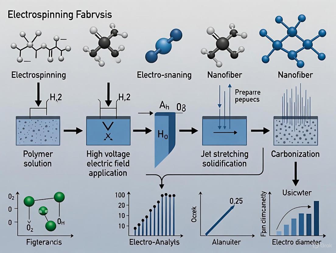
Diagram 1: Comprehensive electrospinning workflow from solution preparation to final fiber mat.
Experimental Protocol: Fabrication of Porous Carbon Nanofibers for Electrodes
Materials and Solution Preparation
Research Reagent Solutions and Essential Materials:
Table 3: Essential Materials for Carbon Nanofiber Fabrication
| Material | Function/Role | Specifications/Notes |
|---|---|---|
| Polyacrylonitrile (PAN) | Primary carbon precursor | MW ~150,000; provides carbon backbone after pyrolysis [5] |
| N,N-Dimethylformamide (DMF) | Solvent | Anhydrous, 99.8%; appropriate volatility and conductivity [5] |
| Pore-forming Agents | Create porous structure | Polysulfone (PSF), high amylose starch (HAS), or phenolic resin (PR) [5] |
| Distilled Water | Coagulation bath | For wet spinning variations; not always required |
| Inorganic Salts | Modify conductivity | e.g., NaCl, KH₂PO₄; enhance solution charge carrying capacity |
Step-by-Step Protocol
Phase 1: Polymer Solution Preparation
- Weighing: Accurately weigh PAN polymer and selected pore-forming agent (PSF, HAS, or PR) in 80:20 mass ratio [5]
- Dissolution: Add polymers to DMF solvent to achieve 9-15 wt% total polymer concentration [5]
- Mixing: Stir using magnetic stirrer at 50°C for 12-24 hours until homogeneous solution is obtained [5]
- Degassing: Allow solution to stand or centrifuge to remove air bubbles that could disrupt fiber continuity
Phase 2: Electrospinning Parameters Setup
- Syringe Loading: Transfer solution to standard syringe (5-20 mL capacity)
- Needle Selection: Attach metallic needle with 0.5-0.8 mm inner diameter [5]
- Flow Rate Adjustment: Set syringe pump to 0.5-1.0 mL/h based on solution viscosity [5]
- Voltage Application: Apply 15-25 kV high voltage between needle and collector [1]
- Distance Calibration: Set tip-to-collector distance to 10-20 cm [4]
- Environmental Control: Maintain temperature at 25±3°C and relative humidity at 40±5% [4]
Phase 3: Fiber Collection and Post-Processing
- Collection: Collect fibers on aluminum foil-covered rotating drum or static collector
- Stabilization: Heat fibers in air atmosphere at 200-300°C for 1-2 hours to crosslink structure [5]
- Carbonization: Pyrolyze stabilized fibers in inert atmosphere (N₂ or Ar) at 800-1200°C for 1 hour to convert to carbon nanofibers [5]
- Characterization: Analyze morphology (SEM), surface area (BET), and electrochemical properties
Critical Notes and Troubleshooting
- Bead Formation: Reduce flow rate or increase polymer concentration/viscosity [4] [3]
- Needle Clogging: Filter solution before spinning or increase solvent volatility
- Inconsistent Fiber Diameter: Ensure stable temperature and humidity conditions [4]
- Poor Carbon Yield: Optimize stabilization temperature and heating rate
Diagram 2: Interrelationship between different parameter classes in determining final fiber properties.
Characterization and Quality Control
For carbon nanofiber electrodes specifically, fabricated PCNFs using phenolic resin as pore-forming agent have demonstrated a specific surface area as high as ~994 m²/g and a total pore volume as high as ~0.75 cm³/g [5]. When used as active materials to fabricate electrodes, these PCNF-R electrodes show a high specific capacitance of ~350 F/g, good rate capability of ~72.6%, low internal resistance of ~0.55 Ω, and excellent cycling stability of ~100% after 10,000 charging and discharging cycles [5].
Essential characterization techniques include:
- Scanning Electron Microscopy (SEM): For fiber morphology and diameter distribution [5]
- X-ray Photoelectron Spectroscopy (XPS): For elemental composition analysis [5]
- BET Surface Area Analysis: For specific surface area and pore characteristics [5]
- Electrochemical Impedance Spectroscopy (EIS): For charge transfer resistance evaluation
- Cyclic Voltammetry: For specific capacitance measurement
Safety Considerations
Electrospinning involves several important safety aspects that must be addressed:
- High Voltage Safety: The electric field intensity for electrospinning should not exceed the safety limit of 20-30 kV/cm to prevent air ionization and serious risk of touching the setup parts [1]
- Solvent Handling: Use appropriate ventilation and personal protective equipment when handling organic solvents
- Nanoparticle Precautions: Implement engineering controls to prevent inhalation of nanofiber aerosols during collection
- Fire Safety: High-temperature furnaces for carbonization require proper installation and monitoring
This protocol provides a foundational methodology for the fabrication of electrospun carbon nanofiber electrodes, with specific parameters that can be optimized for particular application requirements in energy storage and other advanced applications.
The selection of precursor polymers is a critical foundational step in the electrospinning fabrication of high-performance carbon nanofiber (CNF) electrodes. These precursors determine the ultimate carbon yield, structural morphology, porosity, and surface chemistry of the resulting carbon fibers, which directly influence their electrochemical performance in applications such as supercapacitors, batteries, and sensors. Among the diverse polymer options, polyacrylonitrile (PAN), coal-derived precursors, and polyvinyl alcohol (PVA) have emerged as particularly significant systems, each offering distinct advantages and challenges. PAN is widely regarded as the industry benchmark due to its high carbon yield and exceptional fiber-forming capabilities, while PVA presents an environmentally friendly alternative with unique processing requirements. Coal-derived precursors offer a cost-effective and sustainable approach by valorizing an abundant natural resource.
The conversion of these polymeric precursors into functional carbon nanofibers follows a multi-stage pathway involving electrospinning, stabilization, and carbonization. During electrospinning, polymer solutions are drawn into continuous nanofibers under the influence of a high-voltage electric field, producing fibrous mats with high surface area-to-volume ratios. The stabilization process, typically conducted in air at temperatures of 200-300°C, renders the fibers infusible through cross-linking and cyclization reactions. Finally, carbonization at higher temperatures (600-1500°C) in an inert atmosphere converts the stabilized polymeric structure into a carbonaceous material with enhanced electrical conductivity and tailored porosity. Understanding the unique characteristics of each precursor polymer enables researchers to design carbon nanofiber electrodes with optimized properties for specific electrochemical applications.
Comparative Analysis of Precursor Polymers
Table 1: Key Characteristics of Precursor Polymers for Carbon Nanofibers
| Precursor Polymer | Carbon Yield (%) | Typical Carbonization Temperature (°C) | Key Advantages | Limitations & Challenges |
|---|---|---|---|---|
| Polyacrylonitrile (PAN) | 40-60% [6] [5] | 1000-1800 [6] | High carbon yield, excellent spinnability, good mechanical properties, well-established protocol | Requires expensive solvents (DMF), derived from crude oil, high carbonization temperatures [6] |
| Coal-Derived Precursors | Not specified | Adjusted via heat treatment [7] | Ultra-low cost, sustainable resource utilization, naturally abundant carbon content | Requires pretreatment, potential environmental concerns from processing, complex composition [7] |
| Polyvinyl Alcohol (PVA) | Up to 50% (with iodine treatment) [6] | 300 [8] | Water-soluble, non-toxic, low-cost, simple electrospinning | Low native carbon yield, requires chemical stabilization (e.g., iodine) [6] |
Table 2: Electrochemical Performance of Carbon Nanofibers from Different Precursors
| Precursor Polymer | Specific Surface Area (m²/g) | Specific Capacitance (F/g) | Key Applications Demonstrated |
|---|---|---|---|
| PAN | ~994 (with pore-formers) [5] | ~350 (with pore-formers) [5] | Supercapacitors [5], capacitive deionization [6] |
| Coal-Derived | Not specified | Not specified | Oil-water separation [7] |
| PVA | 1075-1131 (with iodine treatment) [6] | 127 (with iodine treatment) [6] | Supercapacitors [8], capacitive deionization [6] |
| PVA/Cr₂CTx MXene | 6.65 [8] | 338.8 [8] | Supercapacitors [8] |
Detailed Polymer Protocols and Applications
Polyacrylonitrile (PAN) Protocol
PAN stands as the most extensively studied and utilized precursor for producing carbon nanofibers due to its exceptional molecular orientation that facilitates high carbon yields and the formation of graphitic structures with good electrical conductivity. The PAN-based carbonization process is particularly advantageous because the nitrile groups (-C≡N) in the polymer backbone undergo cyclization during stabilization, forming ladder structures that are thermally stable and efficiently convert to carbon frameworks during high-temperature treatment.
Experimental Protocol for PAN-Based Carbon Nanofibers:
- Solution Preparation: Dissolve PAN powder in dimethylformamide (DMF) to create a 10-15% w/v solution. Stir continuously at 60-70°C for 6-12 hours to ensure complete dissolution and homogeneity [6] [5].
- Electrospinning Parameters:
- Voltage: 25-30 kV
- Flow rate: 0.4-0.5 mL/h
- Collector distance: 15-18 cm
- Collector type: Rotating drum or stationary plate
- Stabilization: Heat the electrospun PAN nanofibers in air at 220-280°C for 1-2 hours with a slow heating rate (1-5°C/min) to promote cyclization and oxidation without melting [5].
- Carbonization: Treat stabilized fibers in an inert atmosphere (N₂ or Ar) at 700-1500°C for 1 hour with a heating rate of 5°C/min to convert to carbon nanofibers [5].
Application Notes: For enhanced supercapacitor performance, incorporate template pore-forming agents (e.g., phenolic resin, polysulfone) at 20 wt% during solution preparation to create hierarchical porosity, increasing specific surface area to ~994 m²/g and specific capacitance to ~350 F/g [5]. The resulting electrodes exhibit excellent rate capability (72.6%) and cycling stability (100% retention after 10,000 cycles) [5].
Coal-Derived Precursors Protocol
Coal represents an abundant and low-cost carbon resource that can be directly incorporated into electrospinning formulations, offering a sustainable pathway for carbon nanofiber production. The inherent aromatic structures in coal contribute to enhanced graphitization potential, while its natural abundance provides economic advantages over synthetic polymers.
Experimental Protocol for Coal-Derived Carbon Nanofibers:
- Coal Preparation: Mill raw coal particles (e.g., from Heishan, China) and wash with water to obtain cleaned, uniform particles [7].
- Spinning Solution: Incorporate prepared coal particles into a PAN solution (acting as a co-polymer) using DMF as solvent [7].
- Electrospinning Parameters:
- Voltage: 25-30 kV
- Flow rate: 0.5 mL/h
- Collector distance: 15 cm
- Post-Treatment Options:
Application Notes: The resulting coal-derived fiber membranes demonstrate exceptional performance in oil-water separation applications, achieving up to 99.5% separation efficiency for water-in-oil emulsions with gravity-driven flux exceeding 600 L·m⁻²·h⁻¹ [7]. The membranes exhibit remarkable durability, maintaining super-hydrophobicity and self-cleaning performance during extended operation.
Polyvinyl Alcohol (PVA) Protocol
PVA offers distinct advantages as a water-soluble, non-toxic, and low-cost precursor, though its native carbon yield is limited due to high oxygen content. Recent advances in stabilization techniques, particularly using iodine vapor treatment, have significantly enhanced the carbon yield and properties of PVA-derived carbon nanofibers.
Experimental Protocol for PVA-Based Carbon Nanomats:
- Solution Preparation: Prepare a 12% w/w PVA solution (e.g., Elvanol T25, MW = 125,000 g/mol) in distilled water with heating at 90°C for 4 hours under continuous stirring [6].
- Electrospinning Parameters:
- Voltage: 25-30 kV
- Flow rate: 0.4 mL/h per needle
- Collector distance: 15 cm
- Relative humidity: 58-60%
- Iodine Treatment: Expose electrospun PVA mats to iodine vapors at 80°C for 6 hours to promote dehydrogenation and cross-linking [6].
- Heat Treatment: Apply controlled thermal treatment up to 900°C in inert atmosphere to convert to carbon nanomats [6].
Application Notes: PVA-derived carbon nanomats exhibit excellent properties for capacitive deionization electrodes, with specific surface areas of 1075-1131 m²/g featuring both micro and mesoporosity, and specific capacitance values of 77.8-127 F/g [6]. For enhanced supercapacitor performance, composite PVA/MXene fibers carbonized at 300°C for 1 hour demonstrate exceptional capacitive behavior (338.8 F·g⁻¹) and energy density (67.7 Wh·kg⁻¹) [8].
The Scientist's Toolkit: Essential Research Reagents
Table 3: Essential Research Reagents for Electrospinning Carbon Nanofibers
| Reagent/Material | Function/Purpose | Application Notes |
|---|---|---|
| Polyacrylonitrile (PAN) | Primary carbon precursor | High carbon yield (40-60%); requires DMF solvent [6] [5] |
| Polyvinyl Alcohol (PVA) | Water-soluble carbon precursor | Eco-friendly alternative; requires iodine treatment for improved carbon yield [6] |
| N,N-Dimethylformamide (DMF) | Solvent for PAN and coal mixtures | Hazardous; requires proper ventilation and handling [6] |
| Iodine | Chemical stabilizer for PVA | Enhances carbon yield to 50% via controlled dehydration [6] |
| Hexadecyltrimethoxysilane (HDTMS) | Hydrophobic coating agent | Imparts superhydrophobicity via vapor deposition [7] |
| Phenolic Resin (PR) | Pore-forming template | Creates mesopores; increases surface area to ~994 m²/g [5] |
| Cr₂CTx MXene | Conductive additive | Enhances capacitance (338.8 F/g) in PVA composites [8] |
The selection of precursor polymers for electrospun carbon nanofiber electrodes involves critical trade-offs between carbon yield, processing requirements, environmental considerations, and target applications. PAN remains the performance benchmark for electrochemical applications requiring high specific surface area and capacitance, despite its dependency on hazardous solvents. Coal-derived precursors offer an economically advantageous route particularly suited for separation applications, while PVA represents the most sustainable option with evolving stabilization protocols that continue to improve its electrochemical performance. Future research directions will likely focus on hybrid precursor systems that combine the advantages of multiple materials, advanced pore-forming techniques to optimize ion transport, and more environmentally benign processing methods to enable scalable production of high-performance carbon nanofiber electrodes.
Carbon Nanofiber (CNF) electrodes represent a significant advancement in materials science for electrochemical applications. These one-dimensional nanomaterials are characterized by a unique set of properties—high surface area, excellent electrical conductivity, and outstanding mechanical flexibility—that make them particularly suitable for demanding applications ranging from energy storage to biomedical devices. Within the context of electrospinning fabrication research, CNFs offer a versatile platform for creating tailored electrode architectures through controlled synthesis parameters. The electrospinning process enables precise manipulation of fiber morphology, diameter, and alignment, allowing researchers to engineer electrodes with optimized performance characteristics for specific applications. This application note details the quantitative advantages, fabrication protocols, and practical implementation of CNF electrodes within a research environment, providing a comprehensive resource for scientists and engineers working at the forefront of electrode development.
Quantitative Advantages of CNF Electrodes
The performance benefits of CNF electrodes are demonstrated through measurable metrics across multiple domains. The following tables summarize key quantitative data from recent research, highlighting the advantages of CNFs over conventional materials.
Table 1: Electrochemical Performance Metrics of CNF Electrodes for Energy Storage
| Material Type | Specific Capacitance (F/g) | Rate Capability | Cycling Stability | Specific Surface Area (m²/g) | Reference |
|---|---|---|---|---|---|
| Coal-derived Porous CNFs | 604 at 1 A/g | Not Specified | Stable over 10,000 cycles | Not Specified | [9] |
| Polymer-derived Porous CNFs (PCNF-R) | 350 at current density not specified | 72.6% | ~100% after 10,000 cycles | ~994 | [5] |
| Herringbone/Platelet CNFs | 26 at 0.2 A/g | Not Specified | Not Specified | 150-296 | [10] |
| Air-treated Tubular CNFs | 33 at 0.2 A/g | Not Specified | Not Specified | Increased after treatment | [10] |
Table 2: Comparative Material Properties of CNFs vs. Alternative Materials
| Property | CNFs | Traditional Activated Carbon | Carbon Nanotubes (CNTs) | Graphene |
|---|---|---|---|---|
| Specific Surface Area | Up to ~994 m²/g [5] | Often > 1800 m²/g [10] | Moderate (up to ~400 m²/g) [10] | High |
| Electrical Conductivity | High (less diffusion resistance) [9] | Moderate | Very High (10³-10⁴ S cm⁻¹) [10] | Very High |
| Mechanical Flexibility | Excellent (1D fibrous structure) [9] | Poor (brittle) | Good but can be rigid | Good |
| Biodegradability | Depends on precursor (e.g., cellulose-based) [11] | Not Biodegradable | Not Biodegradable | Not Biodegradable |
| Cost & Processing | Low-cost precursors (coal, biopolymers) [9] [5] | Low Cost | High Cost | High Cost |
The data reveals that the exposed edges of graphitic layers on the CNF surface significantly enhance capacitive behavior, sometimes playing a more critical role than the specific surface area alone [10]. Furthermore, the one-dimensional (1D) fibrous geometry of CNFs offers less diffusion resistance and better mechanical integrity compared to other carbon geometries [9].
Experimental Protocols for CNF Electrode Fabrication and Testing
Protocol 1: Electrospinning of Porous Carbon Nanofibers from Polymer Blends
This protocol details the fabrication of porous carbon nanofibers (PCNFs) using a template method with polyacrylonitrile (PAN) as a carbon source and various pore-forming agents, as validated by recent research [5].
Workflow Overview
Materials:
- Primary Polymer: Polyacrylonitrile (PAN, MW: 150,000)
- Pore-forming Agents: Polysulfone (PSF), High Amylose Starch (HAS), or Phenolic Resin (PR)
- Solvent: N,N-Dimethylformamide (DMF) or Dimethyl Sulfoxide (DMSO)
- Electrospinning Equipment: Syringe pump, high-voltage power supply, grounded collector
Procedure:
- Precursor Solution Preparation: Prepare a homogeneous polymer solution by dissolving PAN and your selected pore-forming agent (e.g., 20 wt% of PR) in DMF. Stir vigorously for 12-24 hours to ensure complete dissolution and mixing.
- Electrospinning: Load the solution into a syringe fitted with a metallic needle. Apply a high voltage (typically 10-20 kV) to the needle while maintaining a controlled flow rate (e.g., 0.5-1.0 mL/h). Collect the resulting nanofibers on a grounded collector placed at a fixed distance (e.g., 15-20 cm).
- Pre-oxidation (Stabilization): Subject the electrospun nanofiber mat to a pre-oxidation step in air. Use a programmed temperature ramp (e.g., 2-5°C/min) to a target temperature of 250-280°C, and hold for 1 hour. This step stabilizes the fibrous structure and prevents melting during carbonization.
- Carbonization: Transfer the stabilized fibers to a tube furnace and heat under an inert atmosphere (Nitrogen or Argon). Use a heating rate of 5°C/min to a final carbonization temperature between 800-1100°C. Maintain this temperature for 1-2 hours to convert the polymer into carbon.
- Post-processing: Allow the furnace to cool to room temperature under the inert gas flow. The resulting PCNF mat is now ready for characterization and electrode fabrication.
Protocol 2: Fabrication of a Symmetrical Supercapacitor Cell
This protocol describes the assembly of a two-electrode symmetrical supercapacitor cell for evaluating the electrochemical performance of the fabricated PCNFs.
Materials:
- Active Material: Prepared PCNF mat
- Binder: Polyvinylidene fluoride (PVDF)
- Solvent: N-Methyl-2-pyrrolidone (NMP)
- Current Collector: Metal foam (e.g., Nickel foam) or carbon-coated aluminum foil
- Electrolyte: 6 mol L⁻¹ Potassium Hydroxide (KOH) aqueous solution [10] or suitable organic electrolyte
- Separator: Glass fiber membrane or polypropylene separator
- Cell Hardware: CR2032 coin cell parts or a Swagelok-type cell
Procedure:
- Electrode Preparation:
- Mix the active material (PCNFs), conductive additive (e.g., carbon black), and binder (PVDF) in a mass ratio of 80:10:10. Use NMP as a solvent to form a homogeneous slurry.
- Coat the slurry onto the current collector. Alternatively, for freestanding CNF mats, cut the mat into precise discs and press them directly onto the current collector without a binder [9].
- Dry the electrodes in a vacuum oven at 100-120°C for at least 12 hours to remove residual solvent.
- Cell Assembly:
- In an argon-filled glovebox (for non-aqueous electrolytes) or in ambient conditions (for aqueous electrolytes), assemble the cell in the sequence: current collector, electrode, separator, electrode, current collector.
- Introduce the electrolyte to fully soak the separator and electrodes.
- Seal the cell using a hydraulic crimping machine (for coin cells) or by tightening the assembly (for Swagelok cells).
- Electrochemical Testing:
- Cyclic Voltammetry (CV): Perform CV tests at various scan rates (e.g., 5-100 mV/s) over a defined voltage window to observe the capacitive behavior (rectangular shape for ideal electric double-layer capacitors).
- Galvanostatic Charge-Discharge (GCD): Conduct GCD tests at different current densities (e.g., 0.2-5 A/g) to calculate specific capacitance, energy density, and power density. The specific capacitance ((Cs)) can be calculated from the discharge time using the formula: (Cs = 4I \Delta t / (m \Delta V)), where (I) is the current, (\Delta t) is the discharge time, (m) is the total mass of active material in both electrodes, and (\Delta V) is the voltage window.
- Electrochemical Impedance Spectroscopy (EIS): Perform EIS in a frequency range from 100 kHz to 10 mHz at an open-circuit potential with a small AC amplitude (e.g., 5 mV) to analyze the internal resistance and ion diffusion characteristics.
The Scientist's Toolkit: Essential Research Reagents and Materials
Table 3: Key Reagent Solutions for CNF Electrode Research
| Item | Function/Application | Key Considerations |
|---|---|---|
| Polyacrylonitrile (PAN) | A common polymer precursor for carbon nanofibers. | Molecular weight (e.g., 150,000) and purity affect spinnability and final carbon yield [9] [5]. |
| Polysulfone (PSF), Phenolic Resin (PR) | Polymer-based pore-forming agents. | The type of polymer used dictates the final pore structure and specific surface area of the CNFs [5]. |
| N,N-Dimethylformamide (DMF) | A polar aprotic solvent for dissolving polymer precursors. | Ensure anhydrous conditions for consistent solution viscosity and electrospinning performance. |
| Polyvinylidene Fluoride (PVDF) | Binder for electrode preparation. | Ensures adhesion of active materials to the current collector. Typically used at 5-10 wt% [10]. |
| 6 mol L⁻¹ KOH Solution | Aqueous electrolyte for supercapacitor testing. | Provides high ionic conductivity. The concentration is critical for consistent ion size and double-layer formation [10]. |
| Gold Current Collectors | Used in Swagelok-type test cells to avoid corrosion. | Prevents side reactions and data corruption during electrochemical testing, especially in alkaline electrolytes [10]. |
CNF Property Relationships and Performance Optimization
The performance of a CNF electrode is not governed by a single factor but by the complex interplay between its structural and textural parameters. Understanding these relationships is key to optimizing electrode design.
Property-Performance Relationships
As illustrated, exposed graphitic edges on the CNF surface facilitate more efficient ion charging compared to basal planes, significantly boosting capacitance [10]. While a high specific surface area provides more sites for ion adsorption, the pore size distribution is critical; pores in the range of 0.7 to 2 nm are ideal for accommodating hydrated ions in aqueous electrolytes, striking a balance between high capacitance and good rate capability [12]. Furthermore, incorporating heteroatoms like nitrogen and oxygen into the carbon matrix introduces fast faradaic reactions, which can dramatically increase pseudocapacitance, as demonstrated by coal-derived CNFs achieving 604 F g⁻¹ [9]. The one-dimensional fibrous morphology of CNFs inherently provides less diffusion resistance for ions and a continuous conductive pathway for electrons, underpinning high power density and mechanical robustness [9].
The carbonization process represents a critical thermal conversion step in the fabrication of high-performance carbon nanofiber (CNF) electrodes for electrochemical applications. This transformation involves the controlled pyrolysis of stabilized polymer precursors, typically polyacrylonitrile (PAN), into turbostratic carbon structures possessing enhanced electrical conductivity, thermal stability, and mechanical integrity. Within the context of electrospinning research, carbonization completes the transition from organic polymer nanofibers to inorganic carbon networks, enabling the development of advanced electrode materials for energy storage, biosensing, and catalytic applications. The structural and electrical properties of the final carbon nanofibers are profoundly influenced by carbonization parameters, particularly the final heat-treatment temperature and duration, which govern the development of graphitic domains and the elimination of non-carbon elements [13].
This protocol details the optimized procedures for carbonizing electrospun polymer nanofibers, with specific emphasis on achieving reproducible CNF electrodes with tailored properties for biomedical and energy applications. The methodologies described herein build upon established thermochemical principles while incorporating recent advances in process optimization based on microstructural evolution tracking [14]. When properly executed, this transformation yields carbon nanofiber networks with high surface area, tunable porosity, and excellent electrical conductivity—properties essential for high-performance electrodes in drug detection systems and diagnostic devices.
Theoretical Foundations: Structural Transformation Mechanisms
Chemical Evolution During Carbonization
The carbonization process induces fundamental chemical and structural changes in the stabilized polymer precursor. During this thermal treatment in an inert atmosphere, non-carbon elements (including hydrogen, oxygen, and nitrogen) are eliminated as volatile byproducts (e.g., H2O, CO2, CO, HCN, N2, CH4, and NH3), leading to an enrichment of carbon content and the formation of turbostratic carbon structures [13]. This elimination occurs through the breakdown of weaker chemical bonds and the reorganization of the cyclic ladder structure formed during stabilization into extended aromatic sheets.
The carbonization mechanism proceeds through several overlapping stages: (1) further cyclization and aromatization of the ladder polymer structure, (2) denitrogenation through elimination of nitrogen-containing groups, (3) condensation reactions leading to the growth of polyaromatic domains, and (4) crystallite orientation and growth. As the temperature increases, the size of the carbon crystallites expands exponentially, forming a network of graphene-like sheets with varying degrees of structural order [14]. The radial heterogeneity of the resulting carbon fibers, with more ordered structures typically forming at the periphery, significantly influences their final mechanical and electrical properties [14].
Structural Development and Electrical Properties
The development of electrical conductivity in carbonized fibers directly correlates with the growth and alignment of graphitic crystallites during carbonization. As the treatment temperature increases from 800°C to 1500°C, the interlayer spacing between graphene sheets decreases while crystallite size increases, enhancing electron delocalization and charge transport pathways [13]. This structural evolution transforms the electrically insulating polymer precursor into a conductive carbon network capable of functioning as an electrode material.
The transition in electrical properties occurs through a percolation mechanism where interconnected sp2-hybridized carbon domains form continuous conduction pathways. Above approximately 600°C, the material exhibits semiconductor behavior, with conductivity increasing exponentially with temperature. At higher carbonization temperatures (1000-1400°C), the fibers develop metallic conduction characteristics as the crystallite size increases and structural defects are annealed out [13]. This relationship between thermal treatment and electronic properties enables precise tuning of electrode performance for specific applications.
Table 1: Effect of Carbonization Temperature on Structural and Electrical Properties of PAN-Based Carbon Nanofibers
| Carbonization Temperature (°C) | Crystallite Size (nm) | Interlayer Spacing (nm) | Electrical Conductivity (S/cm) | Carbon Content (%) |
|---|---|---|---|---|
| 800 | 1.2-1.5 | 0.360-0.375 | 1-10 | 85-90 |
| 1000 | 1.5-2.0 | 0.350-0.360 | 10-50 | 90-93 |
| 1200 | 2.0-2.8 | 0.345-0.350 | 50-200 | 93-95 |
| 1400 | 2.8-3.5 | 0.340-0.345 | 200-1000 | 95-98 |
Experimental Protocols
Precursor Preparation and Electrospinning
Materials Requirements:
- Polymer Precursor: Polyacrylonitrile (PAN, Mw = 150,000 g/mol) is recommended as the primary precursor due to its high carbon yield (~50%) and excellent mechanical properties in the resulting fibers [13].
- Solvent: N,N-Dimethylformamide (DMF, ≥99% purity) for preparing electrospinning solutions.
- Alternative Polymers: Polyvinyl alcohol (PVA) or polyvinylpyrrolidone (PVP) may be used for specific applications requiring different surface functionalities [8] [15].
Electrospinning Solution Preparation:
- Prepare a 8-12% (w/v) PAN solution in DMF by dissolving 0.5 g of PAN pellets in 10 mL of DMF [13].
- Stir continuously using a magnetic stirrer for 12-24 hours at room temperature (20-25°C) until a homogeneous, viscous solution is obtained without visible particles or gelation.
- For functionalized CNFs, additives such as metal nanoparticles (e.g., Cr2CTx MXene) or pore-forming agents (e.g., polyvinylpyrrolidone) may be incorporated at this stage with concentration typically between 0.5-5% of polymer weight [8].
Electrospinning Parameters:
- Applied Voltage: 15-25 kV (optimized at 24 kV for PAN/DMF systems)
- Needle-to-Collector Distance: 15-20 cm (optimized at 18 cm)
- Solution Flow Rate: 0.3-1.0 mL/h (optimized at 0.5 mL/h)
- Collector Type: Rotating drum collector for aligned fibers; stationary plate for random orientation
- Environmental Conditions: Maintain at 20-25°C and 40-50% relative humidity [13] [3]
Stabilization Process
Stabilization is an essential prerequisite step that renders the electrospun polymer fibers infusible and prepares their molecular structure for carbonization. This process involves heating the PAN-based fibers in an oxidative atmosphere to induce cyclization and cross-linking reactions.
Standard Stabilization Protocol:
- Transfer the electrospun PAN nanofiber mat to a tube furnace or muffle furnace capable of precise temperature programming.
- Implement the following temperature ramp under air atmosphere:
- Heat from room temperature to 200°C at 1-3°C/min
- Hold at 200°C for 30 minutes
- Increase temperature to 250°C at 1°C/min
- Hold at 250°C for 60 minutes
- Finally, increase to 280-300°C at 1°C/min and maintain for 60 minutes [13]
- Ensure adequate air circulation throughout the process to facilitate uniform oxidation.
- Allow fibers to cool slowly to room temperature before proceeding to carbonization.
During stabilization, the linear PAN chains undergo cyclization, dehydrogenation, aromatization, and oxidation, converting the triple bond (C≡N) to a double bond (C=N) and forming a thermally stable ladder polymer structure [13]. Proper stabilization prevents melting or fusion of fibers during subsequent high-temperature treatment and is critical for achieving high mechanical strength in the final carbon fibers.
Carbonization Process
The carbonization process transforms the stabilized polymer fibers into carbon nanofibers through controlled pyrolysis in an inert atmosphere. The following protocol has been optimized based on microstructural evolution studies [14].
Equipment Setup:
- High-temperature tube furnace with programmable temperature controller
- Inert gas supply (high-purity nitrogen or argon, ≥99.99%)
- Gas flow regulators and flowmeters
- Quartz or alumina boat holders for fiber mats
- Cooling system with water jacket or forced air
Standard Carbonization Procedure:
- Place the stabilized fiber mat in a quartz boat, ensuring minimal folding or compression to maintain fiber morphology.
- Insert the boat into the center of the tube furnace, ensuring uniform thermal environment.
- Seal the furnace and purge with inert gas (N2 or Ar) at a flow rate of 100-200 mL/min for 30-60 minutes to eliminate oxygen.
- Implement the following temperature program under continuous inert gas flow:
- Ramp from room temperature to 500°C at 5°C/min
- Hold at 500°C for 30 minutes to allow gradual devolatilization
- Increase to the target carbonization temperature (800-1400°C) at 3-5°C/min
- Maintain at the target temperature for a specific duration (typically 30-120 minutes)
- Cool to room temperature at 2-5°C/min under continued inert gas flow [14] [13]
Optimized Carbonization Parameters: Recent studies tracking microstructural evolution have identified an optimal carbonization condition of 1300°C for 2 minutes, which produces carbon fibers with a tensile strength of 3.97 GPa and a tensile modulus of 234 GPa [14]. This shorter duration at higher temperature minimizes radial heterogeneity while achieving sufficient carbon crystallite growth.
Table 2: Carbonization Parameters and Resulting Fiber Properties
| Application Target | Temperature Range (°C) | Time (min) | Atmosphere | Heating Rate (°C/min) | Key Properties |
|---|---|---|---|---|---|
| Standard CNFs | 1000-1200 | 60-120 | N2 | 5 | Conductivity: 50-200 S/cm, Tensile Strength: 2-3 GPa |
| High-Performance Electrodes | 1200-1400 | 30-60 | N2 or Ar | 3-5 | Conductivity: 200-1000 S/cm, Tensile Strength: 3-4 GPa |
| Optimized Structural Properties | 1300 | 2-5 | N2 | 10 | Tensile Strength: 3.97 GPa, Modulus: 234 GPa [14] |
| Functionalized CNFs | 800-1000 | 60 | N2 | 3 | High surface functionality, Moderate conductivity |
Characterization and Quality Assessment
Structural and Morphological Analysis
Comprehensive characterization of carbonized nanofibers is essential for quality control and property verification. The following techniques provide critical insights into structural development:
Scanning Electron Microscopy (SEM):
- Assess fiber morphology, diameter distribution, and surface topography
- Identify defects, fusion points, or structural collapse
- Confirm maintenance of fibrous structure after carbonization
- Typical PAN-based CNFs show diameters of 196-331 nm after carbonization at 1000-1400°C [13]
Transmission Electron Microscopy (TEM):
- Resolve internal microstructure and crystallite organization
- Identify graphitic domain formation and alignment
- Detect heteroatoms or incorporated nanoparticles in functionalized CNFs
X-Ray Diffraction (XRD):
- Determine degree of structural order and crystallite size using Scherrer equation
- Calculate interlayer spacing (d002) from Bragg position
- Monitor transition from amorphous to turbostratic structure
- Typical d-spacing values decrease from ~0.375 nm to ~0.342 nm with increasing carbonization temperature [13]
Raman Spectroscopy:
- Quantify defect density through D/G band intensity ratio (ID/IG)
- Assess graphitization level and structural ordering
- Typical ID/IG values range from 1.2-0.8 for carbonization temperatures of 800-1400°C
Electrical and Electrochemical Properties
Electrical Conductivity Measurement:
- Use four-point probe method or Hall effect measurements
- Document exponential increase in conductivity with carbonization temperature
- Expected values range from 10 S/cm (800°C) to >1000 S/cm (1400°C) [13]
Electrochemical Characterization for Electrode Applications:
- Perform cyclic voltammetry in 3M KOH electrolyte for supercapacitor applications
- Conduct galvanostatic charge-discharge testing to determine specific capacitance
- Typical specific capacitance values for CNF electrodes range from 150-350 F/g depending on surface functionality and porosity [8]
- Electrochemical impedance spectroscopy to assess charge transfer resistance
Table 3: Troubleshooting Guide for Carbonization Process
| Problem | Potential Causes | Solutions |
|---|---|---|
| Brittle fibers | Excessive heating rate, Incomplete stabilization, Over-carbonization | Optimize stabilization, Reduce heating rate to 3°C/min, Lower final temperature |
| Fused fibers | Inadequate stabilization, Localized overheating, Excessive temperature | Verify complete stabilization, Ensure uniform temperature in furnace, Reduce final temperature |
| Low conductivity | Insufficient carbonization temperature, Short dwell time, Oxygen contamination | Increase final temperature (≥1000°C), Extend dwell time (≥60 min), Verify inert gas purity and flow |
| Radial heterogeneity | Rapid heating, Temperature gradients in furnace | Implement slower heating rates (3°C/min), Use furnace with uniform hot zone, Optimize based on microstructure tracking [14] |
| Structural collapse | Excessive gas evolution, Rapid devolatilization | Implement staged heating with holds at 500°C and 800°C, Reduce heating rate through decomposition range |
Research Reagent Solutions
Table 4: Essential Materials for Carbon Nanofiber Fabrication
| Reagent/Material | Specifications | Function | Application Notes |
|---|---|---|---|
| Polyacrylonitrile (PAN) | Mw = 150,000 g/mol, >99% purity | Primary carbon precursor | Provides high carbon yield (~50%), excellent spinnability, and good mechanical properties in final fibers [13] |
| N,N-Dimethylformamide (DMF) | Anhydrous, ≥99.8%, H2O <0.005% | Solvent for electrospinning | Provides appropriate viscosity and conductivity for electrospinning, readily dissolves PAN |
| Nitrogen Gas | High purity, ≥99.99%, O2 <10 ppm | Inert atmosphere for carbonization | Prevents oxidative degradation during high-temperature treatment |
| Polyvinyl Alcohol (PVA) | Mw = 85,000-124,000, 87-89% hydrolyzed | Alternative polymer precursor | Sustainable precursor producing CNFs with different surface chemistry [8] |
| Cr2CTx MXene | Synthesized from Cr2AlC MAX phase, etched with HF | Conductive additive | Enhances electrical conductivity and introduces pseudocapacitive behavior (338.8 F/g reported) [8] |
| Melamine | Reagent grade, ≥99% | Nitrogen-doping agent | Introduces nitrogen functional groups for enhanced electrochemical activity and metal adsorption [15] |
Applications in Electrochemical Systems
Carbon nanofibers produced through electrospinning and carbonization demonstrate exceptional versatility in electrochemical applications, particularly as advanced electrode materials.
Energy Storage Systems
Carbonized CNFs serve as excellent electrode materials for supercapacitors and lithium-based batteries due to their high electrical conductivity, tunable porosity, and mechanical resilience. Specific applications include:
Supercapacitor Electrodes: CNFs with specific surface areas of 6.65 m2/g (for Cr2CTx/CNF composites) have demonstrated capacitances of 338.8 F/g with energy density of 67.7 Wh/kg and power density of 1998 W/kg [8]. The continuous conductive network facilitates rapid electron transport, while the porous structure enables efficient ion diffusion.
Lithium-Ion Battery Components: CNFs function as conductive additives in cathodes (e.g., LiCoO2, LiFePO4) and as standalone anodes, with core-shell LiCoO2-MgO NFs showing 90.0% capacity retention after 40 cycles compared to 52.0% for bare LiCoO2 [16]. The fibrous architecture accommodates volume expansion during charge-discharge cycles, enhancing cycling stability.
Biomedical Sensing and Environmental Applications
Functionalized carbon nanofibers find applications in biomedical sensing and environmental remediation:
Heavy Metal Adsorption: Amine-functionalized CNFs (melam-ECNFs and PmPDA-ECNFs) exhibit excellent adsorption capacity for lead ions (Pb2+) from aqueous solutions, with the adsorption process being endothermic and spontaneous for most functionalized variants [15]. The high surface area and introduced functional groups facilitate efficient metal ion capture.
Biosensing Platforms: CNF-based electrodes serve as transduction elements in electrochemical biosensors for healthcare monitoring, including wearable sensors, pressure sensors, and glucose sensors [3]. Their high conductivity and biocompatibility make them ideal for implantable and wearable diagnostic devices.
Workflow and Process Optimization
The following diagram illustrates the complete carbon nanofiber fabrication workflow from precursor preparation to final application, highlighting critical control points and decision nodes:
Process Optimization Strategy: Recent advances in carbonization optimization involve tracking microstructural evolution in real-time to establish correlations between processing parameters and final properties. Studies demonstrate that structural changes in the radial direction critically affect mechanical properties, with optimal carbonization conditions identified as 1300°C for 2 minutes based on comprehensive analysis of carbon crystallite development and void dimensions [14]. This microstructure-informed approach enables targeted optimization rather than empirical parameter adjustment.
The carbonization protocols detailed herein provide a foundation for fabricating high-performance carbon nanofiber electrodes with tailored properties for specific applications. By controlling critical parameters—particularly final temperature, dwell time, and heating rate—researchers can precisely engineer the structural, electrical, and electrochemical characteristics of CNF-based electrodes to meet the demanding requirements of modern energy storage and biomedical sensing platforms.
Advanced Fabrication Methods and Emerging Applications in Biomedicine
Electrospinning is a versatile and efficient technique for the fabrication of micro- and nanoscale fibers, which has garnered significant interest in the field of materials science, particularly for the fabrication of carbon nanofiber electrodes for energy storage [17]. This article provides a detailed overview of three principal electrospinning techniques—Far-Field, Near-Field, and Melt Electrospinning—framed within the context of developing high-performance supercapacitor components. These techniques enable the production of fibers with high surface area-to-volume ratios, tunable porosity, and excellent electrochemical properties, making them ideal for applications in energy storage, medical devices, filtration, and advanced textiles [18] [17]. The following sections will delineate the core principles, experimental protocols, and specific applications of each technique, supplemented with structured quantitative comparisons and detailed methodologies to serve as a comprehensive guide for researchers and scientists engaged in the development of next-generation carbon-based electrodes.
Far-Field Electrospinning (Conventional Electrospinning)
Core Principles and Setup
Far-Field Electrospinning (FF-ES) is the most widespread technique for producing nanofibers. It employs a high-voltage electrostatic field (typically several thousand to tens of thousands of volts) to draw a charged polymer solution from a nozzle tip onto a collector placed at a distance ranging from 10 to 20 centimeters [17] [19]. The process begins with the formation of a Taylor cone at the nozzle. When the electrostatic force overcomes the solution's surface tension, a continuous jet is ejected. This jet undergoes a whipping instability, leading to extensive stretching and thinning before the solvent evaporates, resulting in solid nanofibers with diameters ranging from tens of nanometers to several micrometers that are collected as non-woven mats [17] [18]. A basic FF-ES setup comprises four main components: a high-voltage power supply, a solution storage unit (e.g., a syringe), an ejection device (e.g., a metal needle), and a collecting device [17].
Experimental Protocol for Carbon Nanofiber Electrodes
Objective: To fabricate porous carbon nanofibers for supercapacitor electrodes using a polymer blend and far-field electrospinning [5].
Materials and Reagent Solutions:
- Polymer Carbon Source: Polyacrylonitrile (PAN, Mw = 150,000).
- Pore-Forming Agent: Polystyrene (PS, Mw = 35,000) or Phenolic Resin (PR).
- Solvent: N,N-Dimethylformamide (DMF).
- Equipment: Syringe pump, high-voltage power supply, metal collector.
Procedure:
- Solution Preparation: Prepare a 10 wt% PAN solution in DMF and a 10 wt% PS solution in DMF. Stir each solution separately for 12 hours at 60°C. Mix the PAN and PS solutions in a 1:1 weight ratio and stir for an additional 3 hours to achieve a homogeneous polymer blend [20].
- Electrospinning Parameters:
- Post-Processing: Collect the electrospun non-woven nanofiber mat.
- Stabilization and Carbonization: Subject the nanofiber mat to thermal treatment. This typically involves stabilization in air at ~280°C, followed by carbonization in an inert atmosphere (e.g., Argon) at high temperature (e.g., 800°C) for 1 hour [20]. During carbonization, the PAN converts to carbon, while the PS decomposes, creating a porous structure.
Key Processing Considerations:
- Solution Viscosity: Optimize polymer concentration to ensure spinnability and avoid bead formation. A viscosity range of 300-600 mPa·s is often effective [9] [21].
- Solvent Volatility: The solvent must have adequate volatility to allow for jet solidification before reaching the collector.
- Environmental Control: Maintain temperature and humidity (e.g., 20-40°C, 30-60% humidity) to ensure consistent fiber morphology [21] [17].
Application in Carbon Nanofiber Electrodes
FF-ES is extensively used to create the porous, conductive carbon nanofiber scaffolds essential for supercapacitors. By using alternative precursors like coal-derived polyurethane (CPU), researchers have fabricated electrodes that eliminate the need for expensive commercial polymers like PAN. These electrodes demonstrate superior electrochemical performance, with a specific capacitance of 604 F g⁻¹ at 1 A g⁻¹ and excellent stability over 10,000 cycles [9]. The far-field technique is prized for its simplicity and ability to produce high-surface-area mats ideal for ion adsorption/desorption [5].
Near-Field Electrospinning (NF-ES)
Core Principles and Setup
Near-Field Electrospinning is an advanced technique designed for the direct and precise deposition of micro- and nanofibers. Its primary distinction from FF-ES is the drastically reduced tip-to-collector distance, typically 0.5 to 2 millimeters, and the use of a lower voltage (200 V to 600 V) [19]. This small distance minimizes the whipping instability characteristic of FF-ES, allowing for controlled jet deposition and the creation of patterned, aligned structures. In some NF-ES setups, a mechanical drawing force from a translating collector further aids in fiber stretching and placement precision [19]. The process sometimes requires an initial higher voltage to initiate the jet, which is then reduced to a stable working voltage for consistent deposition [19].
Experimental Protocol for Direct Writing of Fibers
Objective: To achieve direct writing and patterning of polymer fibers using near-field electrospinning.
Materials and Reagent Solutions:
- Polymer: Polyethylene oxide (PEO) or Polydioxanone.
- Solvent: Deionized water or appropriate organic solvent.
- Equipment: Precision syringe pump, low-voltage high-voltage power supply, programmable translational collector.
Procedure:
- Solution Preparation: Prepare a spinnable polymer solution (e.g., 5-10 wt% PEO in water) with optimized viscosity and conductivity.
- NF-ES Parameters:
- Jet Initiation and Patterning: For low-voltage setups, a tungsten or glass microprobe tip may be used to mechanically draw the solution and initiate the jet [19]. Alternatively, a short burst of higher voltage can be used for initiation before switching to the lower working voltage [19]. The programmable collector stage is then moved along a pre-defined path to "write" with the fiber.
Key Processing Considerations:
- Fiber Diameter Control: Fiber diameter is highly sensitive to collector speed. Higher translational speeds result in mechanical drawing and smaller fiber diameters (e.g., from 10 µm at 10 mm/s to 3.7 µm at 100 mm/s) [19].
- Jet Stability: Low voltage and a stable, short working distance are critical for maintaining a stable jet and achieving precise deposition.
- Precision Guidance: The electrospinning jet can be guided onto specific, pre-patterned collector features (e.g., carbon pillars) to achieve even greater placement accuracy [19].
Application in Carbon Nanofiber Electrodes
While NF-ES is more common in applications requiring precise fiber placement like biosensors and tissue engineering [17], its potential in carbon nanofiber research lies in creating structured electrode architectures. For instance, directly writing interdigitated micro-supercapacitor patterns or creating well-defined porous networks could enhance ion transport pathways and electrochemical performance. The ability to stack fibers vertically also opens avenues for building 3D electrode structures [19].
Melt Electrospinning (M-ES)
Core Principles and Setup
Melt Electrospinning substitutes a polymer melt for a polymer solution, eliminating the need for solvents. The core principle remains the use of an electric field to draw a polymer jet from a melt, which then solidifies primarily through cooling rather than solvent evaporation [22]. This technique addresses the significant challenges associated with solvent use in traditional electrospinning, such as toxicity, environmental impact, and residual solvent in the final fibers [17] [22]. However, M-ES faces its own set of challenges, including the high viscosity of polymer melts and their low ionic conductivity, which often results in larger fiber diameters, typically in the micrometer range (> 2 µm) [22] [23]. Scaling up the process also presents engineering challenges [22].
Experimental Protocol for Solvent-Free Fibers
Objective: To produce sub-microfibers and nanofibers from polymer melts without using solvents.
Materials and Reagent Solutions:
- Polymer: Polylactic acid (PLA) or Polycaprolactone (PCL).
- Additive: Sodium stearate (6% w/w) to enhance conductivity and reduce melt viscosity [22].
- Equipment: Melt electrospinning device with temperature-controlled syringe, heating jacket, high-voltage power supply.
Procedure:
- Material Preparation: Dry the polymer pellets thoroughly to remove moisture. Mix with conductivity-enhancing additives if necessary.
- Melt-Electrospinning Parameters:
- Nozzle Diameter: Varies; multi-nozzle spinnarets with 600 nozzles have been used for scale-up [22].
- Applied Voltage: 10-30 kV.
- Temperature: Set the heating system to a temperature 20-50°C above the polymer's melting point (e.g., ~175°C for PLA, ~60°C for PCL) [18] [22].
- Flow Rate: Precisely controlled via a melt pump or piston.
- Tip-to-Collector Distance: 1-10 cm.
- Collection: The solidified fibers are collected on a grounded collector. An uneven collector surface can help in spreading the fiber web [22].
Key Processing Considerations:
- Thermal Degradation: Avoid excessive heating temperatures and prolonged residence times to prevent polymer degradation.
- Jet Stability: The high viscosity of the melt can lead to unstable jet formation. Using an open flat-plate configuration instead of a needle, and adding commercial conductivity enhancers, can help form more stable jets and push towards nanofiber formation [23].
- Throughput: Single-needle setups have low yield. Scale-up requires multi-nozzle systems or needleless approaches like rotary cone electrospinning [18] [22].
Application in Carbon Nanofiber Electrodes
Melt electrospinning offers a "green" pathway to carbon nanofiber precursors. Fibers spun from polymers like PLA or PAN can undergo thermal stabilization and carbonization to become conductive carbon fibers. Since no solvent is used, there is no risk of pore collapse or contamination from solvent residues, which can be beneficial for creating controlled porous structures. The primary challenge remains achieving diameters small enough to compete with solution-electrospun carbon nanofibers, though ongoing research in additives and process optimization is addressing this limitation [22].
Comparative Analysis of Electrospinning Techniques
The following table summarizes the key characteristics, advantages, and limitations of the three electrospinning techniques discussed.
Table 1: Comparative summary of far-field, near-field, and melt electrospinning techniques.
| Feature | Far-Field Electrospinning | Near-Field Electrospinning | Melt Electrospinning |
|---|---|---|---|
| Typical Distance | 10-20 cm [17] | 0.5-2 mm [19] | 1-10 cm [22] |
| Typical Voltage | 10-28 kV [21] | 200-600 V [19] | 10-30 kV |
| Typical Fiber Diameter | 50 nm - 5 µm | 20 nm - 20 µm [19] | > 2 µm (can reach 80 nm with optimization) [22] |
| Primary Fiber Collection | Non-woven mat | Direct-write patterns | Non-woven mat |
| Key Advantages | Simple setup; Versatile material use; High surface area mats | Precise fiber placement; Controlled alignment and patterning | Solvent-free; Environmentally friendly; No solvent toxicity |
| Key Limitations | Use of toxic solvents; Low production rate; Random fiber orientation | Low production rate; Complex setup; Limited to viscous solutions | High viscosity; Low conductivity; Larger fiber diameters; Thermal degradation risk |
Essential Research Reagent Solutions
The table below details key materials and their functions in the electrospinning fabrication of carbon nanofiber electrodes.
Table 2: Key research reagents and materials for electrospinning carbon nanofiber electrodes.
| Material Category | Example | Function in Research |
|---|---|---|
| Carbon Precursor | Polyacrylonitrile (PAN) [5] [20] | The most common polymer precursor; provides high carbon yield after pyrolysis. |
| Alternative Precursor | Coal-derived Polyurethane (CPU) [9] | Low-cost alternative to PAN; creates porous, nitrogen/oxygen-rich surfaces for enhanced faradaic reactions. |
| Pore-Forming Agent | Polystyrene (PS), Phenolic Resin (PR) [5] [20] | Creates porosity within the carbon fiber during carbonization via thermal decomposition. |
| Solvent | N,N-Dimethylformamide (DMF) [9] [5] | Dissolves polymer precursors to create a spinnable solution with appropriate viscosity and conductivity. |
| Conductivity Additive | Sodium Stearate [22] | Used in melt electrospinning to enhance the electrical conductivity of the polymer melt. |
| Plasma Gas | Oxygen (O₂) [20] | Used in post-electrospinning plasma treatment to activate carbon nanofiber surface, increasing surface area and introducing functional groups. |
Workflow and Decision Pathway
The following diagram illustrates a generalized experimental workflow for fabricating carbon nanofiber electrodes, integrating the three electrospinning techniques and subsequent processing steps.
Electrode Fabrication Workflow
Far-Field, Near-Field, and Melt Electrospinning each offer distinct advantages and confront unique challenges in the fabrication of carbon nanofiber electrodes. Far-Field ES remains the cornerstone for producing high-surface-area mats efficiently. Near-Field ES provides unparalleled control for creating sophisticated micro-architectures that may enhance electrochemical performance. Melt ES presents a sustainable, solvent-free route, though achieving nanoscale diameters requires further innovation. The choice of technique is not mutually exclusive; rather, it is dictated by the specific performance requirements of the target application, such as energy density, power density, and cost. Future advancements will likely focus on hybrid approaches, scaling up production through multi-nozzle and needleless systems, and developing novel precursor materials to push the boundaries of carbon nanofiber electrode capabilities.
Electrospun carbon nanofiber (CNF) electrodes represent a frontier in advanced material engineering, combining high conductivity, mechanical flexibility, and exceptional surface area. The integration of MXenes, metals, and metal oxides into CNF matrices has unlocked new possibilities for creating next-generation energy storage and environmental applications. These composites leverage the unique properties of each component: MXenes provide outstanding electrical conductivity and surface functionality, metals contribute catalytic activity and magnetic properties, and metal oxides offer rich redox chemistry for enhanced energy storage. This protocol details the synthesis, optimization, and application of these advanced composite materials, providing researchers with a comprehensive framework for developing high-performance electrode systems. The methodologies outlined herein are particularly relevant for applications demanding high conductivity, specific capacitance, and structural stability under mechanical stress.
Composite Performance Comparison
The table below summarizes the electrochemical performance of various CNF-based composites reported in recent literature, providing a benchmark for researchers developing these materials.
Table 1: Performance Metrics of Advanced CNF Composites
| Composite Material | Specific Capacitance | Energy Density | Power Density | Cycling Stability | Key Applications | Citation |
|---|---|---|---|---|---|---|
| High Entropy Metal/Metal Oxide/CNF (Fe,Co,Ni,Cu,Mn) | 215 F g⁻¹ at 1 mA cm⁻² | 26.0 Wh kg⁻¹ (symmetric), 41 Wh kg⁻¹ (asymmetric) | 400-10,000 W kg⁻¹ | 90% retention after 10,000 cycles | Supercapacitors, Energy Storage | [24] |
| Cr₂CTx/CNF | 338.8 F g⁻¹ | 67.7 Wh kg⁻¹ | 1998 W kg⁻¹ | Not specified | Supercapacitors | [8] |
| MXene-Cellulose NF | 94.21 F cm⁻³ (volumetric) | 3.27 mWh cm⁻³ | 0.25 W cm⁻³ | 97.87% retention after 10,000 bending cycles | Flexible All-Solid-State Supercapacitors | [25] |
| Fe₀.₆₄Ni₀.₃₆/MXene/CNF | Not applicable (EM wave absorber) | Not applicable | Not applicable | Not applicable | Electromagnetic Wave Absorption | [26] |
| NTO-MXene/CNF | Not applicable (CDI application) | Not applicable | Not applicable | Good cycling stability | Capacitive Deionization, Water Desalination | [27] |
Experimental Protocols
High Entropy Metal/Metal Oxide-CNF Composites
Principle: This approach utilizes the entropic stabilization of multiple metal components (typically five or more) in equivalent or near-equivalent ratios to create thermally and electrochemically stable composite structures. The high-entropy configuration maximizes configurational entropy according to the Gibbs Helmholtz equation, lowering Gibbs free energy and enhancing electrochemical stability through synergistic effects between metal components [24].
Materials:
- Polymer precursor: Polyacrylonitrile (PAN, Mw: 150,000)
- Metal precursors: Manganese(II) acetate tetrahydrate, Iron(II) acetate, Cobalt(II) acetate tetrahydrate, Nickel(II) acetate tetrahydrate, Copper(II) acetate
- Solvent: N,N-Dimethylformamide (DMF, 99.8%)
- Electrolyte: 6 M KOH for electrochemical testing
Procedure:
- Precursor Solution Preparation: Dissolve equimolar concentrations (0.5 mmol each) of Mn, Fe, Co, Ni, and Cu acetates in DMF with continuous stirring.
- Polymer Integration: Add PAN (8-10 wt%) to the metal precursor solution and stir vigorously until a homogeneous spinning solution is obtained.
- Electrospinning Parameters:
- Voltage: 15-25 kV
- Flow rate: 0.5-1.0 mL h⁻¹
- Collector distance: 15-20 cm
- Ambient temperature and humidity control (25°C, 40% RH)
- Oxidation Stabilization: Treat the as-spun fibers in air at 220-280°C for 1-3 hours to induce cross-linking and prevent melting during carbonization.
- Carbonization: Heat treated fibers at 700-900°C under inert atmosphere (N₂ or Ar) for 1-2 hours to convert polymer to carbon matrix and form metal/metal oxide crystalline structures.
- Morphological Control: Vary metal acetate precursor concentration and oxidation stabilization time to control porosity and nanoparticle distribution [24].
Key Characterization:
- FE-SEM for fiber morphology (300-450 nm diameter typical)
- XRD to confirm crystalline metallic alloy nanoparticle formation
- BET surface area analysis
- Electrochemical impedance spectroscopy
MXene-CNF Composite Fabrication
Principle: MXenes (2D transition metal carbides/nitrides) enhance CNF conductivity and introduce pseudocapacitive behavior. Their surface functional groups (-OH, -F, -O) facilitate strong interfacial interactions with the carbon matrix, while preventing restacking of MXene layers through intercalation within the fiber structure [27] [8].
Materials:
- MXene precursor: Ti₃AlC₂ MAX phase (for Ti₃C₂Tₓ MXene) or Cr₂AlC (for Cr₂CTₓ MXene)
- Etching solution: Lithium fluoride (LiF) in hydrochloric acid (HCl)
- Polymer matrix: Polyacrylonitrile (PAN) or Polyvinyl alcohol (PVA)
- Solvent: Deionized water or DMF
MXene Synthesis Protocol:
- Selective Etching: Mix 1.6 g LiF with 20 mL of 9 M HCl with vigorous stirring for 30 minutes.
- MAX Phase Addition: Gradually add 1 g Ti₃AlC₂ or Cr₂AlC precursor over 10 minutes to prevent excessive exothermic reaction.
- Etching Reaction: Stir reaction mixture in 35°C water bath for 24-72 hours.
- Washing: Centrifuge resulting mixture at 5000 rpm and wash with deionized water repeatedly until supernatant reaches neutral pH (≈6-7).
- Delamination: Sonicate precipitate for 15-30 minutes and centrifuge at 3000-4000 rpm for 1 hour to collect MXene supernatant [25] [8].
Composite Electrospinning Protocol:
- Spinning Solution: Prepare homogeneous dispersion of 0.5-2.0 wt% MXene in polymer solution (8-10 wt% PAN in DMF or 10 wt% PVA in water).
- Electrospinning Parameters:
- Voltage: 20-25 kV
- Flow rate: 0.3-0.8 mL h⁻¹
- Needle-to-collector distance: 15-20 cm
- Carbonization: Pyrolyze electrospun mats at 300-800°C in inert atmosphere for 1-2 hours [8].
Critical Parameters:
- MXene dispersion quality (sonication time and power)
- MXene to polymer ratio (typically 1:10 to 1:20)
- Carbonization temperature (affects conductivity and stability)
Flexible MXene-Cellulose Nanofiber Composites
Principle: Cellulose nanofibers (CNFs) provide sustainable, mechanically robust scaffolding that prevents MXene stacking, enhances ionic transport, and improves flexibility while maintaining electrochemical performance. The hydrophilic nature of CNFs improves electrolyte accessibility [25].
Materials:
- Cellulose nanofibers (aqueous dispersion)
- MXene suspension (as prepared above)
- Polyvinyl alcohol (PVA) for binding
- Sulfuric acid (H₂SO₄) and potassium hydroxide (KOH) for electrolyte
Procedure:
- Composite Formation:
- Mix MXene and CNF in mass ratios ranging from 1:0.25 to 1:0.75 (MXene:CNF)
- Stir at room temperature for 12 hours followed by ultrasonic dispersion for 30 minutes
- Membrane Fabrication:
- Vacuum filter through nitrocellulose membrane (0.22 µm pore size) at -0.9 bar for 24 hours
- Dry in vacuum oven at 70°C for 12 hours
- Device Assembly:
- Employ photolithography-based ion milling for interdigitated electrode patterns
- Use PVA/H₂SO₄ or PVA/KOH gel electrolytes for all-solid-state devices [25]
Optimization Notes:
- Optimal performance at MXene:CNF ratio of 1:0.5
- Enhanced capacitance retention under bending stress (97.87% after 10,000 cycles at 60°)
The Scientist's Toolkit
Table 2: Essential Research Reagents and Materials
| Material/Reagent | Function/Application | Specifications | Handling Considerations |
|---|---|---|---|
| Polyacrylonitrile (PAN) | Primary carbon precursor for electrospinning | Mw: 150,000; Solubility in DMF >98% | Moisture sensitive; store in dry environment |
| Ti₃AlC₂ MAX Phase | MXene precursor | Particle size <40 µm; Purity >98% | Stable at room temperature |
| Metal Acetates (Mn, Fe, Co, Ni, Cu) | High-entropy nanoparticle precursors | Anhydrous or tetrahydrate forms; Purity >99% | Hygroscopic; store in desiccator |
| N,N-Dimethylformamide (DMF) | Electrospinning solvent | Anhydrous, 99.8%; Water content <0.005% | Use in fume hood; moisture sensitive |
| Lithium Fluoride (LiF) | MXene etching agent | Purity >99%; Particle size <10 µm | Corrosive; avoid contact with acids |
| Hydrochloric Acid (HCl) | MXene etching medium | Concentrated, 9 M for etching | Highly corrosive; use appropriate PPE |
| Cellulose Nanofibers (CNF) | Sustainable composite matrix | Diameter 5-20 nm; Length 1-2 µm; Aqueous dispersion | Stable suspension; avoid bacterial contamination |
| Polyvinyl Alcohol (PVA) | Binder and polymer matrix | Mw: 85,000-124,000; 87-89% hydrolyzed | Water-soluble; thermal degradation above 200°C |
Workflow Visualization
CNF Composite Fabrication Workflow
Advanced Composite Architectures
Multicomponent Heterostructures for Electromagnetic Shielding
The integration of magnetic nanoparticles with MXene-CNF composites creates multicomponent heterostructures with exceptional electromagnetic wave absorption properties. The Fe₀.₆₄Ni₀.₃₆/MXene/CNF system demonstrates how optimized coupling relationships between components significantly improves impedance matching and electromagnetic wave absorption capacity.
Key Design Features:
- Magnetic nanoparticles embedded in MXene nanosheets serve as magnetic loss units
- Interlaced carbon fiber networks provide conduction loss pathways
- Large-scale magnetically coupled networks enhance magnetic loss capabilities
- Multi-heterojunction interface structures induce polarization loss mechanisms
Performance Metrics:
- Optimum reflection loss: -54.1 dB at 2.7 mm thickness
- Effective absorption bandwidth: 7.76 GHz at 2.1 mm thickness
- Flexible, waterproof properties for harsh environment operation [26]
Sodium Titanate-MXene/CNF Hybrids for Capacitive Deionization
The construction of Na₂Ti₃O₇ (NTO)-MXene/CNF heterostructures demonstrates the application of composite CNFs in environmental technologies, specifically capacitive deionization (CDI) for water desalination.
Architectural Advantages:
- NTO provides open, tunnel-like layered structure for rapid Na⁺ transport
- MXene forms conductive network reducing composite resistance to <3.6 Ω
- In-situ NTO growth on MXene surface prevents agglomeration
- Enhanced hydrophilicity improves electrolyte accessibility
Desalination Performance:
- Salt removal capacity: 49.3 mg g⁻¹ at 1.2 V
- Rapid desalination rate: 9.9 mg g⁻¹ min⁻¹
- Excellent cycling stability [27]
Troubleshooting and Optimization Guidelines
Common Challenges and Solutions:
Table 3: Troubleshooting Guide for Composite CNF Fabrication
| Issue | Potential Causes | Solutions | Preventive Measures |
|---|---|---|---|
| Fiber Beading | Low polymer concentration, High solvent volatility, Incorrect voltage | Optimize polymer concentration (8-12%), Adjust solvent mixture, Modify humidity control | Conduct solution viscosity tests, Control ambient conditions (40-60% RH) |
| Metal Nanoparticle Aggregation | Insufficient mixing, Rapid solvent evaporation, High precursor concentration | Extended sonication, Surfactant addition, Gradient temperature programming | Use slower evaporation solvents, Optimize metal salt concentration |
| MXene Oxidation | Extended processing in aqueous solutions, Exposure to oxygen | Use antioxidant additives (e.g., ascorbic acid), Minimize processing time in water | Store MXene in inert atmosphere, Use degassed solvents |
| Poor Conductivity | Incomplete carbonization, Insufficient MXene integration, Poor interfacial contact | Increase carbonization temperature, Optimize MXene loading, Post-treatment annealing | Ensure proper inert atmosphere during carbonization, Improve MXene dispersion |
| Mechanical Brittleness | Excessive carbonization, Poor polymer selection, High filler content | Incorporate flexible polymers (PVA), Optimize carbonization parameters, Use plasticizers | Balance carbonization temperature with mechanical requirements |
Performance Optimization Strategies:
- Interfacial Engineering: Enhance interfacial adhesion between components through surface functionalization and controlled processing conditions.
- Hierarchical Porosity: Create multiscale pore structures (micro-meso-macro) through template methods or selective activation to improve ion accessibility.
- Compositional Gradients: Implement graded composition designs to optimize charge transport pathways and stress distribution.
- Defect Engineering: Controlled introduction of topological defects and heteroatom doping to enhance electrochemical activity.
These protocols and guidelines provide a comprehensive foundation for developing advanced CNF composites with tailored properties for specific applications in energy storage, environmental remediation, and functional materials.
Application Notes
The precise architectural control of electrospun nanofibers is a cornerstone in advancing materials science, particularly for developing high-performance carbon nanofiber electrodes. By manipulating fiber morphology—creating core-shell, porous, or aligned structures—researchers can tailor key properties such as surface area, mechanical strength, electrical conductivity, and loading capacity for catalytic or active materials [28]. These custom-designed architectures are pivotal for enhancing the performance of electrodes in applications ranging from energy storage to biosensing.
Core-Shell Nanofibers
Core-shell nanofibers, characterized by a distinct inner (core) and outer (shell) layer, are typically fabricated using coaxial electrospinning. This architecture is highly beneficial for carbon nanofiber electrodes as it allows for the encapsulation of functional materials, like carbon nanotubes or catalytic nanoparticles, within a protective polymer shell [28] [29]. This design provides a continuous and stable conductive network while protecting the core materials from degradation, which is crucial for the longevity of electrodes [28]. A primary application in electrode research is the controlled release of bioactive factors or the incorporation of conductive agents, directly influencing the electrode's bioactivity and electrical properties [29].
Porous and Hollow Nanofibers
Porous and hollow nanofibers feature high surface areas and low densities, attributes that are immensely advantageous for carbon nanofiber electrodes. A larger surface area increases the active sites available for electrochemical reactions, which can enhance the capacity of batteries (e.g., Li+/Na+ batteries) or the sensitivity of sensors [30]. These multi-structure fibers can be prepared via multi-fluidic electrospinning, enabling complex designs such as hollow cores. The interconnected porous network also facilitates better electrolyte penetration and ion transport, critical for high-rate performance in electrochemical devices [30].
Aligned Nanofibers
Aligned nanofibers are produced using specialized collectors, such as a rapidly rotating drum, which impart a uniaxial orientation to the fibers [17] [28]. This alignment mimics the anisotropic structure of natural tissues like tendons and ligaments, but in the context of electrodes, it creates directional pathways for electron and ion transport [28] [29]. This can lead to improved electrical conductivity along the fiber axis and enhanced mechanical properties, making the electrodes more robust and efficient for specific directional applications in flexible electronics and E-skin sensors [28].
Table 1: Influence of Nanofiber Architecture on Properties Relevant to Carbon Nanofiber Electrodes
| Architecture | Key Characteristics | Impact on Electrode Performance | Common Fabrication Methods |
|---|---|---|---|
| Core-Shell | - Encapsulation of functional materials (CNTs, drugs, catalysts)- Protected core environment- Sustained release profile [28] [29] | - Enhanced stability of conductive network- Tunable bioactivity and catalysis- Prevents burst release of active agents | Coaxial electrospinning [29] |
| Porous/Hollow | - High specific surface area- Low density- Interconnected pore network [30] | - Increased active sites for reactions- Improved electrolyte penetration and ion diffusion- Enhanced catalytic activity and sensing | Multi-fluidic electrospinning, selective solvent removal [30] |
| Aligned | - Anisotropic structure- Directional mechanical and electrical properties [28] | - Directional charge transport- Mimics biological tissue for biocompatibility- Superior mechanical strength | Rotating drum collector [17], Near-Field Electrospinning (NFES) [28] |
Table 2: Quantitative Parameters for Architectural Control in Electrospinning
| Control Parameter | Typical Range/Values | Effect on Fiber Architecture |
|---|---|---|
| Solution Flow Rate (Core) | 1 mL/h [29] | Influences core diameter and integrity in core-shell fibers. |
| Solution Flow Rate (Shell) | 2 mL/h [29] | Determines shell thickness and overall fiber diameter. |
| Rotating Drum Speed | 2400 rpm [29] | High speeds induce fiber alignment and reduce random deposition. |
| Applied Voltage | 15-23 kV [31] [29] | Affects jet formation, fiber stretching, and final diameter. |
| Needle Tip-to-Collector Distance | ~14 cm [31] | Influences solvent evaporation and fiber solidification. |
Experimental Protocols
Protocol 1: Fabrication of Core-Shell Nanofibers via Coaxial Electrospinning
This protocol details the procedure for creating core-shell nanofibers with a bovine serum albumin (BSA) core and a polylactic acid (PLA) shell, adaptable for encapsulating conductive materials or growth factors for functional electrodes [29].
Research Reagent Solutions
| Reagent/Material | Function/Description |
|---|---|
| Polylactic Acid (PLA) | Biodegradable polymer forming the protective shell of the fiber. |
| Bovine Serum Albumin (BSA) | Model protein forming the core; can be replaced with carbon precursors or drugs. |
| Polyethylene Glycol (PEG) | Porogen added to the shell polymer to modulate release kinetics. |
| 1,1,1,3,3,3-Hexafluoro-2-propanol (HFIP) | Solvent for dissolving PLA. |
| Phosphate Buffered Saline (PBS) | Solvent for preparing the BSA solution. |
| Dual Concentric Nozzle | Specialized spinneret enabling simultaneous ejection of core and shell solutions. |
Methodology
- Solution Preparation:
- Shell Solution: Dissolve PLA (10% w/v) in HFIP. To control release, add polyethylene glycol (PEG, 0-100 mg/mL) and stir until fully dissolved [29].
- Core Solution: Prepare a BSA solution (1% w/v) in PBS. For functionalization, add the active agent (e.g., 20 µg/mL PDGF-BB or conductive nanoparticles) to this solution [29].
- Electrospinning Setup:
- Load the core and shell solutions into separate syringes.
- Attach the syringes to a dual concentric nozzle (e.g., NanoNC NNC-DN-1621) and connect to individual syringe pumps.
- Use a drum collector covered with aluminum foil or a suitable substrate, positioned at a defined distance (e.g., 14-20 cm) from the nozzle.
- Electrospinning Process:
- Set the syringe pump flow rates: Shell solution at 2 mL/h and core solution at 1 mL/h [29].
- Apply a high voltage (15-20 kV) between the nozzle and the collector.
- Set the drum collector to a high rotational speed (e.g., 2400 rpm) to promote fiber alignment [29].
- Allow the process to continue until a nanofibrous mat of the desired thickness is deposited.
- Post-Processing:
- Store the fabricated scaffolds at 4°C before use. For carbon nanofiber production, subsequent thermal stabilization and carbonization steps are required [31].
Core-Shell Nanofiber Fabrication Workflow
Protocol 2: Fabrication of Aligned Nanofibers Using a Rotating Drum Collector
This protocol describes the production of aligned nanofibers, which is essential for creating electrodes with directional properties.
Methodology
- Solution Preparation:
- Prepare a homogeneous polymer solution. For carbon nanofibers, a common precursor is polyacrylonitrile (PAN). Dissolve PAN (e.g., 0.6 g) in a suitable solvent like N,N-dimethylformamide (DMF, 10 mL) with continuous magnetic stirring at 50°C for 60 minutes [31]. Additives like graphite nanoplatelets can be included to enhance conductivity.
- Electrospinning Setup:
- Load the solution into a syringe with a metallic needle.
- Mount the syringe on a pump and place a rotating drum collector covered with aluminum foil opposite the needle.
- Electrospinning Process:
- Set the solution flow rate to a constant value (e.g., 2 mL/h) [31].
- Adjust the needle tip-to-collector distance to an optimal range (e.g., 14 cm) [31].
- Apply a high voltage (e.g., 23 kV) to the needle [31].
- Start the drum collector rotation at high speed (e.g., 2400 rpm). The high tangential velocity mechanically stretches the fibers and aligns them along the rotation direction [17] [29].
- Post-Processing:
- Carefully remove the aligned nanofiber mat from the collector. For carbon nanofibers, proceed to thermal treatment.
Protocol 3: Preparation of Electrospun Carbon Nanofibers (ECNFs)
This protocol outlines the conversion of electrospun polymer nanofibers into carbon nanofibers, a critical step for electrode fabrication [31].
Methodology
- Precursor Electrospinning:
- Fabricate nanofibers from a carbon precursor polymer like PAN, following a standard electrospinning procedure as described in Protocol 2 [31].
- Stabilization:
- Place the as-spun PAN nanofiber mat in a furnace.
- Heat the fibers in air under a non-isothermal program: from room temperature to 250°C at a rate of 5°C/min, then hold at 250°C for 1 hour [31]. This process renders the fibers infusible and prepares them for carbonization.
- Carbonization:
- Transfer the stabilized fibers to a high-temperature tube furnace under an inert atmosphere (e.g., argon).
- Heat the fibers to the target carbonization temperature (e.g., 500°C) at a rate of 5°C/min and maintain for 1 hour [31].
- Allow the furnace to cool to room temperature under argon. The resulting black material is the final electrospun carbon nanofiber (ECNF) mat.
Carbon Nanofiber Conversion Process
Electrospinning has emerged as a versatile and efficient technique for fabricating micro- and nanoscale fibers with distinct advantages such as high surface area, interconnected porosity, and tunable morphology [17]. These electrospun architectures closely mimic the structural and functional characteristics of the natural extracellular matrix (ECM), facilitating cellular adhesion, proliferation, and nutrient diffusion [17]. Carbon nanofiber (CNF) electrodes produced via electrospinning offer exceptional electrical conductivity, high surface area, and robust mechanical strength, making them particularly suitable for advanced biomedical applications [32]. This review examines the application of electrospun carbon nanofiber electrodes across three critical biomedical domains: implantable devices, biosensors, and drug delivery systems, providing experimental protocols and analytical frameworks for researchers developing next-generation biomedical technologies.
Table 1: Key Properties of Electrospun Carbon Nanofiber Electrodes for Biomedical Applications
| Property | Significance | Impact on Biomedical Applications |
|---|---|---|
| High Surface Area-to-Volume Ratio | Provides abundant active sites for cell adhesion, drug loading, and molecular interactions [33] | Enhances sensor sensitivity, drug loading capacity, and cellular integration |
| Tunable Porosity | Enables control over pore size and distribution [17] | Facilitates nutrient diffusion, cell infiltration, and controlled drug release |
| Excellent Electrical Conductivity | Ensures efficient electron transfer [32] | Supports biosensing signal transduction and neural interface functionality |
| Mechanical Flexibility | Allows bending and stretching without structural failure [32] | Enables development of flexible, wearable, and implantable devices |
| Surface Functionalization Capacity | Permits modification with bioactive molecules [17] | Enhances biocompatibility, target specificity, and drug release profiles |
Electrospun CNF Electrodes for Implantable Devices
Implantable devices require materials that combine excellent electrochemical performance with mechanical resilience and biocompatibility. Electrospun carbon nanofiber/conducting polymer (CP) hybrids have emerged as highly promising materials for such applications due to their complementary properties [32]. CNFs provide the structural framework and electrical conductivity, while CPs like polyaniline (PANI), polypyrrole (PPy), and poly(3,4-ethylenedioxythiophene) (PEDOT) contribute pseudocapacitive behavior and enhanced flexibility [32].
Application Protocol: Fabrication of CNF/Conducting Polymer Hybrid Electrodes
Objective: To prepare flexible, conductive CNF/CP hybrid electrodes for implantable energy storage devices.
Materials:
- Polymer precursor: Polyacrylonitrile (PAN) or Pitch
- Conducting polymers: PANI, PPy, or PEDOT
- Solvents: Dimethylformamide (DMF) or Dimethylacetamide (DMAc)
- Dopants: Camphorsulfonic acid, Dodecylbenzenesulfonate
- Substrate: Flexible current collector (e.g., carbon cloth, stainless steel mesh)
Methodology:
- Electrospinning of CNF Precursors:
- Prepare PAN solution (8-12 wt%) in DMF and load into syringe pump
- Set electrospinning parameters: voltage (15-25 kV), flow rate (0.5-2 mL/h), collector distance (10-20 cm)
- Collect nanofibers on rotating mandrel for alignment control
- Stabilize fibers in air at 200-300°C for 30-60 minutes
- Carbonize in inert atmosphere at 800-1200°C for 1-2 hours [32]
In-Situ Polymerization of Conducting Polymer:
- Prepare monomer solution (0.1-0.5 M aniline, pyrrole, or EDOT) in acidic aqueous medium
- Immerse CNF mat in monomer solution under vacuum impregnation
- Add oxidant solution (ammonium persulfate or ferric chloride) dropwise with stirring
- Maintain reaction at 0-5°C for 4-12 hours
- Rinse with deionized water and dry at 60°C under vacuum [32]
Electrode Assembly:
- Cut CNF/CP hybrid mats to desired dimensions (typically 1×1 cm²)
- Press onto current collector at 5-10 MPa pressure
- Heat treat at 150-200°C under vacuum to enhance adhesion
Quality Control:
- Characterize morphology by scanning electron microscopy (SEM)
- Determine electrical conductivity by four-point probe measurement
- Evaluate mechanical properties by tensile testing
- Assess electrochemical performance by cyclic voltammetry and impedance spectroscopy [32]
Figure 1: CNF/Conducting Polymer Hybrid Electrode Fabrication Workflow
Electrospun CNF-Based Biosensors
Electrospun nanofibers provide an ideal platform for biosensing applications due to their high specific surface area, porosity, and capacity for functionalization [3]. CNF-based biosensors leverage these properties to achieve enhanced sensitivity, rapid response times, and excellent selectivity for target analytes.
Application Protocol: Implantable Glucose Biosensor Fabrication
Objective: To develop an implantable electrochemical biosensor for continuous glucose monitoring using functionalized carbon nanofibers.
Materials:
- Electrospun carbon nanofiber mats
- Glucose oxidase (GOD) enzyme
- Glutaraldehyde (crosslinker)
- Nafion perfluorinated resin
- Phosphate buffer saline (PBS, pH 7.4)
- Polyurethane (for outer membrane)
Methodology:
- CNF Electrode Preparation:
- Cut CNF mats into 2×5 mm strips
- Clean in ethanol and DI water via ultrasonication
- Electrochemically activate in 0.5 M H₂SO₄ by cyclic voltammetry (-0.2 to 1.0 V, 50 mV/s, 20 cycles) [34]
Enzyme Immobilization:
- Prepare GOD solution (10 mg/mL in PBS, pH 7.0)
- Add glutaraldehyde (0.25% v/v) as crosslinking agent
- Deposit 5 μL enzyme solution onto CNF electrode surface
- Crosslink at 4°C for 12 hours in humid environment [3]
Membrane Assembly:
- Apply Nafion solution (1% in alcohol) as inner membrane
- Dry at room temperature for 2 hours
- Dip-coat with polyurethane solution (2% in THF) as outer membrane
- Cure at 37°C for 24 hours [34]
Sensor Calibration:
- Characterize in PBS with varying glucose concentrations (0-30 mM)
- Apply constant potential of +0.6 V vs. Ag/AgCl
- Measure amperometric response and establish calibration curve
- Determine sensitivity, linear range, and detection limit
Performance Validation:
- Test interference response to ascorbic acid, uric acid, and acetaminophen
- Evaluate operational stability over 72 hours continuous use
- Assess shelf life at 4°C over 30 days [3]
Table 2: Performance Metrics of Electrospun CNF-Based Biosensors
| Analyte | Sensitivity | Linear Range | Detection Limit | Response Time | Stability |
|---|---|---|---|---|---|
| Glucose | 85-120 μA/mM·cm² | 0.1-30 mM | 0.05 mM | <5 seconds | >90% after 2 weeks [3] [34] |
| Dopamine | 220-350 μA/mM·cm² | 0.001-200 μM | 5 nM | <3 seconds | >85% after 1 month [35] |
| Glutamate | 45-75 μA/mM·cm² | 0.01-10 mM | 2 μM | <8 seconds | >80% after 3 weeks [35] |
| H₂O₂ | 280-420 μA/mM·cm² | 0.005-5 mM | 1 μM | <2 seconds | >95% after 1 month [34] |
Figure 2: CNF Biosensor Signaling Mechanism
Electrospun CNF Systems for Drug Delivery
Electrospun nanofiber composites present exceptional opportunities for advanced drug delivery systems, enabling precise control over release kinetics through modulation of fiber composition and architecture [33]. The high surface area-to-volume ratio of CNFs facilitates enhanced drug loading and tunable release profiles.
Application Protocol: Controlled Release Nanofiber Composite Fabrication
Objective: To develop electrospun carbon nanofiber-based composites for programmable drug release in implantable drug delivery systems.
Materials:
- Biodegradable polymers: PLGA, PCL, Chitosan
- Therapeutic agents: Antibiotics, chemotherapeutics, proteins
- Solvent systems: DCM/DMF, Chloroform/Methanol, Water/Acetic acid
- Carbon nanofiber mats
Methodology:
- Polymer/Drug Solution Preparation:
- Dissolve biodegradable polymer (8-15% w/v) in appropriate solvent system
- Incorporate drug payload (5-20% w/w of polymer) with continuous stirring
- For coaxial electrospinning: prepare separate core and sheath solutions [36]
Electrospinning Configuration:
- Monolithic Fibers: Use single nozzle for homogeneous drug distribution
- Core-Sheath Fibers: Employ coaxial nozzle for reservoir-type structure
- Blended CNF Composites: Incorporate CNFs (1-5% w/w) in polymer solution
- Surface Functionalized: Deposit drug-loaded layers on CNF mats [33]
Process Parameters:
- Voltage: 12-20 kV
- Flow rate: 0.8-2 mL/h (monolithic), 0.5/1.5 mL/h (core/sheath)
- Collection distance: 12-18 cm
- Ambient conditions: 40-50% RH, 22-25°C [33]
Post-Processing:
- Vacuum dry at 30°C for 24 hours to remove residual solvents
- Crosslink if necessary (UV irradiation or chemical crosslinkers)
- Sterilize by gamma irradiation or ethylene oxide treatment [37]
Release Kinetics Analysis:
- Conduct in vitro release studies in PBS (pH 7.4) at 37°C
- Sample at predetermined intervals and analyze via HPLC/UV-Vis
- Fit data to kinetic models: Zero-order, First-order, Higuchi, Korsmeyer-Peppas [36]
Table 3: Drug Release Profiles from Electrospun Nanofiber Systems
| System Architecture | Drug Loading Efficiency | Release Duration | Release Mechanism | Application Context |
|---|---|---|---|---|
| Monolithic Matrix | 70-90% | 1-14 days | Diffusion controlled | Short-term antibiotic delivery [33] |
| Core-Sheath Reservoir | 80-95% | 1-4 weeks | Membrane controlled | Chronic disease therapies [36] |
| Particle-Loaded Composite | 60-85% | 1-8 weeks | Erosion & diffusion | Protein and growth factor delivery [37] |
| Surface-Grafted CNF | 75-92% | 2 days-3 months | Stimuli-responsive | Programmable release systems [33] |
The Scientist's Toolkit: Essential Research Reagents and Materials
Table 4: Key Research Reagent Solutions for Electrospun CNF Electrode Development
| Reagent/Material | Function | Application Specifics |
|---|---|---|
| Polyacrylonitrile (PAN) | CNF precursor | Provides carbon source with high carbon yield after pyrolysis [32] |
| Polylactic-co-glycolic acid (PLGA) | Biodegradable polymer matrix | Enables controlled drug release through tunable degradation rates [17] |
| Poly(3,4-ethylenedioxythiophene) (PEDOT) | Conducting polymer | Enhances electrode flexibility and charge transfer capacity [32] |
| Glucose Oxidase (GOD) | Biological recognition element | Specific glucose detection in biosensing applications [3] |
| Glutaraldehyde | Crosslinking agent | Stabilizes enzyme immobilization on CNF surfaces [3] |
| Nafion Perfluorinated Resin | Proton-selective membrane | Reduces interfering signals in electrochemical biosensors [34] |
| Phosphate Buffered Saline (PBS) | Physiological simulation medium | Provides biologically relevant conditions for in vitro testing [33] |
Electrospun carbon nanofiber electrodes represent a transformative technology at the intersection of materials science and biomedical engineering. Their unique combination of electrical conductivity, mechanical flexibility, and biocompatibility enables advanced applications in implantable devices, biosensors, and drug delivery systems. The protocols outlined in this review provide researchers with standardized methodologies for developing, characterizing, and implementing these materials across diverse biomedical contexts. Future developments will likely focus on enhancing material specificity through surface functionalization, integrating smart responsiveness to physiological stimuli, and scaling up manufacturing processes to facilitate clinical translation. As research progresses, electrospun CNF-based technologies are poised to significantly impact personalized medicine through improved diagnostic capabilities, targeted therapeutic interventions, and enhanced patient outcomes.
Optimizing Electrode Performance: Solving Common Fabrication Challenges
In the fabrication of carbon nanofiber electrodes via electrospinning, the properties of the precursor polymer solution are paramount. The electrospinning process uses high-voltage electrostatic forces to stretch a polymer solution into fine nanofibers, which are subsequently stabilized and carbonized to create conductive electrodes [38] [39]. The success of this process and the final properties of the carbon nanofibers—such as their conductivity, surface area, and mechanical strength—are critically dependent on the solution characteristics, primarily viscosity and polymer molecular weight [38] [40]. These parameters directly govern the polymer's ability to form chain entanglements, which is a fundamental requirement for the formation of continuous, bead-free nanofibers instead of electrosprayed droplets [39]. Operating within an optimal "window" for these properties is therefore essential for producing high-quality nanofibers that will yield high-performance carbon electrodes for applications in energy storage, sensors, and biomedical devices [38] [41].
Theoretical Background: The Foundation of Fiber Formation
The Role of Polymer Molecular Weight
The molecular weight of a polymer significantly influences electrospinning by determining the degree of chain entanglement in the solution [38] [39]. Polymer chains with weakly interacting molecular chains, often due to low molecular weights, tend to be fragile and prone to breaking during the electrospinning process. This can lead to defects such as feathering, adhesion, and the formation of beads or droplets rather than continuous fibers [38]. Conversely, polymers with very high molecular weights form extended chains and dense spatial structures, which can hinder solution fluidity and lead to difficulties in processing, such as clogging at the needle tip, uneven stretching, weak tensile properties, and irregular fiber diameters [38]. An optimal molecular weight provides a balance where chain interactions are sufficient to maintain fiber integrity during the electrostatic stretching and solvent evaporation without compromising processability [38].
The Role of Solution Viscosity
Viscosity, which is directly influenced by polymer concentration and molecular weight, is considered a main parameter determining nanofiber diameter and the ease of successful electrospinning [38]. It is a decisive factor in the electrospinning process, acting as a key indicator of the solution's spinnability [38]. The viscosity of the polymer solution must be controlled within a suitable range. If the viscosity is too low, insufficient chain entanglement leads to electrospraying and the formation of polymer droplets or beaded fibers, or may cause nanofiber breakage due to electrospinning discontinuity [38]. If the viscosity is too high, the polymer solution may not be extruded smoothly through the needle, leading to spinning failure, or may obstruct fiber drafting and thinning, resulting in larger fiber diameters and a wider diameter distribution [38]. Within the appropriate range, a lower viscosity generally results in finer nanofibers, while a higher viscosity yields larger fiber diameters [38].
Table 1: Optimized Solution Properties for Common Polymers in Electrospinning
| Polymer | Molecular Weight Considerations | Optimal Viscosity Range | Impact on Fiber Morphology |
|---|---|---|---|
| Polyacrylonitrile (PAN) | Higher molecular weights promote uniform nanofibers [38]. | High dynamic viscosity for uniformity [38]. | Precursor for carbon nanofibers; viscosity ensures uniformity [41]. |
| Polylactic-co-glycolic acid (PLGA) | Optimal entanglement is key for spinnability [40]. | Specific range required for continuous fibers [40]. | High surface area for electrode applications. |
| Poly(vinyl alcohol) (PVA) | Specific molecular weight grades required [38]. | Needs to be within a critical window [38]. | Influences porosity and diameter of resultant fibers. |
| Poly(ε-caprolactone) (PCL) | Molecular weight affects crystallinity [40]. | Higher viscosity can produce smaller diameter nanofibers [38]. | Tunable mechanical properties for flexible electrodes. |
Experimental Protocols
Protocol: Determining the Spinnability Window for a Novel Polymer
Objective: To systematically establish the relationship between polymer concentration (and thus viscosity), molecular weight, and the successful electrospinning of continuous, bead-free nanofibers for carbon electrode precursors.
Materials:
- Research Reagent Solutions:
- Equipment:
- Electrospinning apparatus with high-voltage power supply (DC or AC) [42].
- Syringe pump.
- Digital viscometer.
- Magnetic stirrer/hotplate.
Procedure:
- Solution Preparation: Prepare a series of polymer solutions with concentrations ranging from 5 to 20 wt% in the selected solvent. Use the same polymer batch and molecular weight grade. Stir continuously at room temperature for 12 hours to ensure complete dissolution and homogeneity [38] [41].
- Viscosity Measurement: Measure the viscosity of each solution using a digital viscometer at a controlled temperature (e.g., 25°C). Record the values in mPa·s [38].
- Electrospinning Setup: Load the solution into a syringe fitted with a metallic needle (e.g., 21-gauge). Set the syringe pump to a constant flow rate (e.g., 1.0 mL/h). Connect the needle to a high-voltage DC power supply and set the voltage within a typical range (e.g., 15-20 kV). Place a grounded collector (e.g., aluminum foil) at a fixed distance (e.g., 15 cm) from the needle tip [39] [42].
- Process Observation and Fiber Collection: For each solution, initiate the electrospinning process and observe the jet formation. Collect fibers for a fixed duration (e.g., 10 minutes). Note observations such as the stability of the Taylor cone, jet path, and any instances of dripping or bead formation [42].
- Fiber Characterization: Analyze the collected fiber mats using Scanning Electron Microscopy (SEM) to characterize fiber morphology (continuous, beaded, or mixed), and measure the average fiber diameter and distribution.
Table 2: Troubleshooting Common Electrospinning Issues Related to Solution Properties
| Observed Issue | Potential Cause | Recommended Solution |
|---|---|---|
| Beaded Fibers | Polymer concentration/viscosity too low; insufficient chain entanglement [38]. | Increase polymer concentration or use a higher molecular weight polymer. |
| Needle Clogging | Polymer concentration/viscosity too high; solution volatility too high [38]. | Reduce concentration, use a co-solvent system to slow evaporation, or increase needle diameter. |
| Inconsistent Fiber Diameter | Unoptimized viscosity or molecular weight; uneven polymer dissolution [40]. | Ensure complete polymer dissolution and filter the solution. Systematically optimize concentration and molecular weight. |
| Failure to Form a Stable Jet | Solution conductivity is too low [42]. | Add a small amount of ionic salt (e.g., NaCl) to increase charge carriers. |
Protocol: Systematic Optimization for Carbon Nanofiber Precursors
Objective: To optimize the precursor solution for zinc phosphate-carbon composite nanofibers, demonstrating the critical interplay between precursor concentration, viscosity, and final electrode performance, as elucidated in recent literature [41].
Materials:
- Research Reagent Solutions:
- Carbon Source Polymer: Polyacrylonitrile (PAN).
- Metal Precursor: Zinc phosphate precursor salts.
- Solvent: Dimethylformamide (DMF).
- Equipment:
- Electrospinning apparatus.
- Tube furnace for stabilization and carbonization.
Procedure:
- Viscosity-Calibrated Solution Preparation: Prepare a series of PAN solutions in DMF with varying concentrations of zinc phosphate precursors. The total solute concentration will directly govern the solution viscosity [41].
- Viscosity and Spinnability Mapping: Measure the viscosity of each solution. Electrospin each formulation under identical parameters (voltage, flow rate, distance). Categorize the outcomes as (a) successful fiber formation, (b) beaded fibers, or (c) electrospraying/no fiber formation.
- Post-Processing and Electrochemical Testing: Subject the successfully electrospun nanofiber mats to a two-step heat treatment (stabilization in air ~250°C, followed by carbonization in an inert atmosphere at ~800-1000°C) to convert them into Zn₃PₓOᵧ@C composite nanofibers [41].
- Performance Correlation: Fabricate electrodes from the carbonized nanofiber mats and test their electrochemical performance as anodes in lithium-ion batteries. Correlate key metrics like initial discharge capacity and cycling stability with the initial precursor concentration and solution viscosity [41].
The Scientist's Toolkit: Essential Research Reagents
Table 3: Key Research Reagent Solutions for Electrospinning Carbon Nanofibers
| Reagent / Material | Function / Explanation |
|---|---|
| Polyacrylonitrile (PAN) | The most common carbon precursor polymer; its molecular weight and concentration are critical for forming continuous nanofibers that can be carbonized [41]. |
| Dimethylformamide (DMF) | A common, high-boiling-point solvent for PAN and other polymers; its properties affect solution evaporation rate and fiber solidification [40]. |
| Conductivity Salts (e.g., NaCl) | Added in small quantities to increase solution conductivity, enhancing electrostatic stretching and leading to thinner, more uniform fibers [42]. |
| Metal Precursor Salts | Compounds like zinc salts are incorporated into the polymer solution to create metal oxide-carbon composite nanofibers, enhancing electrochemical activity for energy storage [41]. |
| Biodegradable Polymers (e.g., PLGA, PCL) | Used for creating biocompatible electrodes or temporary scaffolds; their molecular weight dictates degradation rate and mechanical integrity [38] [40]. |
Workflow and Relationship Diagrams
In the fabrication of carbon nanofiber electrodes via electrospinning, precise control over process parameters is not merely beneficial—it is imperative for dictating the final fiber morphology, porosity, and thus, the electrochemical performance of the resulting material. The transition from a polymer precursor like polyacrylonitrile (PAN) to a functional carbon nanofiber electrode is profoundly influenced by the initial electrospinning conditions. Voltage, flow rate, and collector distance constitute a critical triad of process parameters that directly control jet formation, elongation, and solidification. Mastering these parameters enables researchers to reliably produce nanofibers with tailored diameters, minimal bead defects, and optimal alignment, forming the foundational microstructure necessary for high-performance electrodes. This document provides detailed protocols and quantitative guidelines for optimizing these key parameters within the specific context of carbon nanofiber electrode research.
The Parameter Triad: Core Principles and Quantitative Guidelines
The electrospinning process is governed by a complex interplay of electrostatic forces, fluid dynamics, and polymer chain entanglements. The following three parameters require synergistic optimization to achieve a stable Taylor cone and a consistent, whip-free jet, which are prerequisites for uniform nanofiber production [39] [43].
Table 1: Master Reference for Optimizing Key Process Parameters
| Parameter | Core Function & Principle | Typical Range for PAN-based Precursors | Effect on Fiber Morphology | Quantitative Relationship |
|---|---|---|---|---|
| Applied Voltage | Provides the electrostatic force to overcome surface tension and form the Taylor cone; accelerates the jet towards the collector [43]. | 10 - 30 kV [44] [45] | Low Voltage: May not initiate a stable jet, leading to droplet dripping.Optimal Voltage: Stable Taylor cone, continuous jet, uniform fiber diameter.Excessively High Voltage: Increased jet acceleration and whipping instabilities, leading to smaller diameters but also potential bead formation and broader diameter distribution [44] [42]. | Higher voltage increases electrostatic stretching force, generally leading to a reduction in fiber diameter, but only within a stable operating window. |
| Flow Rate | Determines the volume of polymer solution supplied to the needle tip, influencing jet stability and solvent evaporation time. | 0.5 - 3.0 mL/h [44] [43] | Too Low: Insufficient polymer supply, jet breakage, discontinuous fibers.Optimal Rate: Balanced supply and evaporation, smooth, bead-free fibers.Too High: Incomplete solvent evaporation, leading to flat, ribbon-like fibers or fusion of fibers upon collection [44] [43]. | Higher flow rates generally increase fiber diameter. Must be balanced with voltage and distance to allow for full solvent evaporation. |
| Tip-to-Collector Distance | Allows for sufficient solvent evaporation and fiber solidification; determines the extent of jet stretching and thinning [44]. | 13 - 20 cm [44] [3] | Too Short: Inadequate solvent evaporation, wet fibers stick and fuse on collector.Optimal Distance: Complete solvent evaporation, dry, discrete fibers.Too Long: Jet breakup due to excessive whipping or bead formation from increased flight time [44] [43]. | An optimum distance balances jet stretching (thinner fibers) with complete solidification. Excessively short distances can yield larger diameters due to wet deposition. |
The following workflow outlines the systematic procedure for establishing and optimizing these critical parameters.
Detailed Experimental Protocols
Protocol: Optimization of Applied Voltage
Objective: To determine the optimal applied voltage for producing uniform, bead-free polyacrylonitrile (PAN) nanofibers.
Materials:
- Polymer Solution: PAN (e.g., Mw 150,000) in Dimethylformamide (DMF) at a fixed concentration (e.g., 10 w/v%).
- Equipment: Standard electrospinning apparatus (syringe pump, high-voltage power supply, grounded collector).
Procedure:
- Establish Baseline: Set the syringe pump flow rate to 1.0 mL/h and the tip-to-collector distance to 15 cm.
- Initial Voltage Test: Begin with an applied voltage of 10 kV. Observe the droplet at the needle tip. If no Taylor cone is formed or the jet does not initiate, proceed to the next step.
- Voltage Ramp-Up: Increase the voltage in 2 kV increments. At each step, observe the formation of the Taylor cone and the stability of the jet. A stable jet is characterized by a single, consistent thread moving towards the collector.
- Data Collection: Collect fibers for 5 minutes at each voltage setting (e.g., 12, 14, 16, 18, 20 kV). Ensure the collector is covered with fresh aluminum foil for each sample.
- Characterization: Analyze the collected fiber mats using Scanning Electron Microscopy (SEM). Measure the average fiber diameter and note the presence of beads for each voltage condition.
Expected Outcome: A voltage that is too low will cause droplet dripping, while excessive voltage will induce severe whipping and bead formation. The optimal voltage will produce fibers with the most uniform diameter and minimal defects [44] [42] [43].
Protocol: Systematic Analysis of Flow Rate and Collector Distance
Objective: To investigate the coupled effect of solution flow rate and collector distance on fiber morphology and drying.
Materials: (Same as Protocol 3.1)
Procedure:
- Fixed Voltage: Use the optimal voltage determined in Protocol 3.1.
- Flow Rate Matrix: Test a range of flow rates (e.g., 0.5, 1.0, 1.5, 2.0 mL/h).
- Distance Matrix: For each flow rate, test at least two tip-to-collector distances (e.g., 13 cm and 18 cm).
- Observation and Collection: For each parameter pair, note the jet behavior and collect fiber samples.
- Characterization: Use SEM to identify the conditions that yield dry, discrete fibers without flat ribbons or fused junctions.
Troubleshooting Guide:
- Problem: Fibers are fused together.
- Cause & Solution: Incomplete solvent evaporation. Increase the collector distance or reduce the flow rate.
- Problem: Frequent clogging at the needle tip.
- Cause & Solution: Solvent evaporation at the tip. Use a solvent with lower volatility or slightly increase the flow rate.
- Problem: Beads-on-a-string morphology.
The Scientist's Toolkit: Research Reagent Solutions
Table 2: Essential Materials for Electrospinning Carbon Nanofiber Electrodes
| Research Reagent | Function/Justification | Example Specifications & Notes |
|---|---|---|
| Polyacrylonitrile (PAN) | Primary Polymer Precursor: The most common precursor for carbon nanofibers due to its high carbon yield and ability to form a stable ladder structure during thermal stabilization [45]. | Mw ~150,000; typically used at 8-12 w/v% in DMF. |
| N,N-Dimethylformamide (DMF) | Volatile Solvent: Effectively dissolves PAN and has suitable volatility for fiber solidification during the electrospinning process [45]. | Anhydrous, 99.8%. Use in a fume hood. |
| Conductive Additives | Enhance Electrode Conductivity: Materials like carbon nanotubes or graphene oxide can be dispersed in the polymer solution to be incorporated directly into the fibers [39]. | Functionalized multi-walled CNTs for improved dispersion. |
| Syringe Pump | Precision Fluid Delivery: Provides a constant and pulsation-free flow of polymer solution, which is critical for jet stability [46]. | Programmable, with a flow rate range of 0.1 - 20 mL/h. |
| High-Voltage Power Supply | Jet Initiation and Acceleration: Generates the high electrostatic field required to form the Taylor cone and propel the jet [46] [42]. | Capable of 0-30 kV DC output. |
The path to mastering electrospinning for carbon nanofiber electrodes is one of systematic parameter optimization. Voltage, flow rate, and collector distance are not independent variables but a deeply interconnected triad. The protocols and data tables provided herein offer a structured methodology for researchers to navigate this complex parameter space. Establishing a stable, reproducible electrospinning process is the critical first step in a chain of operations—including stabilization and carbonization—that ultimately defines the efficacy of the carbon nanofiber electrode. By adhering to these detailed application notes, scientists can lay a robust foundation for developing advanced electrode materials with enhanced performance for energy storage and conversion applications.
The electrospinning fabrication of carbon nanofiber (CNF) electrodes holds significant promise for applications in energy storage, sensing, and catalysis. However, the pathway from polymer precursor to functional carbon electrode is fraught with technical challenges that can compromise electrode morphology and performance. Beading, clogging, and mat shrinkage represent three prevalent defect classes that directly impact the structural integrity, conductivity, and surface area of the final CNF electrodes. This Application Note provides a systematic framework for identifying, troubleshooting, and preventing these defects through controlled parameter optimization and procedural protocols, specifically contextualized within carbon nanofiber electrode research.
The following workflow outlines the integrated strategy for defect prevention in CNF electrode fabrication, connecting parameter control, targeted troubleshooting, and final electrode outcomes:
Parameter Optimization for Defect Prevention
Successful electrospinning of carbon nanofiber electrodes requires precise control across multiple parameter domains. The interplay between solution properties, process conditions, and environmental factors determines the formation of defects throughout the fabrication pipeline, from precursor solution to carbonized mat.
Comprehensive Parameter Optimization Table
Table 1: Defect-Specific Parameter Optimization for CNF Electrode Fabrication
| Parameter Category | Specific Parameter | Target Range for CNF Precursors | Impact on Beading | Impact on Clogging | Impact on Mat Shrinkage |
|---|---|---|---|---|---|
| Solution Properties | Polymer Concentration | 8-15 wt% (PAN in DMF) | Critical: ↑ concentration eliminates beads [47] | Moderate: ↑ concentration may ↑ clogging risk | Significant: ↑ concentration ↓ shrinkage |
| Molecular Weight | 150,000-200,000 g/mol (PAN) | Critical: ↑ MW suppresses bead formation [47] [3] | Low: Minimal direct effect | Moderate: ↑ MW improves structural integrity | |
| Viscosity | 1,200-2,500 cP (PAN/DMF) [47] | Critical: >1,500 cP prevents bead formation | Moderate: Extreme viscosity ↑ clogging | Significant: ↑ viscosity ↓ shrinkage | |
| Conductivity | 100-500 μS/cm | Moderate: Optimal range prevents instability | Low: Minimal direct effect | Significant during carbonization | |
| Process Parameters | Applied Voltage | 10-20 kV | Moderate: Optimal range prevents instability | Significant: Extreme voltages ↑ clogging | Low: Minimal direct effect |
| Flow Rate | 0.5-1.5 mL/h | Moderate: Low rates cause breakup | Critical: ↑ flow rate ↑ clogging risk [48] | Low: Minimal direct effect | |
| Collector Distance | 10-20 cm | Moderate: Affects solvent evaporation | Low: Minimal direct effect | Significant: Affects fiber stretching | |
| Environmental Factors | Temperature | 22-25°C | Moderate: Affects solvent evaporation | Significant: Low temp ↑ viscosity ↑ clogging | Significant during thermal treatment |
| Humidity | 40-60% RH | Significant: Extreme values cause defects [47] | Moderate: High humidity ↑ surface skin | Critical during carbonization [49] |
Carbon Nanofiber Electrode Considerations
The transition from polymer precursor to carbon nanofiber introduces unique considerations for defect management. Mat shrinkage predominantly occurs during the stabilization and carbonization stages, where thermal treatments cause polymer decomposition and structural densification [49]. For carbon electrodes, controlled heating rates (1-5°C/min during stabilization) and proper tensioning of mats during carbonization can reduce anisotropic shrinkage from typical 40-50% to more manageable 15-25% [49] [50]. The selection of precursor polymers with higher carbon yield (such as PAN versus PVP) significantly influences final mat integrity and dimensional stability [49].
Experimental Protocols for Defect Prevention
Protocol: Beading Elimination in PAN Precursor Solutions
Objective: Produce bead-free polyacrylonitrile (PAN) nanofibers for carbonization. Materials: PAN powder (MW 150,000), N,N-Dimethylformamide (DMF), magnetic stirrer, syringe pump, high-voltage power supply, rotating drum collector.
Solution Preparation:
- Dissolve PAN in DMF at 10 wt% concentration
- Stir at 50°C for 6 hours until complete dissolution
- Measure viscosity: target 1,500-2,000 cP [47]
Electrospinning Parameters:
- Voltage: 15 kV
- Flow rate: 1.0 mL/h
- Collector distance: 15 cm
- Collector type: Rotating drum (300 rpm)
Quality Assessment:
- Examine fibers under SEM at 5,000x magnification
- Acceptable criteria: <1 bead per 100 μm fiber length
- Fiber diameter distribution: 300-500 nm
Troubleshooting: For persistent beading, incrementally increase polymer concentration by 1 wt% or add 0.5 wt% lithium chloride to increase solution conductivity [47] [48].
Protocol: Clogging Mitigation During Continuous Electrospinning
Objective: Maintain continuous electrospinning for 4+ hours without nozzle clogging. Materials: Stainless steel nozzles (21G), solvent-resistant syringe, in-line particle filter, environmental chamber.
Nozzle Pretreatment:
- Sonicate nozzles in DMF for 15 minutes before use
- Pre-wet interior surface with solvent
Solution Filtration:
- Filter PAN/DMF solution through 5 μm PTFE filter
- Use in-line filter between syringe and nozzle [51]
Process Optimization:
- Maintain temperature at 25±2°C
- Use tapered nozzle design for streamlined flow
- Implement periodic reverse pulsing (5-second reverse every 30 minutes)
Monitoring:
- Document pressure increase across nozzle
- Schedule preventive nozzle cleaning every 6 hours
Troubleshooting: For viscous solutions (>2,500 cP), consider switching to coaxial electrospinning with benign solvent sheath [52] [28].
Protocol: Dimensional Stability During Carbonization
Objective: Minimize mat shrinkage and distortion during carbonization process. Materials: Electrospun PAN mat, graphite plates, carbonization furnace, tensioning frame.
Stabilization Phase:
- Heat mat to 280°C in air at 1°C/min heating rate
- Hold at 280°C for 30 minutes
- Apply light tension (0.5-1.0 N/m) during stabilization [49]
Carbonization Phase:
- Transition to inert atmosphere (N₂ or Ar)
- Heat to 800-1,000°C at 5°C/min heating rate
- Hold at target temperature for 60 minutes
- Cool at 3°C/min to room temperature
Shrinkage Monitoring:
- Measure mat dimensions before and after each stage
- Target: <25% linear shrinkage with <5% anisotropy
Troubleshooting: For applications requiring precise dimensions, consider constrained carbonization between graphite plates [49] [50].
The Scientist's Toolkit: Research Reagent Solutions
Table 2: Essential Materials for Defect-Free CNF Electrode Fabrication
| Material/Reagent | Function in CNF Electrode Fabrication | Defect-Specific Utility | Concentration/Usage |
|---|---|---|---|
| Polyacrylonitrile (PAN) | Primary carbon precursor | High carbon yield (~50%) minimizes shrinkage | 8-15 wt% in DMF [49] |
| N,N-Dimethylformamide (DMF) | Solvent for PAN | Controlled evaporation rate reduces clogging | 85-92 wt% in solution |
| Lithium Chloride | Conductivity modifier | Eliminates beading by increasing charge transport | 0.1-0.5 wt% [48] |
| Polyvinylpyrrolidone (PVP) | Sacrificial polymer | Creates porosity, reduces density-related shrinkage | 1-5 wt% (co-spinning) [50] |
| Carbon Nanotubes | Conductive additive | Improves mat integrity during carbonization | 0.5-2 wt% dispersion |
| PTFE Filters | Solution purification | Removes particulates causing clogging | 5 μm pore size [51] |
Advanced Diagnostic and Prevention Workflow
The relationship between defect symptoms, their root causes, and appropriate intervention strategies follows a logical decision pathway:
Defect prevention in electrospun carbon nanofiber electrodes requires integrated parameter control across the entire fabrication pipeline. Systematic optimization of solution properties addresses beading, while process parameter control mitigates clogging. Thermal management and mechanical constraint strategies minimize mat shrinkage during carbonization. Implementation of the protocols and parameter ranges detailed in this Application Note enables reproducible fabrication of high-quality CNF electrodes with consistent morphological properties essential for energy storage and sensing applications. Future directions include real-time monitoring with machine learning-assisted parameter adjustment to further enhance reproducibility and yield [53].
The integration of electrospun carbon nanofiber (CNF) electrodes into advanced applications—spanning fuel cells, supercapacitors, and biomedical devices—demands precise control over their electrical and structural properties. The performance of these electrodes is profoundly influenced by the thermal treatment steps of stabilization and carbonization, which convert polymeric precursors into robust, conductive carbon structures. This Application Note details optimized protocols for the thermal treatment of polyacrylonitrile (PAN)-based electrospun nanofibers, specifically targeting enhanced electrical conductivity and carbon yield. Framed within a broader thesis on electrospinning fabrication for electrodes, this document provides researchers, scientists, and drug development professionals with detailed, quantitative methodologies and data to reproducibly fabricate high-performance CNF electrodes. The protocols herein synthesize critical findings on the interplay between thermal parameters, nanofiber morphology, and final electrode performance, enabling the rational design of carbon nanofiber materials for a wide array of electrochemical and biomedical applications.
Optimized Thermal Treatment Parameters
The thermal conversion of electrospun PAN nanofibers into carbon nanofibers is a two-stage process: stabilization in an oxidizing atmosphere, followed by carbonization in an inert environment. The parameters of these stages directly dictate the quality of the final carbon fiber, influencing its chemical structure, mechanical integrity, electrical conductivity, and carbon yield. The tables below summarize the optimized conditions for each stage and their impact on key performance metrics.
Table 1: Optimized Stabilization Parameters for Electrospun PAN Nanofibers
| Parameter | Optimized Condition | Effect on Fiber Properties |
|---|---|---|
| Temperature Ramp | From 30 °C to 280 °C at 2 °C/min [54] | Controlled heating prevents fiber fusion and ensures uniform reactions [54]. |
| Final Temperature | 280 °C [54] | Promotes extensive dehydrogenation and intra-molecular cyclization [54]. |
| Hold Time | 2 hours at 280 °C [54] | Allows for near-completion of cyclization, forming a stable ladder polymer [54]. |
| Atmosphere | Air [54] [13] | Facilitates oxidative reactions critical for forming a thermally stable structure [13]. |
| Applied Tension | Constant load (e.g., 1 kN) [54] | Mitigates fiber shrinkage and maintains molecular orientation [54]. |
Table 2: Optimized Carbonization Parameters and Resulting Carbon Nanofiber Properties
| Parameter | Optimized Condition | Effect on Final CNF Properties |
|---|---|---|
| Temperature Range | 800 °C – 1500 °C [13] | Higher temperatures increase graphitic order and electrical conductivity [13]. |
| Example Temperature | 1000 °C for 1 hour [54] [13] | Produces conductive CNFs with a diameter of ~200 nm from 400 nm PAN precursors [54]. |
| Heating Rate | 3 °C/min [55] to 10 °C/min [13] | A controlled rate prevents structural defects. |
| Atmosphere | Inert (N₂ or Ar) [13] or Vacuum [55] | Prevents combustion; removes non-carbon elements [13]. |
| Key Outcome: Conductivity | ~20.2 S cm⁻¹ achieved after carbonization at 1000 °C [54] | Directly linked to the completeness of the prior stabilization process [54]. |
| Key Outcome: Structure | Transformation to a turbostratic carbon structure [13] | The degree of order increases with carbonization temperature [13]. |
Experimental Protocols
Protocol: Stabilization of Electrospun PAN Nanofibers
This protocol is adapted from established procedures for thermally oxidizing PAN nanofiber mats to create a stable ladder structure capable of withstanding high-temperature carbonization [54] [13].
3.1.1 Materials and Equipment
- Electrospun PAN nanofiber mat (e.g., from 10 wt.% PAN in DMF)
- Tube furnace or muffle furnace with temperature programmer
- Air supply
- Loading apparatus (e.g., weights or constant load application system)
3.1.2 Step-by-Step Procedure
- Mounting: Suspend the electrospun PAN nanofiber mat in the furnace, applying a constant tensile load (e.g., 1 kN) to the bottom end to minimize shrinkage and fusion [54].
- Ramp: Program the furnace to increase the temperature from room temperature (~30 °C) to a target of 280 °C at a controlled rate of 2 °C/min [54].
- Hold: Maintain the temperature at 280 °C for 2 hours in an air atmosphere [54].
- Cooling: After the hold time, allow the furnace to cool naturally to room temperature.
- Validation: The stabilized fibers should appear dark brown or black and be flexible. Characterization via FTIR can confirm the extent of cyclization (≈60% is a typical target [56]).
Protocol: Carbonization of Stabilized PAN Nanofibers
This protocol describes the pyrolysis of stabilized PAN nanofibers in an inert atmosphere to produce carbon nanofibers [54] [55] [13].
3.2.1 Materials and Equipment
- Stabilized PAN nanofiber mat
- High-temperature tube furnace with gas flow system
- Inert gas (High-purity Nitrogen or Argon)
- Vacuum pump (if using vacuum carbonization [55])
3.2.2 Step-by-Step Procedure
- Loading: Place the stabilized nanofiber mat into the tube furnace.
- Purging: Seal the furnace and purge with an inert gas (N₂) for at least 30 minutes to ensure a complete oxygen-free environment [13].
- Ramp: Under a continuous N₂ flow, heat the furnace from room temperature to the target carbonization temperature (e.g., 1000 °C) at a rate of 3-10 °C/min [55] [13].
- Hold: Maintain the final temperature (e.g., 1000 °C) for 1-2 hours [54] [55] [13].
- Cooling: Allow the furnace to cool to room temperature under continuous N₂ flow before removing the carbonized samples.
- Validation: The resulting CNFs are typically black and electrically conductive. Characterization via SEM, XRD, and four-point probe measurement can confirm morphology, structure, and conductivity (~20 S cm⁻¹ for samples carbonized at 1000 °C [54]).
Workflow and Logical Pathway
The journey from polymer precursor to a functional carbon nanofiber electrode involves a precise sequence of steps where parameters at each stage critically influence the final outcome. The following diagram maps this workflow, highlighting the key control points and their cascading effects on fiber properties.
The Scientist's Toolkit: Essential Research Reagents and Materials
Fabricating high-quality carbon nanofibers requires a specific set of reagents and materials, each playing a critical role in the process. The table below lists key items and their primary functions.
Table 3: Essential Materials for Electrospun Carbon Nanofiber Research
| Material/Reagent | Function | Key Consideration |
|---|---|---|
| Polyacrylonitrile (PAN) | Primary carbon precursor for electrospinning [54] [13]. | Molecular weight (e.g., 150,000 g/mol) influences spinnability and final fiber properties [54] [13]. |
| N,N-Dimethylformamide (DMF) | Solvent for dissolving PAN to create the electrospinning solution [54] [13]. | Anhydrous grade is recommended for consistent solution properties. |
| Inert Gas (N₂ or Ar) | Creates an oxygen-free atmosphere during carbonization to prevent combustion [13]. | High purity is essential to avoid side reactions and ensure sample integrity. |
| MXenes (e.g., Ti₃C₂Tₓ) | Additive to enhance electrical conductivity and pseudocapacitive performance [56]. | Can be incorporated via dispersion in spinning solution or dip-coating [56]. |
| Metal Salts (e.g., Ni(OAc)₂, ZrCl₄) | Additives to introduce catalytic activity or improve graphitization during pyrolysis [55]. | Concentration and distribution must be controlled to achieve uniform properties. |
Performance Validation and Comparative Analysis of CNF Electrodes
The development of high-performance energy storage devices is a critical research focus in sustainable technology. Within this field, electrodes fabricated via electrospinning carbon nanofibers (CNFs) have garnered significant interest due to their high surface area, tunable porosity, and excellent electrical conductivity [57]. These attributes make them particularly promising for applications in supercapacitors, where they can serve as foundational scaffolds, often combined with pseudocapacitive materials to enhance charge storage [57] [8]. The performance of these advanced electrodes must be quantitatively evaluated through rigorous electrochemical characterization. This document provides detailed application notes and protocols for measuring three key performance metrics—capacitance, energy density, and cycling stability—specifically tailored for researchers investigating electrospun carbon nanofiber-based electrodes.
Key Performance Metrics and Characterization Techniques
The electrochemical performance of supercapacitor electrodes is primarily evaluated through a set of standardized measurements conducted in either two-electrode (full device) or three-electrode (half-cell) configurations. A summary of target performance metrics from recent studies on composite electrodes is provided in Table 1.
Table 1: Performance Metrics of Recent Advanced Composite Electrodes
| Electrode Material | Configuration | Specific Capacitance (F g⁻¹) | Energy Density (Wh kg⁻¹) | Power Density (W kg⁻¹) | Cycling Stability (Retention after Cycles) | Citation |
|---|---|---|---|---|---|---|
| PANI–ZnFe₂O₄ Composite | Symmetric Supercapacitor | 1402 at 1 A g⁻¹ | 141.9 | 404.9 | 97.6% after 10,000 | [58] |
| Cr₂CTx/CNF Membrane | Not Specified | 338.8 | 67.7 | 1998 | Not Specified | [8] |
Experimental Setup and Workflow
A standardized workflow is essential for obtaining reliable and reproducible electrochemical data. The diagram below outlines the key stages from cell assembly to data analysis.
Three-Electrode Cell Configuration
The three-electrode setup is the standard for intrinsic electrode material characterization. The diagram below details the components and their connections.
Detailed Experimental Protocols
Protocol 1: Measuring Capacitance via Galvanostatic Charge-Discharge (GCD)
Principle: This technique measures the voltage response of an electrode over time under a constant current load. The discharge time is directly used to calculate the specific capacitance.
Procedure:
- Electrode Preparation: Prepare a homogeneous slurry by mixing 80 wt% active material (e.g., electrospun CNFs), 10 wt% conductive agent (e.g., carbon black), and 10 wt% binder (e.g., PVDF) in a suitable solvent (e.g., N-Methyl-2-pyrrolidone, NMP). Coat this slurry onto a current collector (e.g., nickel foam, carbon paper) and dry thoroughly under vacuum at 80-100°C for 12 hours. Press the electrode to ensure good adhesion.
- Cell Assembly: Assemble a three-electrode cell as shown in Section 2.2, using your prepared electrode as the Working Electrode. For example, use 3 M KOH as the electrolyte [8], a platinum mesh Counter Electrode, and a Hg/HgO or Ag/AgCl Reference Electrode.
- Instrument Setup: Configure the potentiostat (e.g., CHI608E or Biologic VMP-3) for a GCD experiment. Set the voltage window to a stable range (e.g., 0.0 V to 0.45 V vs. Ag/AgCl for aqueous electrolytes).
- Data Acquisition: Run GCD cycles at a series of constant current densities (e.g., from 0.5 A g⁻¹ to 10 A g⁻¹). Record the time (t) for the discharge cycle from the upper voltage limit to the lower voltage limit, excluding any significant IR drop.
- Calculation:
- For a three-electrode system, the specific capacitance (Cₛ, F g⁻¹) is calculated from the discharge curve using: Cₛ = (I × Δt) / (m × ΔV) where I is the discharge current (A), Δt is the discharge time (s), m is the mass of active material on the electrode (g), and ΔV is the voltage window during discharge (V) [8].
- For a symmetric two-electrode device, the formula is modified to: Cₛ = (4 × I × Δt) / (m × ΔV) where m is the total mass of active material on both electrodes.
Protocol 2: Calculating Energy and Power Density
Principle: These parameters define the practical utility of an energy storage device. Energy density indicates the total energy stored, while power density indicates the rate at which energy can be delivered.
Procedure:
- Data Source: Use the GCD data obtained from a two-electrode full cell configuration (symmetric or asymmetric).
- Calculation:
- Energy Density (E): Calculate the gravimetric energy density from the specific capacitance of the full device. E = (1/2) × Cₛ × (ΔV)² × (1000 / 3600) where E is in Wh kg⁻¹, Cₛ is the specific capacitance of the full device (F g⁻¹), and ΔV is the operational voltage window (V). The factors 1000 and 3600 convert grams to kilograms and seconds to hours, respectively. For example, a device with Cₛ = 338.8 F g⁻¹ and ΔV = 1 V yields E = (0.5) * 338.8 * (1)² * (1000/3600) ≈ 47.1 Wh kg⁻¹ [8].
- Power Density (P): Calculate the gravimetric power density using the energy density and the discharge time. P = E / (Δt / 3600) where P is in W kg⁻¹, E is in Wh kg⁻¹, and Δt is the discharge time (s). For instance, with E = 67.7 Wh kg⁻¹ and a corresponding discharge time, a power density of 1998 W kg⁻¹ can be achieved [8].
Protocol 3: Evaluating Cycling Stability
Principle: This test assesses the long-term durability and lifetime of an electrode material by subjecting it to repeated charge-discharge cycles.
Procedure:
- Test Setup: Assemble a two-electrode device to simulate real-world conditions.
- Accelerated Aging: Run continuous GCD cycles at a moderate current density (e.g., 5-10 A g⁻¹) for thousands of cycles. The PANI–ZnFe₂O₄ composite study, for example, performed 10,000 cycles [58].
- Monitoring: Periodically (e.g., every 500 or 1000 cycles) record a GCD cycle at a standard current density (e.g., 1 A g⁻¹).
- Data Analysis: Calculate the specific capacitance (Cₛ) at these checkpoints. The cycling stability is reported as the percentage capacitance retention relative to the initial capacitance: Capacitance Retention (%) = (Cₛinitial / Cₛfinal) × 100% A high-performance electrode like the PANI–ZnFe₂O₄ composite demonstrated 97.6% retention after 10,000 cycles [58].
- Post-Mortem Analysis: After cycling, use Electrochemical Impedance Spectroscopy (EIS) to investigate degradation mechanisms, such as an increase in charge transfer or series resistance. Analyze the electrode surface via SEM to check for structural damage like cracking or particle agglomeration [58].
The Scientist's Toolkit: Essential Research Reagents and Materials
Table 2: Key Research Reagent Solutions and Materials
| Item | Function/Description | Example in Context |
|---|---|---|
| Electrospinning Setup | Fabricates the foundational carbon nanofiber scaffold. Typically includes a high-voltage power supply, syringe pump, and collector. | Used to produce free-standing CNF mats from precursors like PAN or PVA [57] [8]. |
| Polymer Precursors | Serves as the carbon source for electrospinning. Polyacrylonitrile (PAN) and Polyvinyl Alcohol (PVA) are common. | PVA noted for cost-effectiveness and hydrophilicity as a sustainable precursor [8]. |
| Conductive Additives | Enhances electron transport within the electrode. Carbon black, carbon nanotubes, graphene. | Mixed with active material slurry to improve electrical conductivity [57]. |
| Binder | Adheres active material particles to the current collector. Polyvinylidene fluoride (PVDF). | Forms a cohesive electrode film in slurry-based electrode preparation. |
| Current Collector | Provides electrical connection to the active material. Nickel foam, carbon paper, stainless steel. | Nickel foam is often used for its high porosity and conductivity. |
| Electrolyte | Medium for ion transport between electrodes. Aqueous (KOH, H₂SO₄), organic, or ionic liquid. | 3 M KOH used in a three-electrode system with Cr₂CTx/CNF membrane [8]. |
| Pseudocapacitive Materials | Provides Faradaic charge storage, enhancing capacitance. Conducting polymers (PANI), metal oxides (ZnFe₂O₄), MXenes (Cr₂CTx). | PANI–ZnFe₂O₄ composites and Cr₂CTx MXenes are incorporated into CNFs [58] [8]. |
Performance Benchmarking: Quantitative Data Comparison
Carbon Nanofibers (CNFs), particularly those fabricated via electrospinning, are increasingly recognized for their potential in advanced applications. The following tables provide a quantitative comparison of their performance against traditional and commercial carbon materials across key metrics and applications.
Table 1: Performance Metrics of Carbon Nanofibers vs. Traditional Carbons
| Material | Specific Surface Area (m²/g) | Electrical Conductivity (S/cm) | Tensile Strength (MPa) | Flexibility | Cycle Stability (Energy Storage) |
|---|---|---|---|---|---|
| Electrospun CNFs | High ( tunable) [49] | Excellent [59] | Good [49] | Excellent [49] [60] | >95% retention [61] |
| Carbon Black | Low-Moderate | Moderate | Not Applicable | Poor | Good |
| Activated Carbon | Very High | Low | Brittle | Poor | Moderate |
| Carbon Nanotubes (CNTs) | High | Excellent | Excellent | Good | Excellent [62] |
| Graphene | Very High | Excellent | Excellent | Moderate | Excellent |
Table 2: Application-Based Performance Comparison for Supercapacitor Electrodes
| Material | Specific Capacitance | Power Density | Energy Density | Key Advantages |
|---|---|---|---|---|
| Electrospun CNFs | Moderate-High (structurally tunable) [60] | High | Moderate-High | Binder-free, direct electrode fabrication, excellent flexibility [49] [60] |
| Activated Carbon | High | Moderate | Moderate | Very high surface area, low cost |
| Carbon Nanotubes (CNTs) | Moderate | Very High | Moderate | High conductivity, good rate capability [62] |
| Graphene | High | High | High | High theoretical surface area and conductivity |
Experimental Protocols for CNF Electrode Fabrication and Testing
Protocol: Fabrication of Electrospun Carbon Nanofiber Electrodes
This protocol details the synthesis of freestanding carbon nanofiber electrodes via electrospinning and subsequent thermal processing [49] [59].
Workflow Overview:
Materials and Equipment:
- Precursor Polymer: Polyacrylonitrile (PAN, Mw = 150,000 g/mol) [59].
- Solvent: N, N-Dimethylformamide (DMF), anhydrous [59].
- Equipment: Syringe pump, high-voltage power supply (capable of 8-35 kV), flat plate collector, programmable tube furnace, and alumina boat crucibles [59].
Step-by-Step Procedure:
- Polymer Solution Preparation: Dissolve PAN pellets in DMF to achieve a 10 wt% solution. Stir at 60°C for 12 hours until a homogeneous, viscous solution is obtained.
- Electrospinning:
- Load the solution into a syringe with a metallic needle (gauge 21-23).
- Set the flow rate to 1.0 mL/h and the applied voltage to 15 kV.
- Maintain a distance of 15 cm between the needle tip and the collector.
- Collect the non-woven PAN nanofiber mat for 6-8 hours to achieve sufficient thickness.
- Stabilization: Place the electrospun PAN mat in a tube furnace and heat to 280°C in air at a heating rate of 2°C/min. Hold at this temperature for 1 hour. This step cyclizes the PAN structure, rendering it infusible for carbonization.
- Carbonization: Transfer the stabilized fiber mat to the tube furnace under a constant argon flow. Heat to 800-1000°C at a rate of 5°C/min and maintain for 1 hour. This process converts the polymer fibers into carbon nanofibers.
- Post-Treatment (Activation - Optional): To enhance surface area, subject the CNFs to chemical activation by soaking in KOH solution followed by heat treatment at 700°C under argon, or to physical activation using a CO₂ atmosphere at elevated temperatures [60].
Protocol: Electrochemical Performance Benchmarking (Supercapacitors)
This protocol outlines the procedure for constructing and testing a supercapacitor cell to evaluate CNF electrode performance [63] [60].
Materials and Equipment:
- Electrodes: Fabricated electrospun CNF mats (cut into 1 cm² discs).
- Electrolyte: 1 M H₂SO₄ or 6 M KOH aqueous solution, or organic electrolyte (e.g., 1 M TEABF₄ in Acetonitrile).
- Separator: Glass fiber membrane or Celgard.
- Equipment: Electrochemical workstation, two-electrode test cell (coin cell or Swagelok-type), and glovebox (for non-aqueous electrolytes).
Step-by-Step Procedure:
- Electrode Preparation: Use the freestanding CNF mat as the working electrode without any binder or conductive additive. Measure the mass accurately.
- Cell Assembly: In a glovebox (for organic electrolytes), assemble a symmetric two-electrode cell in the order of: current collector, CNF electrode, separator soaked with electrolyte, CNF electrode, and current collector. Seal the cell firmly.
- Cyclic Voltammetry (CV) Testing: Perform CV scans at scan rates from 5 mV/s to 200 mV/s over a voltage window of 0-0.8 V (aqueous) or 0-2.7 V (organic). The specific capacitance (C, F/g) is calculated from the CV curve using the formula:
C = (∫ i dV) / (m * v * ΔV), whereiis current,dVis the voltage differential,mis the mass of a single electrode,vis the scan rate, andΔVis the voltage window. - Galvanostatic Charge-Discharge (GCD) Testing: Perform GCD tests at current densities ranging from 0.5 A/g to 10 A/g. The specific capacitance is calculated from the discharge curve using:
C = (4 * I * Δt) / (m * ΔV), whereIis the discharge current,Δtis the discharge time, andmis the total mass of active material on both electrodes. - Electrochemical Impedance Spectroscopy (EIS): Perform EIS in the frequency range of 100 kHz to 10 mHz at the open-circuit potential with a 5 mV amplitude. Analyze the Nyquist plot to determine series resistance and charge-transfer resistance.
The Scientist's Toolkit: Research Reagent Solutions
Table 3: Essential Materials for Electrospun CNF Research
| Item | Function/Application | Key Characteristics |
|---|---|---|
| Polyacrylonitrile (PAN) | Primary carbon precursor for electrospinning [59] | High carbon yield, excellent spinnability, forms graphitizable carbon structure. |
| N, N-Dimethylformamide (DMF) | Solvent for PAN and other polymers [59] | High polarity, dissolves PAN effectively, moderate boiling point. |
| Potassium Hydroxide (KOH) | Chemical activating agent [60] | Creates micropores and mesopores, drastically increasing specific surface area. |
| Gold Nanoparticles (Au NPs) | Functional decoration for sensing applications [61] | Enhances electrochemical and catalytic activity, improves gas sensor response and selectivity. |
| Polyvinyl Alcohol (PVA) | Alternative carbon precursor or gel electrolyte matrix [59] | Water-soluble, non-toxic, suitable for composite fibers or solid-state electrolytes. |
Carbon nanofibers (CNFs) produced via electrospinning have emerged as a premier class of materials for advanced electrochemical electrodes. Their three-dimensional network of one-dimensional nanofibers provides a unique combination of high surface area, efficient electron transport, and enhanced flexibility [64]. These characteristics are particularly advantageous for applications in energy storage and sensors, where rapid ion diffusion and structural integrity are paramount [49]. The electrospinning process itself is a versatile and scalable technique that uses a high-voltage electrostatic field to draw polymer solutions into continuous fibers with diameters ranging from nanometers to micrometers [53] [3]. By carefully controlling processing parameters and precursor materials, researchers can tailor the morphology, porosity, and ultimate functionality of the resulting carbon nanofibers.
The selection of precursor is a critical determinant in the properties of the final CNF. This application note provides a systematic comparison between two material strategies: the well-established polyacrylonitrile (PAN)-derived CNFs and CNFs derived from alternative, more sustainable precursors. PAN is widely used due to its high carbon yield and ability to form high-quality carbon fibers with excellent mechanical and electrical properties [64] [65] [49]. In contrast, the drive towards green technologies has spurred investigation into sustainable and potentially lower-cost alternatives, such as lignin and cellulose derivatives [49]. This document, framed within a broader thesis on electrospinning fabrication, details the performance metrics, provides reproducible experimental protocols, and contextualizes the application of these CNF materials for researchers and scientists.
Performance Data Comparison
The electrochemical performance of CNF-based electrodes is highly dependent on the precursor material and any subsequent modifications. The table below summarizes key quantitative data for PAN-derived and composite CNF electrodes from recent studies.
Table 1: Electrochemical Performance of PAN-Derived and Composite CNF Electrodes
| Electrode Material | Specific Capacitance | Energy Density | Power Density | Capacitance Retention / Cyclic Stability | Source |
|---|---|---|---|---|---|
| PAN/PEG-derived CNF (b-CNF) with HQ redox electrolyte | 428.7 F g⁻¹ at 10 A g⁻¹ | 49.0 Wh kg⁻¹ (in GPE) | 2.9 kW kg⁻¹ (in GPE) | 74% after 5000 cycles | [64] |
| PAN-derived CNF (baseline) | ~50 F g⁻¹ (implied) | - | - | - | [65] |
| CNF/MnO₂ (40 mg) Composite | 1114 F g⁻¹ at 1 A g⁻¹ | 40.8 Wh kg⁻¹ | 599 W kg⁻¹ | 70% after 5000 cycles at 5 A g⁻¹ | [65] |
| Symmetrical Supercapacitor (CNF/MnO₂) | 204 F g⁻¹ at 0.5 A g⁻¹ | - | - | - | [65] |
Analysis of Performance Data
- PAN as a High-Performance Base Material: PAN-derived CNFs, especially when blended with polymers like polyethylene glycol (PEG), serve as an excellent conductive scaffold. The PAN/PEG-derived CNFs (b-CNF) exhibit a high specific surface area and broad pore size distribution, which are critical for enabling efficient adsorption of redox species and facilitating ion diffusion [64]. This makes them particularly effective when used with redox-active electrolytes like hydroquinone (HQ).
- Enhancement via Composite Structures: The data demonstrates that the performance of PAN-based CNFs can be dramatically enhanced by compositing with pseudocapacitive materials. The incorporation of MnO₂ nanoparticles increased the specific capacitance by nearly 22-fold compared to plain CNF electrodes [65]. This synergy combines the double-layer capacitance of the carbon matrix with the faradaic reactions of the metal oxide.
- Sustainable Precursors: While specific quantitative data for sustainable precursors (e.g., lignin) is not detailed in the provided search results, it is noted that they are actively researched as alternatives. Their key challenges often involve achieving a comparable balance of high carbon yield, electrical conductivity, and structural integrity to PAN-derived CNFs [49].
Experimental Protocols
Protocol 1: Electrospinning of PAN-Based Precursor Nanofibers
This protocol describes the fabrication of precursor nanofibers from PAN and PAN/PEG blends, adapted from the highlighted research [64] [65].
Research Reagent Solutions:
- Precursor Polymer: Polyacrylonitrile (PAN), Mw ~150,000 g mol⁻¹.
- Polymer Additive: Poly(ethylene glycol) (PEG).
- Solvent: N, N-Dimethylformamide (DMF).
- Equipment: Programmable syringe pump, high-voltage power supply (e.g., Gamma High Voltage Generator), and a grounded collector (flat plate or rotating drum).
Step-by-Step Procedure:
- Solution Preparation: Prepare a 10% (w/v) PAN solution in DMF. Heat the mixture to 60°C for 3 hours with constant stirring to ensure complete dissolution of the polymer. For PAN/PEG blend fibers, prepare a solution with the desired mass ratio (e.g., 4:1 PAN:PEG) in DMF [64].
- Electrospinning Setup: Load the prepared solution into a syringe fitted with a metallic needle. Secure the syringe on the pump. Set the needle-to-collector distance to a fixed value (e.g., 15 cm).
- Process Parameterization: Set the solution flow rate to 1.5 mL h⁻¹ and apply a high voltage of 17 kV to the needle. Ensure environmental conditions are controlled (~22°C and 60% relative humidity) for reproducibility.
- Fiber Collection: Collect the electrospun nanofibers as a non-woven mat on the grounded collector. The obtained PAN or PAN/PEG nanofibers appear white and fluffy.
- Stabilization: Subject the as-spun nanofibers to a thermal stabilization process in air. Typically, this involves heating from room temperature to 280°C at a slow heating rate (e.g., 1-5°C min⁻¹) and holding for a specific duration (e.g., 1 hour). This step cyclizes the PAN structure, making it infusible and preparing it for carbonization.
The following workflow illustrates the key stages of CNF production and electrode integration:
Diagram 1: CNF Fabrication and Application Workflow
Protocol 2: Carbonization and In-situ Modification with MnO₂
This protocol covers the conversion of stabilized fibers into carbon nanofibers and their in-situ modification with metal oxides for enhanced performance [65].
Research Reagent Solutions:
- Stabilized PAN Nanofibers: From Protocol 1.
- Metal Salt Precursor: Manganese(II) nitrate hexahydrate.
- Equipment: Tube furnace, quartz boat, and a controlled atmosphere (Nitrogen/Argon) gas supply.
Step-by-Step Procedure:
- Impregnation (for composites): For in-situ modification, add the metal salt (e.g., 20-60 mg of manganese nitrate) directly to the polymer solution prior to electrospinning [65].
- Carbonization: Place the stabilized nanofiber mat in a quartz boat and insert it into a tube furnace. Purge the furnace with an inert gas (e.g., Nitrogen or Argon) to create an oxygen-free environment.
- Thermal Treatment: Heat the furnace to a high temperature (e.g., 800-1100°C) at a defined heating rate (e.g., 5°C min⁻¹) and hold for 1 hour. This process pyrolyzes the polymer, converting it into conductive carbon nanofibers. For composite fibers, the metal salt precursor decomposes and forms metal oxide nanoparticles (e.g., MnO₂) embedded within the carbon matrix.
- Post-processing: Allow the furnace to cool to room temperature under an inert atmosphere before removing the resulting CNF or CNF/MnO₂ composite mat.
Protocol 3: Electrochemical Testing in Redox-Active Electrolytes
This protocol validates the performance of the fabricated CNF electrodes in supercapacitor cells, including the use of redox-active electrolytes [64].
Research Reagent Solutions:
- Electrode Material: CNF or CNF-composite mat, cut into discs (e.g., 1 cm²).
- Redox Additive: Hydroquinone (HQ).
- Electrolyte: Aqueous acidic solution (e.g., 1 M H₂SO₄) with and without HQ.
- Equipment: Electrochemical workstation, 2-electrode or 3-electrode cell, counter electrode (e.g., platinum wire), and reference electrode (e.g., Ag/AgCl).
Step-by-Step Procedure:
- Electrode Preparation: Use the free-standing CNF mat as a working electrode without any binder. Assemble a symmetric supercapacitor cell or a three-electrode configuration.
- Electrolyte Preparation: Prepare a 1 M H₂SO₄ solution. For redox-enhanced tests, add a specific concentration of hydroquinone (e.g., 0.1 M) to the electrolyte [64].
- Cyclic Voltammetry (CV): Perform CV measurements over a potential window of 0.0 to 0.8 V (vs. Ag/AgCl) at various scan rates (e.g., 5 to 100 mV s⁻¹) to characterize the capacitive and redox behavior.
- Galvanostatic Charge-Discharge (GCD): Conduct GCD tests at different current densities (e.g., 1 to 50 A g⁻¹) to calculate the specific capacitance, energy density, and power density of the electrodes.
- Cycling Stability: Perform long-term GCD cycling (e.g., 5000 cycles) at a high current density (e.g., 5-10 A g⁻¹) to assess the capacitance retention and durability of the material.
The Scientist's Toolkit: Essential Research Reagents and Materials
Table 2: Key Research Reagent Solutions for CNF Electrode Fabrication
| Item Name | Function/Application | Key Characteristics & Notes |
|---|---|---|
| Polyacrylonitrile (PAN) | Primary polymer precursor for CNFs | High carbon yield, forms graphitic structure. Mw ~150,000 is common [64] [65]. |
| N, N-Dimethylformamide (DMF) | Solvent for PAN | High polarity, good solvating power. Handle with appropriate safety precautions [64] [65]. |
| Poly(ethylene glycol) (PEG) | Polymer blending additive | Improves porosity and surface area of resulting CNFs [64]. |
| Manganese(II) nitrate hexahydrate | Metal oxide precursor for composites | Source of MnO₂ nanoparticles for pseudocapacitive enhancement [65]. |
| Hydroquinone (HQ) | Redox-active electrolyte additive | Undergoes reversible faradaic reactions, significantly boosting capacitance in acidic electrolytes [64]. |
| Hydrochloric Acid (HCl) | Washing and pH adjustment | Used to remove metal impurities and adjust electrolyte pH [65]. |
The data and protocols presented confirm that PAN-derived CNFs are a high-performance material strategy for electrochemical electrodes. Their intrinsic properties can be finely tuned through blending (e.g., with PEG) and significantly amplified by forming composites with metal oxides like MnO₂ or by leveraging redox-active electrolytes. The integration of MnO₂ creates a synergistic battery-type electrode material that bridges the performance gap between supercapacitors and batteries, offering exceptionally high specific capacitance [65]. Similarly, the use of hydroquinone in the electrolyte shifts the charge storage mechanism from a purely surface-based double-layer to a bulk solution-based redox process, dramatically enhancing energy density without compromising the power density or cycle life excessively [64].
For researchers, the choice between pure PAN-derived CNFs and those from sustainable precursors involves a trade-off. PAN currently offers proven, superior electrochemical performance and mechanical robustness, making it ideal for applications demanding high reliability and energy output, such as in advanced energy storage systems [64] [65] [49]. Sustainable precursors, while an area of active development, currently present challenges related to achieving consistent purity, carbon yield, and electrical conductivity. However, they represent a critical long-term direction for the field, aligning with the principles of green chemistry and circular economy, and may be suitable for applications where ultra-low cost or biodegradability are primary drivers. Future work in this thesis should focus on optimizing the electrospinning and thermal processing of these sustainable precursors to close the performance gap with PAN.
Assessing Scalability and Reproducibility for Industrial and Clinical Translation
The translation of electrospun carbon nanofiber (CNF) technologies from laboratory research to industrial and clinical applications is critically dependent on solving the dual challenges of scalability and reproducibility. Electrospinning, a versatile technique for producing nanofibers with high surface area and tunable porosity, shows immense promise for creating electrodes for energy, environmental, and biomedical applications [53] [15]. However, standard laboratory electrospinning systems face significant limitations in production throughput and consistent fiber quality when moving toward industrial-scale manufacturing [17] [53]. This application note systematically assesses these challenges and provides detailed protocols to enhance the translational potential of electrospun carbon nanofiber electrodes, with particular emphasis on standardized fabrication parameters and quality control measures essential for clinical and industrial adoption.
Scalability Assessment of Electrospinning Technologies
Scalability Challenges in Conventional Electrospinning
Traditional single-needle electrospinning systems, while excellent for research and development, present fundamental limitations for industrial-scale production, primarily due to low production throughput and needle clogging issues that cause process interruptions [17] [53]. These systems typically produce nanofibers in milligram to gram quantities per hour, which is insufficient to meet the kilogram to ton-scale demands of industrial applications in areas such as energy storage, water desalination, and biomedical devices [53]. Additional challenges include:
- Batch-to-batch variability in fiber diameter and morphology [17]
- Solvent toxicity concerns particularly for biomedical applications [17]
- Limited control over fiber alignment and mat uniformity across large areas [39]
Advanced Scalable Electrospinning Platforms
Recent technological innovations have significantly addressed these scalability challenges through novel engineering approaches. The table below compares advanced electrospinning platforms with superior scalability characteristics:
Table 1: Scalable Electrospinning Platforms for Industrial Translation
| Platform Type | Key Features | Production Rate | Industrial Applications | Limitations |
|---|---|---|---|---|
| Needleless Electrospinning [53] | Eliminates needles; uses rotating cylinders or stationary wire electrodes to generate multiple jets | Significantly higher than single-needle systems; enables continuous operation | Large-area filtration membranes, protective textiles, wound dressings | Less precise control over individual fiber properties |
| Roll-to-Roll Electrospinning [53] | Continuous process using moving collector substrate; compatible with web-handling equipment | High-throughput continuous production | Functional membranes, smart textiles, energy storage electrodes | Requires extensive parameter optimization; high initial setup cost |
| 3D Electrospinning Molding [66] | Combines electrospinning with phase-separation; creates complex 3D aerogel structures | Scalable production of 3D nanofiber assemblies | Thermal insulation, aerospace materials, advanced catalysis | Specialized equipment requirements; complex process control |
These advanced platforms demonstrate that throughput limitations can be overcome through engineering innovations. For instance, the volatilization–hygroscopicity synergistically induced phase-separation 3D electrospinning molding technology enables scalable production of carbon nanofiber aerogels (CNFAs) with exceptional properties, including ultra-high elasticity and temperature tolerance ranging from -196 to 1500°C [66].
Integration with Industry 4.0 Technologies
The integration of artificial intelligence (AI) and robotics represents a transformative approach to enhancing both scalability and reproducibility in electrospinning processes [53]. AI-driven systems can optimize complex parameter relationships in real-time, while robotic automation ensures consistent operation over extended production cycles. This combination addresses the fundamental challenge of maintaining fiber quality and uniformity while increasing production throughput, potentially reducing human error and intervention in the manufacturing process [53].
Reproducibility Challenges and Solutions
Critical Parameters Influencing Reproducibility
Achieving consistent, reproducible electrospun carbon nanofibers requires strict control over multiple interconnected parameters that significantly impact final fiber morphology and properties. These parameters can be categorized into three primary groups:
Table 2: Key Parameters Affecting Electrospinning Reproducibility
| Parameter Category | Specific Parameters | Impact on Fiber Properties | Optimization Strategies |
|---|---|---|---|
| Solution Properties [40] [38] | Polymer concentration; Viscosity; Molecular weight; Conductivity; Surface tension | Determines fiber morphology (beads vs. smooth fibers), diameter, and uniformity | Systematic viscosity testing; controlled polymer sourcing; solvent selection |
| Process Parameters [40] [39] | Applied voltage; Flow rate; Nozzle-to-collector distance; Collector type; Collector rotation speed | Influences fiber diameter, alignment, porosity, and deposition pattern | Automated control systems; environmental enclosures; standardized calibration |
| Environmental Conditions [17] [38] | Temperature; Humidity; Airflow | Affects solvent evaporation rate, fiber solidification, and surface morphology | Climate-controlled chambers; real-time monitoring systems |
The relationship between these parameters directly impacts the critical quality attributes of electrospun carbon nanofibers. For instance, solution viscosity – primarily determined by polymer concentration and molecular weight – must be maintained within an optimal range to prevent defects and ensure continuous fiber formation [38]. Similarly, controlled environmental conditions are essential for reproducible fiber morphology, as humidity and temperature fluctuations alter solvent evaporation rates and subsequent fiber solidification [17].
Process Optimization and Standardization Framework
Establishing a robust framework for process optimization and standardization is essential for achieving reproducibility across different batches and facilities. The following workflow outlines a systematic approach to parameter optimization:
This systematic approach to process optimization should be complemented by rigorous documentation practices, including:
- Comprehensive parameter logging for all production batches [40]
- Standardized characterization protocols for fiber morphology and properties [53]
- Reference material establishment for inter-batch and inter-facility comparison [17]
Detailed Experimental Protocols
Protocol: Fabrication of Electrospun Carbon Nanofiber Electrodes from PVA
This protocol details the synthesis of carbon nanomats from poly(vinyl alcohol) (PVA) for electrode applications, adapted from published procedures with enhanced reproducibility controls [6].
Materials and Equipment
Table 3: Research Reagent Solutions for Electrospun Carbon Nanofiber Fabrication
| Item | Specification | Function/Purpose | Quality Control |
|---|---|---|---|
| Polymer | Poly(vinyl alcohol) (PVA), MW = 125,000 g/mol | Primary carbon precursor; determines fiber spinnability | Verify molecular weight distribution; batch consistency testing |
| Solvent | Deionized water | Dissolves PVA; environmentally friendly alternative to toxic solvents | Measure resistivity (>18 MΩ·cm); filter before use |
| Stabilization Agent | Iodine crystals | Enhances carbon yield through controlled dehydration | Purity ≥99.8%; store in dark, sealed container |
| Electrospinning System | High-voltage power supply (0-30 kV); Syringe pump; Collector | Fiber formation apparatus | Calibrate voltage output and flow rate monthly |
| Thermal Processing | Tube furnace with inert gas capability | Converts polymer to carbon through pyrolysis | Verify temperature uniformity (±5°C across workspace) |
Step-by-Step Procedure
Polymer Solution Preparation
- Prepare a 12% (w/w) PVA solution by dissolving PVA granules in deionized water at 80°C with continuous stirring for 6 hours until complete dissolution.
- Allow the solution to cool to room temperature and degas for 1 hour to remove air bubbles.
- Measure solution viscosity using a rotational viscometer (target range: 800-1200 cP at 25°C).
Electrospinning Process
- Load the PVA solution into a syringe with a metallic needle (gauge: 21G).
- Set the electrospinning parameters: Applied voltage: 30 kV; Flow rate: 0.4 mL/h; Nozzle-to-collector distance: 15 cm; Collector type: Rotating drum (100 rpm).
- Maintain environmental conditions at 25±2°C and 60±5% relative humidity.
- Collect fibers for 8 hours to obtain a mat thickness of approximately 100 μm.
Stabilization and Carbonization
- Expose the electrospun PVA mat to iodine vapor in a sealed desiccator for 24 hours at room temperature.
- Transfer the iodinated mat to a tube furnace and perform thermal treatment under nitrogen atmosphere using the following program:
- Ramp from 25°C to 200°C at 2°C/min, hold for 2 hours
- Ramp from 200°C to 800°C at 5°C/min, hold for 1 hour
- Cool to room temperature at 10°C/min
- The resulting carbon nanomats should have a surface area of 1075-1131 m²/g with both micro and mesoporosity [6].
Protocol: Reproducibility Optimization for Industrial Translation
This protocol establishes a systematic approach to enhancing reproducibility through parameter control and monitoring.
Parameter Control and Monitoring
Solution Quality Control
- Filter all polymer solutions through 5 μm filters before electrospinning to remove particulate contaminants.
- Measure and record solution conductivity and viscosity for each batch.
- Establish acceptance criteria for solution properties based on historical data of successful runs.
Environmental Control
- Conduct electrospinning in a climate-controlled enclosure with continuous monitoring of temperature and humidity.
- Implement real-time data logging of all critical process parameters.
- Establish statistical process control charts for key parameters to detect process drift.
Characterization and Quality Assurance
- Characterize fiber morphology using scanning electron microscopy (SEM) with minimum of 5 images per sample from different locations.
- Measure fiber diameter distribution using image analysis software (minimum 100 measurements per sample).
- For carbon nanofiber electrodes, perform electrochemical characterization including cyclic voltammetry and electrochemical impedance spectroscopy [6].
Implementation Framework for Industrial and Clinical Translation
Technology Transfer Considerations
Successful translation of electrospun carbon nanofiber technologies from research to industrial and clinical applications requires careful planning and implementation of a structured technology transfer framework. Key considerations include:
- Documentation Practices: Establish comprehensive documentation protocols including batch records, standard operating procedures (SOPs), and material specifications [17].
- Quality by Design (QbD) Implementation: Implement QbD principles to identify critical quality attributes and critical process parameters early in development [40].
- Regulatory Strategy: For clinical applications, develop a regulatory strategy that addresses material characterization, biocompatibility, and sterilization validation requirements [17].
Scale-Up Implementation Roadmap
A phased approach to scale-up implementation minimizes risk and ensures consistent product quality throughout the technology maturation process:
The successful industrial and clinical translation of electrospun carbon nanofiber electrode technology hinges on addressing scalability and reproducibility challenges through integrated engineering and quality management approaches. Advanced manufacturing platforms such as needleless and roll-to-roll electrospinning enable scalable production, while systematic parameter control, process automation, and robust characterization methods ensure reproducibility. Implementation of the protocols and frameworks outlined in this application note provides a pathway to bridge the gap between laboratory innovation and commercial application, ultimately accelerating the adoption of electrospun carbon nanofiber technologies in energy, environmental, and biomedical applications.
Conclusion
Electrospun carbon nanofiber electrodes represent a versatile and high-performance platform at the intersection of materials science and biomedical engineering. The synthesis of foundational knowledge, advanced methodological strategies, and rigorous performance validation confirms their superior attributes, including exceptional specific surface area, tunable porosity, and remarkable electrochemical stability. The successful integration of novel precursors and nanomaterial composites like MXenes further enhances their functionality and cost-effectiveness. Future directions should focus on overcoming scalability challenges, standardizing flexibility assessments for wearable and implantable devices, and intensifying the exploration of their direct roles in drug delivery systems and advanced diagnostic sensors. As research progresses, electrospun CNFs are poised to become indispensable components in powering the next generation of intelligent, miniaturized, and integrated biomedical technologies.
References
- 1. Fundamentals of electrospinning and safety [https://www.sciencedirect.com/science/article/abs/pii/B9780128206294000047]
- 2. Electrospinning and Electrospun Nanofibers - PubMed Central [https://pmc.ncbi.nlm.nih.gov/articles/PMC6589095/]
- 3. Electrospun nanofibers and their application as sensors for ... [https://www.frontiersin.org/journals/bioengineering-and-biotechnology/articles/10.3389/fbioe.2025.1533367/full]
- 4. A comprehensive review summarizing the effect of ... [https://arabjchem.org/a-comprehensive-review-summarizing-the-effect-of-electrospinning-parameters-and-potential-applications-of-nanofibers-in-biomedical-and-biotechnology/]
- 5. Fabrication of Porous Carbon Nanofibers from Polymer ... [https://pmc.ncbi.nlm.nih.gov/articles/PMC10005615/]
- 6. Carbon nanomats from poly (vinyl alcohol) electrospun ... [https://www.sciencedirect.com/science/article/abs/pii/S2213343725011662]
- 7. A direct electrospinning strategy prepared series of coal- ... [https://www.sciencedirect.com/science/article/abs/pii/S0169433223024959]
- 8. Unveiling the supercapacitive behavior of electrospun Cr 2 CT ... [https://pubs.rsc.org/en/content/articlehtml/2025/na/d5na00753d]
- 9. Carbon nanofiber electrodes without commercial polymer ... [https://www.sciencedirect.com/science/article/abs/pii/S2352152X24008533]
- 10. Influence of structural and textural parameters of carbon nanofibers on... [https://link.springer.com/article/10.1007/s10853-015-9660-2]
- 11. A Comprehensive Review on Cellulose Nanofibers ... [https://www.mdpi.com/2079-4991/15/5/356]
- 12. Advanced carbon electrodes for supercapacitors [https://www.sciexplor.com/articles/smd.2025.0008]
- 13. A comprehensive study on the effect of carbonization ... [https://www.nature.com/articles/s41598-022-15085-x]
- 14. Optimization of the carbonization process based on ... [https://www.sciencedirect.com/science/article/abs/pii/S0008622325000740]
- 15. Fabrication of functionalized electrospun carbon ... [https://www.nature.com/articles/s41598-019-55679-6]
- 16. Electrospinning of Nanofibers for Energy Applications - PMC [https://pmc.ncbi.nlm.nih.gov/articles/PMC5224596/]
- 17. Recent Progress in the Application of Electrospinning ... [https://pmc.ncbi.nlm.nih.gov/articles/PMC12295322/]
- 18. Challenges Associated with the Production of Nanofibers [https://www.mdpi.com/2227-9717/12/10/2100]
- 19. Advances in Near Field Electrospinning [http://electrospintech.com/nearfield.html]
- 20. Fabrication of Activated Multiporous Carbon Nanofibers ... [https://www.mdpi.com/2076-3417/13/19/10840]
- 21. A comparison of electrospinning and pressurized gyration [https://pmc.ncbi.nlm.nih.gov/articles/PMC11897825/]
- 22. A new prototype melt-electrospinning device for the ... [https://pmc.ncbi.nlm.nih.gov/articles/PMC6440082/]
- 23. Understanding fundamental challenges to broadly ... [https://ui.adsabs.harvard.edu/abs/2024APS..MARN00233C/abstract]
- 24. Multifunctional high entropy metal/metal oxide hybrid ... [https://www.sciencedirect.com/science/article/abs/pii/S0008622325004300]
- 25. Flexible MXene –cellulose nanofiber based all-solid-state... [https://pubs.rsc.org/en/content/articlehtml/2025/nh/d5nh00285k]
- 26. Electrospun Fe0.64Ni0.36/ MXene / CNFs nanofibrous membranes with... [https://www.sciopen.com/article/10.1007/s12274-022-5368-1]
- 27. Electrospun sodium titanate-MXene/carbon nanofibers as ... [https://www.sciencedirect.com/science/article/abs/pii/S1385894725028669]
- 28. Recent Progress of Electrospun Nanofiber-Based ... [https://link.springer.com/article/10.1007/s40820-025-01804-2]
- 29. Bioactive proteins delivery through core-shell nanofibers ... [https://pmc.ncbi.nlm.nih.gov/articles/PMC6911641/]
- 30. Fabrication and Applications of Multi-Fluidic ... [https://www.sciencedirect.com/science/article/pii/S2095809922002788]
- 31. Synthesis and Characterization of Electrospun Carbon ... [https://pmc.ncbi.nlm.nih.gov/articles/PMC9959694/]
- 32. Carbon nanofiber/conducting polymer hybrids for flexible ... [https://www.sciencedirect.com/science/article/abs/pii/S2214993725005251]
- 33. Electrospun Nanofiber Composites for Drug Delivery [https://pmc.ncbi.nlm.nih.gov/articles/PMC9506405/]
- 34. (PDF) Advances of Implantable Electrochemical Biosensors based... [https://www.academia.edu/97310293/Advances_of_Implantable_Electrochemical_Biosensors_based_on_Nanotechnology]
- 35. Fiber Implantable Based on Biosensors ... | Semantic Scholar Carbon [https://www.semanticscholar.org/paper/Implantable-Fiber-Biosensors-Based-on-Carbon-Feng-Chen/33990d05ac75613c383b9619bd03aed68dfb258b]
- 36. Electrospun nanofiber drug delivery systems and recent ... [https://www.sciencedirect.com/science/article/abs/pii/S1773224724000108]
- 37. Electrospun nanofibres in drug delivery: advances in ... [https://pubs.rsc.org/en/content/articlelanding/2023/ra/d2ra06023j]
- 38. Electrospun nanofibers and their application as sensors for ... [https://pmc.ncbi.nlm.nih.gov/articles/PMC11965663/]
- 39. Electrospinning: A Game-Changer in Fiber Production and ... [https://link.springer.com/article/10.1007/s12221-025-01105-w]
- 40. Influence of electrospinning parameters on the ... [https://www.sciencedirect.com/science/article/pii/S2949829525001640]
- 41. Precursor concentration-driven structural evolution and ... [https://pubs.rsc.org/en/content/articlehtml/2025/nr/d5nr00820d]
- 42. Revolutionizing Electrospinning: A Review of Alternating ... [https://www.mdpi.com/2227-9717/13/7/2048]
- 43. Electrospinning: Processes, Structures, and Materials [https://www.mdpi.com/2673-6209/4/1/4]
- 44. Electrospinning of Biomedical Nanofibers/Nanomembranes [https://pmc.ncbi.nlm.nih.gov/articles/PMC9504486/]
- 45. Electrospinning Process of Electrospun Fibers [https://encyclopedia.pub/entry/48360]
- 46. Development of a low-cost electrospinning system with a ... [https://pmc.ncbi.nlm.nih.gov/articles/PMC12494596/]
- 47. Preparation Methods and Multifunctional Applications of ... [https://pmc.ncbi.nlm.nih.gov/articles/PMC12196090/]
- 48. Application of the Electrospinning Technique in ... [https://www.mdpi.com/1420-3049/29/12/2769]
- 49. Electrospun carbon nanofibers and their reinforced ... [https://www.sciencedirect.com/science/article/pii/S1359836822007594]
- 50. A Recent Review of Electrospun Porous Carbon Nanofiber ... [https://www.mdpi.com/2077-0375/13/10/830]
- 51. Islam Et Al 2025 Electrospun Nanofibers Process Merits ... [https://www.scribd.com/document/947171660/Islam-Et-Al-2025-Electrospun-Nanofibers-Process-Merits-Challenges-and-Usefulness-a-Review]
- 52. Recent Progress of Electrospun Nanofiber-Based ... [https://pmc.ncbi.nlm.nih.gov/articles/PMC12177129/]
- 53. Electrospinning and Nanofiber Technology - PubMed Central [https://pmc.ncbi.nlm.nih.gov/articles/PMC12272013/]
- 54. Optimization of stabilization conditions for electrospun ... [https://www.sciencedirect.com/science/article/abs/pii/S0141391012001668]
- 55. Preparation and thermal influence on Pt-decorated... treatment [https://pmc.ncbi.nlm.nih.gov/articles/PMC9070620/]
- 56. Functionalizing PAN Carbon Nanofibers Using Ti3C2Tx ... [https://pmc.ncbi.nlm.nih.gov/articles/PMC12590925/]
- 57. Carbon nanotubes and nanofibers as building blocks for ... [https://www.sciencedirect.com/science/article/pii/S0921510725006464]
- 58. Investigation of Energy Storage Performance and Cycling ... [https://www.sciencedirect.com/science/article/pii/S0013468625017979]
- 59. Electrospinning-Based Carbon Nanofibers for Energy and ... [https://www.mdpi.com/2076-3417/12/12/6048]
- 60. Review of electro-spun carbon nanofiber electrode materials ... [https://pubs.rsc.org/en/content/articlehtml/2024/ta/d4ta06221c]
- 61. Gold-decorated vertically aligned carbon nanofibers for ... [https://link.springer.com/article/10.1007/s00604-025-07367-8]
- 62. Carbon Nanotubes 2025-2035: Market, Technology & ... [https://www.idtechex.com/en/research-report/carbon-nanotubes-2025/1099]
- 63. Benchmarking classical machine learning and neural ... [https://www.sciencedirect.com/science/article/abs/pii/S0925963525011422]
- 64. Electrospun PAN-derived carbon nanofibers enabling ... [https://www.sciencedirect.com/science/article/abs/pii/S1572665725004308]
- 65. Electrospun free-standing MnO2/carbon nanofiber ... [https://www.sciencedirect.com/science/article/abs/pii/S2352152X25027744]
- 66. Scalable Electrospun Carbon Nanofiber Aerogels with ... [https://www.sciencedirect.com/science/article/pii/S2095809925007349]