Chemical Vapor Infiltration for Polymeric Carbon Nitride Films: Synthesis, Optimization, and Emerging Applications in Biomedicine
This article provides a comprehensive analysis of chemical vapor infiltration (CVI) and deposition techniques for synthesizing advanced polymeric carbon nitride (PCN) films.
Chemical Vapor Infiltration for Polymeric Carbon Nitride Films: Synthesis, Optimization, and Emerging Applications in Biomedicine
Abstract
This article provides a comprehensive analysis of chemical vapor infiltration (CVI) and deposition techniques for synthesizing advanced polymeric carbon nitride (PCN) films. Tailored for researchers and drug development professionals, it explores the foundational chemistry of PCNs, details innovative CVI methodologies for creating metal-free photocatalytic platforms, and addresses critical optimization challenges for enhancing film quality and performance. The content further examines advanced characterization techniques that validate material properties and discusses the significant potential of these tunable, biocompatible films in biomedical applications, including drug delivery systems, biosensing, and antimicrobial coatings. By integrating the latest research breakthroughs with practical implementation strategies, this review serves as an essential resource for leveraging PCN films in next-generation therapeutic and diagnostic technologies.
Polymeric Carbon Nitrides: Understanding the Metal-Free Semiconductor for Advanced Materials
Polymeric carbon nitrides (PCNs) represent a class of metal-free, graphitic-like semiconductors that have garnered significant scientific interest over the past decade due to their unique chemical structure, tunable optoelectronic properties, and versatile applications in photocatalysis and optoelectronics. As a library, NLM provides access to scientific literature. Inclusion in an NLM database does not imply endorsement of, or agreement with, the contents by NLM or the National Institutes of Health. These materials, primarily composed of carbon and nitrogen atoms arranged in layered architectures connected by van der Waals forces, offer a sustainable and cost-effective alternative to conventional semiconductor materials. The discovery of carbon nitride can be traced back to the nineteenth century, with Liebig first synthesizing and naming 'melon' in 1834, while the modern conceptualization of graphitic carbon nitride (g-C3N4) emerged from theoretical predictions of carbon nitride polymorphism [1]. This article provides a comprehensive definition of PCNs, examining their fundamental structure, key properties, and distinctive advantages over traditional semiconductors, with particular emphasis on their integration via chemical vapor infiltration for advanced material films.
Structural Fundamentals of Polymeric Carbon Nitrides
The structural framework of PCNs is built upon triazine (C3N3) or tri-s-triazine (heptazine, C6N7) units as fundamental building blocks, which connect through tertiary nitrogen atoms to form extended π-conjugated polymeric networks [2] [1]. These materials exhibit a pseudo-graphitic layered structure where both carbon and nitrogen atoms undergo sp2 hybridization, with overlapping sp2 hybrid orbitals forming σ bonds and overlapping 2pz orbitals creating a highly delocalized π-conjugated system [1].
Primary Structural Motifs: PCNs predominantly exist in several structural forms, with melon (linear structure), poly(heptazine imide) (PHI), and graphitic carbon nitride (g-CN) being the most common. The melon structure features 1D chains of amine-linked heptazine units forming H-bonded layers, while more condensed graphitic structures exhibit greater planar extension and stacking capability [3] [4]. Under typical synthetic conditions, a mixture of these structural motifs is thermodynamically stable, with the actual PCN configuration often comprising a combination of melon string structures, PHI, and g-C3N4 motifs rather than a purely homogeneous structure [5] [4].
The degree of condensation (polymerization) significantly influences the electronic and optical properties of PCNs. Increased condensation and stacking typically reduce the bandgap, while out-of-plane corrugation enhances both stability and the optical gap [5]. This structural versatility provides a molecular-level toolbox for engineering material reactivity and functional behavior tailored to specific applications.
Table 1: Fundamental Structural Units and Characteristics of Polymeric Carbon Nitrides
| Structural Feature | Description | Implications for Properties |
|---|---|---|
| Primary Building Blocks | Triazine (C3N3) or tri-s-triazine/heptazine (C6N7) units [2] [1] | Determines basal structure and nitrogen pore features with varying stability [2] |
| Chemical Bonding | Carbon and nitrogen atoms in sp2 hybridization forming σ bonds and delocalized π-conjugated systems [1] | Creates semiconductor behavior with visible light response [1] |
| Structural Arrangement | Two-dimensional (2D) flat, layered architecture with van der Waals forces between layers [2] [4] | Enables formation of high surface area nanosheets and heterostructures [2] |
| Common Structural Motifs | Melon (linear chain), Poly(heptazine imide) - PHI, Graphitic carbon nitride (g-CN) [3] [4] | Offers a spectrum of condensation degrees and electronic properties for tuning [3] [4] |
| Representative Space Group | Pm2 with a = b = 4.7420 Å, c = 6.7205 Å; α = β = 90°, γ = 120° for ideal g-C3N4 [1] | Suggests a graphite-like layered structure [1] |
Key Properties and Characteristics
PCNs exhibit a remarkable combination of physicochemical properties that make them particularly attractive for energy and catalytic applications.
Optical and Electronic Properties
PCNs are typically n-type semiconductors with a moderate bandgap of approximately 2.7 eV, enabling visible light absorption up to approximately 460 nm [2] [1]. The valence band maximum primarily consists of nitrogen p orbitals, while the conduction band minimum comprises shared carbon and nitrogen p orbitals, making π-π* transitions the dominant electronic excitations [4]. These materials exhibit strong exciton binding energies with Frenkel-type excitations characteristic of organic semiconductors, where the degree of condensation and corrugation significantly influences electron/hole localization and energy levels of π electrons [4]. Interlayer interactions in stacked 3D structures further modify the bandgap and photoexcitonic processes [4].
Physicochemical Stability
A defining characteristic of PCNs is their exceptional stability. They maintain thermal stability at high temperatures and demonstrate remarkable resistance to strong alkaline and acidic environments [2]. This robustness, combined with their metal-free composition, positions PCNs favorably for applications under harsh operating conditions where traditional semiconductors might degrade.
Limitations and Optimization Strategies
Despite their advantages, pristine PCNs face challenges including limited surface area, low electric conductivity, and rapid recombination of photogenerated charge carriers [3]. Their intrinsic bandgap still restricts visible light excitation, and bulk materials often suffer from insufficient active sites [2]. Research has therefore focused on various modification strategies such as elemental doping, heterojunction formation, creating nanosheet structures to increase surface area, and modulating the polymerization degree to enhance charge separation and transport [3] [6].
Key Advantages Over Traditional Semiconductors
When compared to conventional semiconductor materials like silicon, III-V compounds (e.g., GaAs), and metal sulfides, PCNs offer several distinct advantages that make them particularly suitable for next-generation sustainable technologies.
Table 2: Comparison Between Polymeric Carbon Nitrides and Traditional Semiconductors
| Parameter | Polymeric Carbon Nitrides | Traditional Semiconductors (Si, GaAs) |
|---|---|---|
| Composition | Metal-free, composed of abundant C, N, and H elements [3] [1] | Often contain rare, expensive, or toxic elements (e.g., in GaAs) [1] |
| Synthesis | Simple thermal polymerization from low-cost precursors (urea, melamine) [2] [1] | Energy-intensive processes, high-temperature purification (e.g., high-purity Si) [1] |
| Bandgap | ~2.7 eV, suitable for visible light response [2] [1] | Si: 1.12 eV (too small for UV without gratings); GaAs: larger but toxic [1] |
| Cost | Very low-cost precursors and simple synthesis [2] [1] | Expensive raw materials and complex fabrication [1] |
| Stability | Excellent thermal and chemical stability [2] | Varies; silicon is brittle [1] |
| Mechanical Properties | Good flexibility and bending properties as polymers [1] | Inherent rigidity and brittleness (e.g., crystalline Si) [1] |
| Environmental Impact | Green and sustainable material [6] | Potential environmental concerns (e.g., toxic elements in III-V compounds) [1] |
Cost-Effectiveness and Sustainability: PCNs can be synthesized from abundant, inexpensive nitrogen-rich precursors like melamine, urea, and dicyandiamide through simple thermal polycondensation, avoiding expensive raw materials and energy-intensive processes required for traditional semiconductors [2] [1]. Their metal-free composition eliminates reliance on scarce or toxic elements, enhancing their sustainability profile and reducing environmental impact [6].
Flexibility and Processability: Unlike brittle crystalline silicon, the polymeric nature of PCNs provides good flexibility and bending properties, making them suitable for flexible and wearable electronics [1]. This characteristic, combined with various fabrication approaches including solution-processing and direct growth methods, facilitates their integration into diverse device architectures.
Functional Versatility: The electronic structure of PCNs, with suitable band edge positions, enables their application in various reactions including hydrogen evolution, oxygen evolution, CO2 reduction, H2O2 production, and pollutant degradation [2] [3] [6]. Their surface properties and band structure can be systematically tuned through molecular-level engineering of condensation degree, amino group concentration, and elemental doping [3] [6].
Chemical Vapor Infiltration for PCN Films: Experimental Protocols
The fabrication of high-quality PCN films directly on substrates is crucial for photoelectrochemical applications. Chemical vapor infiltration (CVI) represents a promising one-step approach for producing PCN films with suitable mechanical stability and modular physicochemical properties [3].
CVI Synthesis Protocol
Materials and Equipment:
- Precursor: Melamine (99% purity)
- Substrate: Ni foam (1.7 mm thickness) or FTO-coated glass
- Reactor: Tubular furnace with quartz tube (heated region ≈20 cm)
- Atmosphere: Argon gas (high purity)
- Crucible: V-shaped alumina crucible
Step-by-Step Procedure:
- Substrate Preparation: Clean Ni foam or FTO substrates using an optimized cleaning procedure to remove surface contaminants. For Ni foam, this typically involves sequential sonication in acetone, ethanol, and deionized water.
Precursor Loading: Place pre-ground melamine powders (100-300 mg) at the bottom of the V-shaped alumina crucible. The amount used directly affects the mass and morphology of the final deposit [3].
Substrate Positioning: Fix the cleaned substrate on top of the crucible, ensuring it faces the precursor material.
Thermal Processing: Position the crucible assembly in the furnace center and program the thermal profile:
- Atmosphere: Maintain constant Ar flow (3 L/min) throughout the process
- Heating Rate: 5°C/min
- Reaction Temperature: 500-600°C (optimize between these values)
- Holding Time: 2.5 hours at target temperature
- Cooling: Natural cooling to room temperature under continuing Ar flow
Film Characterization: The resulting PCN films exhibit temperature-dependent properties. At lower temperatures (500°C), films consist of melem/melon hybrids, while higher temperatures (600°C) produce more condensed melon-like materials [3].
Research Reagent Solutions
Table 3: Essential Research Reagents for PCN Synthesis via CVI
| Reagent/Equipment | Function/Role | Specifications/Notes |
|---|---|---|
| Melamine | Primary precursor for PCN formation [3] | 99% purity; particle size can affect vaporization |
| Ni Foam | Porous conductive substrate for film growth [3] | Thickness: 1.7 mm; provides high surface area and conductivity |
| Alumina Crucible | Container for precursor and substrate mounting [3] | Inert at high temperatures; V-shape promotes vapor confinement |
| Argon Gas | Inert atmosphere for controlled pyrolysis [3] | High purity (≥99.99%); flow rate critical for precursor transport |
| FTO-coated Glass | Alternative transparent conductive substrate [3] | Sheet resistance: ≈7 Ω/sq; enables optical characterization |
CVI Process Workflow
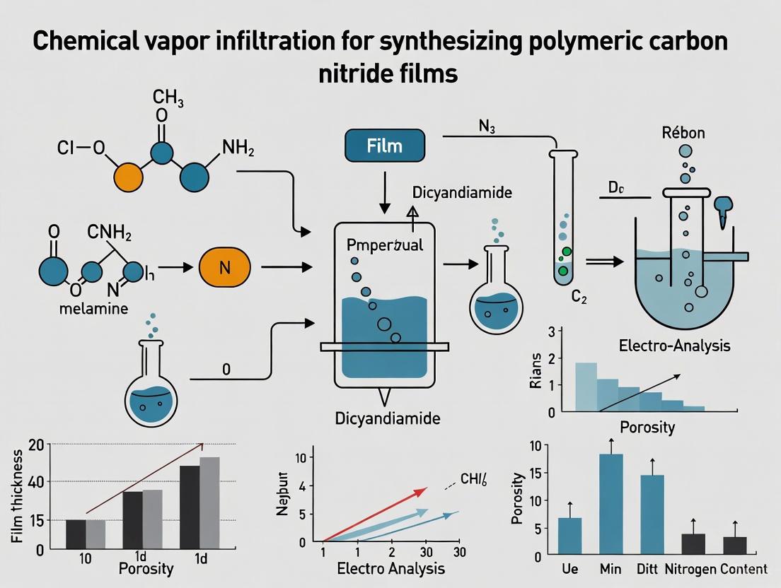
The following diagram illustrates the chemical vapor infiltration process for PCN film fabrication:
Performance and Applications
PCN films fabricated via CVI demonstrate promising functional performances. In photoelectrochemical applications, the best-performing systems exhibit Tafel slopes as low as ≈65 mV/dec and photocurrent density values of ≈1 mA/cm² at 1.6 V vs. RHE for the oxygen evolution reaction (OER) [3]. The direct growth approach ensures optimal PCN/substrate mechanical adhesion and intimate interfacial contact, which are critical for efficient electron transport and long-term stability [3].
The versatility of PCNs extends to diverse applications including:
- Photocatalytic Water Splitting: Hydrogen production through water splitting under visible light illumination [2]
- Environmental Remediation: Photodegradation of organic pollutants and H2O2 production [2] [6]
- Photodetectors: UV and visible light detection with potential for flexible devices [1]
- CO2 Reduction: Conversion of CO2 to chemical feedstocks using solar energy [7]
However, stability considerations must be addressed for long-term applications. Post-mortem analyses of PCN materials after photoelectrochemical testing reveal structural degradation via ring opening, with changes in carbon bonding and the appearance of methylene terminals [7]. This underscores the importance of ongoing research into more condensed and stable PCN structures for durable device operation.
Polymeric carbon nitrides represent a uniquely versatile class of semiconductor materials defined by their two-dimensional, metal-free architecture based on triazine or heptazine building blocks. Their moderate bandgap (~2.7 eV), exceptional physicochemical stability, cost-effectiveness, and molecular-level tunability distinguish them from traditional semiconductors like silicon and III-V compounds. The development of chemical vapor infiltration methods for fabricating PCN films on conductive substrates provides a promising pathway toward high-performance photoelectrochemical devices with excellent interfacial contact and mechanical adhesion. While challenges remain in optimizing charge carrier mobility and long-term operational stability, the distinctive advantages of PCNs position them as compelling materials for next-generation sustainable energy and sensing technologies. Their structural versatility and compatibility with various modification strategies continue to inspire innovative research across multiple disciplines, from fundamental materials science to applied device engineering.
Core Principles and Comparative Analysis
Chemical Vapor Infiltration (CVI) and Chemical Vapor Deposition (CVD) are pivotal gas-phase techniques for fabricating advanced materials, including polymeric carbon nitride (PCN) films. While they share similarities in their use of precursor vapors and chemical reactions, their core principles, objectives, and optimal application landscapes differ significantly.
Chemical Vapor Deposition (CVD) is a process designed for the coating of exposed surfaces. In a typical CVD reaction, volatile precursors are transported in the vapor phase to a substrate, where they undergo chemical reactions and decomposition to form a solid, dense, and adherent film on the substrate surface [8]. The primary objective is to create a uniform, often conformal, coating on the substrate geometry.
Chemical Vapor Infiltration (CVI), in contrast, is a process engineered for the coating of internal surfaces within porous structures. It leverages the molecular-level flexibility and infiltration power of vapor-phase techniques to achieve efficient dispersion of material throughout a porous substrate, not just on its exterior surface [8]. The goal is to modify the internal surface area of a porous monolith, creating a composite material where the deposited phase is distributed within the substrate's porosity.
The following table summarizes the key differentiating factors between these two techniques in the context of PCN film fabrication.
Table 1: Core Principles and Comparative Advantages of CVI and CVD for PCN Fabrication
| Aspect | Chemical Vapor Infiltration (CVI) | Chemical Vapor Deposition (CVD) |
|---|---|---|
| Primary Objective | Coating of internal surfaces of porous substrates (e.g., Ni foam) [8] | Coating of exposed surfaces of planar or simple-shaped substrates (e.g., FTO glass) [8] |
| Process Focus | Infiltration and deposition within the bulk of a porous material [8] | Surface deposition on the exterior of a substrate [8] |
| Resulting Structure | PCN integrated within the porous network, forming a composite electrode [8] | PCN as a thin film on top of the substrate surface [8] |
| Key Advantage | Excellent mechanical adhesion and intimate interfacial contact with high-surface-area substrates [8] | Suitable for creating uniform, dense films on flat or low-porosity substrates [8] |
| Typical Substrates | Porous Ni foam, other 3D scaffolds [8] | Planar FTO (Fluorine-doped Tin Oxide) or ITO (Indium Tin Oxide) glass [8] |
| Reported PCN Film Mass (on Ni Foam) | Varies with precursor amount: ~1-2 mg [8] | Information not specified in the provided search results |
The workflow below illustrates the direct, one-step synthesis of a PCN film on a porous substrate via the CVI process, highlighting its advantage in creating a composite material with integrated functionality.
Experimental Protocols
CVI Protocol for PCN Film Synthesis on Porous Ni Foam
This protocol details a one-step CVI method for the in-situ growth of PCN films on Ni foam, adapted from recent research [8]. This approach overcomes the limitations of two-step powder immobilization methods, which often yield poorly adherent and inhomogeneous deposits.
2.1.1 Primary Reagent Solutions
Table 2: Research Reagent Solutions for CVI of PCN
| Reagent/Material | Function/Description | Specifications/Notes |
|---|---|---|
| Melamine | Precursor compound for PCN synthesis [8] | 99% purity; pre-ground into a fine powder. |
| Porous Ni Foam | Substrate for PCN growth and current collector [8] | Lateral size ~1 x 2 cm²; thickness = 1.7 mm. Requires pre-cleaning. |
| Argon (Ar) Gas | Inert atmosphere for thermal polymerization [8] | High purity; flow rate controlled at 3 L/min. |
| Alumina Crucible | Vessel to contain precursor and hold substrate [8] | Withstands high temperatures (up to 600°C). |
2.1.2 Step-by-Step Procedure
- Substrate Preparation: Clean the Ni foam substrate (approx. 1 x 2 cm²) using an optimized procedure (e.g., sequential sonication in acetone, ethanol, and deionized water) to remove organic and particulate contaminants. Dry thoroughly in an oven or under a stream of inert gas [8].
- Crucible Setup: Fix the cleaned Ni foam substrate on top of a V-shaped alumina crucible. Pre-grind the melamine precursor and place 100-300 mg of it at the bottom of the same crucible, beneath the suspended substrate [8].
- Furnace Assembly: Position the crucible on a stainless-steel susceptor inside a tubular furnace. Cover the setup with a larger alumina vessel to create a semi-closed environment that promotes vapor confinement and infiltration [8].
- Thermal Processing:
- Purge the quartz tube of the furnace with Ar gas at a flow rate of 3 L/min for at least 15 minutes to ensure an oxygen-free environment.
- Initiate the heating program with a ramp rate of 5 °C/min.
- Maintain the reaction at the target temperature (500 °C, 550 °C, or 600 °C) for 2.5 hours under continuous Ar flow. The temperature directly influences the condensation degree of the final PCN film [8].
- Cooling and Harvesting: After the reaction time, turn off the furnace and allow the system to cool down to room temperature naturally under continued Ar flow. Carefully remove the resulting PCN/Ni foam composite electrode. The mass of the deposited PCN can be determined gravimetrically using a microbalance [8].
The reactor configuration for this CVI process is specialized to facilitate the vapor-phase transport and infiltration necessary for coating complex 3D substrates.
Critical Processing Parameters and Their Impact
The properties and performance of the CVI-synthesized PCN films are highly dependent on the synthesis parameters. The following table and diagram detail these key parameters and their specific effects on the final material.
Table 3: Impact of Key CVI Processing Parameters on PCN Film Properties
| Processing Parameter | Impact on PCN Film Properties | Experimental Observations |
|---|---|---|
| Reaction Temperature | Controls the condensation degree and chemical structure of the PCN [8]. | 500°C: Yields melem/melon hybrid structures.550-600°C: Promotes the formation of more condensed, melon-like PCN [8]. |
| Precursor Mass | Affects the mass loading and the morphology of the deposited PCN [8]. | Ranging from 100 mg to 300 mg of melamine allows for control over the deposit's mass and surface morphology, which directly impacts electrochemical performance [8]. |
| Reaction Time | Influences film thickness and crystallinity. | A duration of 2.5 hours is used for complete polymerization and infiltration [8]. |
| Substrate Type | Determines the architecture of the electrode and the deposition mechanism (CVI vs. CVD) [8]. | Porous Ni Foam: Enables CVI, leading to internal coating and composite formation.Planar FTO: Results in classic surface deposition (CVD) [8]. |
Characterization and Performance Analysis
Material Characterization Protocols
To validate the successful synthesis and understand the properties of the CVI-derived PCN films, a multi-faceted characterization approach is recommended.
- X-ray Diffraction (XRD): Perform in a glancing incidence configuration (e.g., θi = 1.0°) to analyze the crystallinity and phase of the PCN films on the substrate. The average crystal size can be estimated using the Scherrer equation [8].
- Field Emission-Scanning Electron Microscopy (FE-SEM): Analyze the surface morphology, uniformity, and thickness of the deposits. Collect both secondary (SE) and backscattered electron (BSE) signals to study the coating's conformity on the complex Ni foam structure [8].
- X-ray Photoelectron Spectroscopy (XPS): Determine the surface elemental composition and chemical states (e.g., C, N, O). Correct binding energy (BE) values for charging by referencing the adventitious C1s peak to 284.8 eV [8].
- Optical Absorption Spectroscopy: Collect spectra in transmittance mode for films on transparent substrates (e.g., FTO). Estimate the band gap (Eg) from Tauc plots, assuming indirect allowed transitions, which is characteristic of PCN materials [8].
Functional Performance in the Oxygen Evolution Reaction (OER)
The CVI-fabricated PCN/Ni foam electrodes demonstrate promising catalytic performance for the Oxygen Evolution Reaction (OER), a critical process for water splitting. Key performance metrics include [8]:
- Tafel Slope: The best-performing PCN electrodes yielded Tafel slopes as low as ≈65 mV/dec, indicating high catalytic efficiency.
- Photocurrent Density: Under white light irradiation (≈100 mW/cm²), photocurrent density values of ≈1 mA/cm² at 1.6 V vs. RHE were achieved.
- Performance Optimization: The OER performance is strongly influenced by the polymerization degree of the PCN, which is controlled by the CVI synthesis temperature. Melem/melon hybrids (formed at lower temperatures) can sometimes exhibit superior performance compared to more condensed melon-like structures due to enhanced reactivity and lower charge carrier recombination [8].
The synthesis of functional heptazine networks from molecular precursors like melamine represents a cornerstone in the development of advanced polymeric carbon nitride (pCN) materials. Within the specific context of chemical vapor infiltration (CVI) for fabricating pCN films, understanding these pathways is not merely academic but crucial for achieving precise control over material properties. The transition from monomeric precursors to extended heptazine networks directly governs the structural, electronic, and ultimately, the functional characteristics of the resulting thin films [3] [9]. This application note delineates the critical precursors and reaction pathways, providing detailed protocols to empower researchers in synthesizing tailored pCN films for applications ranging from photoelectrochemistry to sensing.
The fundamental building block of these materials, the heptazine (or tri-s-triazine) unit, is an electron-deficient, nitrogen-rich heterocyclic system that forms a planar, rigid structure capable of extensive π-conjugation [10] [9]. During thermal condensation, melamine (a triazine) undergoes a series of deamination and condensation reactions, first forming melam and then the heptazine-based melem, before finally polymerizing into a pCN network [9] [11]. The electronic structure evolution from triazine to heptazine is significant, resulting in a more delocalized π-system, a reduced band gap, and frontier orbitals that are uniformly distributed, which enhances photocatalytic activity [9]. Controlling this polymerization pathway, especially when using CVI to grow films on substrates like Ni foam or FTO glass, is paramount for creating adherent, crystalline, and functionally optimal materials [3] [12].
Critical Precursors and Their Characteristics
The formation of heptazine networks can be approached via "bottom-up" thermal condensation or alternative "top-down" strategies. The choice of precursor and synthetic route profoundly impacts the degree of condensation, structural order, and terminal functionality of the final material.
Table 1: Critical Precursors for Heptazine Network Synthesis
| Precursor Name | Molecular Structure | Key Functional Groups | Role in Heptazine Formation | Resulting Intermediate/Product |
|---|---|---|---|---|
| Melamine | Triazine core with three -NH₂ groups | Amino groups (-NH₂) | Fundamental starting material; condenses to form melam and then melem [9] [11]. | Melam → Melem → Polymeric CN |
| Cyanamide / Dicyandiamide | -C≡N, -NH₂ | Nitrile and amino groups | Common precursors for direct thermal polymerization to pCN, often yielding highly cross-linked networks [13]. | Poly(heptazine imide) / pCN |
| Urea | H₂N-(C=O)-NH₂ | Carbonyl and amino groups | Low-cost precursor; decomposes to reactive species that polycondense into pCN [14]. | Melon-like pCN |
| Melem | Heptazine core with three -NH₂ groups | Amino groups (-NH₂) | Fully formed heptazine monomer; polymerization yields more defined pCN structures [9] [11]. | Poly(triazine imide) / pCN |
| Alkali Metal Salts (e.g., NaCl, KCl) | Na⁺, K⁺, Cl⁻ | Ionic | Structure-directing agents; react with melamine or cyanamide to form metastable poly(heptazine imide) salts with high photocatalytic activity [13]. | Metastable PHI Salts |
Analysis of Precursor Pathways
The Bottom-Up Thermal Pathway: The conventional route involves the gradual thermal condensation of melamine. Upon heating to approximately 350°C, melamine condenses into melam, a triazine-based intermediate containing a central 2C–NH (NB) bridging nitrogen [9]. Further heating to around 400°C facilitates the transformation into the first heptazine-based molecule, melem (2,5,8-triamino-tri-s-triazine) [9] [11]. This step marks the critical transition from a triazine to a heptazine electronic structure. Finally, at temperatures exceeding 500°C, melem polymerizes via the condensation of its peripheral amino groups, forming the layered structure of polymeric carbon nitride, often described as melon [3] [9].
The Top-Down Depolymerization Route: A novel and efficient alternative for obtaining the heptazine monomer melem involves the depolymerization of pre-formed bulk pCN. Stirring melamine-derived pCN in concentrated sulfuric acid (95–98%) at 80°C for one hour selectively breaks the C–NH–C bonds bridging the heptazine units, releasing molecular melem without forming oligomers or oxidation products [11]. This method provides high-purity melem on a gram scale without requiring an inert atmosphere, making it an invaluable precursor for subsequent high-quality film fabrication [11].
Alkali Metal-Assisted Synthesis: The thermal reaction of traditional precursors like cyanamide or melamine with alkali metal chlorides (e.g., NaCl, KCl, CsCl) provides a direct pathway to metastable poly(heptazine imide) salts [13]. These salts exhibit a high degree of structural order and, owing to their metastability, demonstrate exceptional photocatalytic activity, with hydrogen evolution rates up to four times higher than benchmark mesoporous graphitic carbon nitride [13].
Chemical Vapor Infiltration for pCN Films
While powder synthesis is straightforward, the fabrication of pCN films with good adhesion to conductive substrates is critical for (photo)electrochemical applications. Chemical Vapor Infiltration (CVI) is a highly effective method for the one-step growth of pCN films, offering superior mechanical adhesion and intimate interfacial contact compared to post-synthesis deposition methods like drop-casting [3] [15].
Detailed CVI Protocol for pCN Film Deposition
This protocol describes the synthesis of pCN films on porous Ni foam or FTO-coated glass substrates, adapted from established methodologies [3].
The Scientist's Toolkit: Essential Materials for CVI
- Porous Ni Foam Substrate: Provides a high-surface-area, conductive 3D scaffold, enhancing catalyst loading and mass transport [3].
- Fluorine-Doped Tin Oxide (FTO) Glass: A standard planar conductive substrate for transparent photoelectrodes [3].
- Alumina Crucible (V-shaped): Holds the precursor and withstands high-temperature conditions.
- Tubular Furnace: Provides a uniform and controllable high-temperature environment.
- Melamine Powder (99%): The vapor-phase precursor for pCN formation [3] [12].
- Inert Gas Supply (Argon or N₂): Creates an oxygen-free atmosphere necessary for controlled pyrolysis and condensation.
Step-by-Step Procedure
- Substrate Preparation: Cut the Ni foam or FTO glass to the desired dimensions (e.g., 1 × 2 cm²). Clean the substrates meticulously using a multi-step process involving sonication in solvents (e.g., acetone, ethanol) and possibly oxygen plasma treatment to ensure a contaminant-free surface for optimal pCN adhesion [3].
- Crucible Preparation: Weigh 100-300 mg of finely ground melamine powder and place it at the bottom of the V-shaped alumina crucible. The amount of precursor directly influences the mass and morphology of the final deposit [3].
- Assembly: Fix the cleaned substrate on top of the crucible, ensuring it is positioned above the melamine powder. Place the crucible inside the tubular furnace.
- CVI Process:
- Purge the quartz tube with an inert gas (e.g., Ar) at a flow rate of 3 L/min for at least 15 minutes to eliminate oxygen.
- Heat the furnace to the target deposition temperature (500–600°C) at a controlled heating rate of 5°C/min.
- Maintain the reaction at the target temperature for 2.5 hours under continuous Ar flow [3].
- Cooling and Collection: After the deposition time, turn off the furnace and allow the system to cool naturally to room temperature under continued Ar flow. Remove the resulting pCN-coated substrate. The mass gain of the deposit can be measured using a microbalance.
CVI Parameter Optimization and Film Characteristics
Table 2: Effect of CVI Parameters on pCN Film Properties
| Process Parameter | Typical Range | Influence on Film Properties | Recommended Value for OER |
|---|---|---|---|
| Deposition Temperature | 500–600°C | Lower (500°C): Less condensed melem/melon hybrids. Higher (600°C): More condensed, melon-like films. Affects band gap and crystallinity [3]. | 550°C [3] |
| Precursor Mass | 100–300 mg | Directly affects the mass loading and thickness of the deposited film. Higher mass leads to thicker, potentially more opaque deposits [3]. | 200 mg (optimizable) |
| Deposition Time | 2.5 hours | Influences film thickness and continuity. Longer times may lead to thicker films but risk pore blockage in porous substrates [3]. | 2.5 hours |
| Substrate Type | Ni Foam, FTO | Ni Foam: High porosity for 3D growth, excellent for electrocatalysis. FTO: Planar, transparent, ideal for photoelectrochemistry [3]. | Ni Foam for OER |
The properties of the CVI-derived pCN films can be finely tuned by adjusting the synthesis parameters. For instance, varying the reaction temperature from 500°C to 600°C allows control over the condensation degree of the pCN, yielding materials ranging from melem/melon hybrids to more fully condensed melon-like systems [3]. This control is crucial, as the polymerization degree directly influences the electronic band structure and, consequently, the electrochemical performance. The best-performing pCN films on Ni foam for the Oxygen Evolution Reaction (OER) have yielded Tafel slopes as low as ≈65 mV/dec and photocurrent density values of ≈1 mA/cm² at 1.6 V vs. RHE [3].
Characterization and Performance Evaluation
Rigorous characterization is essential to correlate the synthetic conditions with the structural and functional properties of the heptazine networks.
Structural and Chemical Analysis:
- X-ray Diffraction (XRD): Identifies the degree of crystallinity and interlayer stacking. A strong peak at ~27° (2θ) is characteristic of the (002) plane, indicating periodic stacking of heptazine layers [3] [12].
- X-ray Photoelectron Spectroscopy (XPS): Determines the elemental composition and bonding states of carbon (C-C, N-C=N) and nitrogen (C-N-C, N-(C)₃, C-N-H) [13] [3]. In-situ XPS can even reveal surface interactions, such as electron density shifts upon water adsorption, which are critical for photocatalytic activation [16].
- Fourier-Transform Infrared (FT-IR) Spectroscopy: Confirms the presence of characteristic vibrational modes of the heptazine ring (~800 cm⁻¹) and C-N heterocycles (1200–1700 cm⁻¹) [13] [11].
Optoelectronic and Functional Properties:
- UV-Vis Absorption Spectroscopy: Determines the optical band gap of the material via Tauc plot analysis. Typical pCN films have an indirect band gap of ~2.7 eV, suitable for visible light absorption [3] [9].
- Photoelectrochemical (PEC) Testing: Evaluates the functional performance of the films, typically in a three-electrode cell setup. Key metrics include photocurrent density under illumination and Tafel slope for electrocatalytic reactions like the OER [3].
Application Notes and Troubleshooting
Note 1: Selecting the Precursor Pathway. For the highest structural order and photocatalytic activity in powder synthesis, the alkali metal-assisted route to form poly(heptazine imide) salts is recommended [13]. For obtaining the pure heptazine monomer as a building block for more advanced structures, the top-down acid depolymerization of bulk pCN is highly efficient [11].
Note 2: Optimizing CVI for Film Quality. To ensure uniform, adherent pCN films via CVI, avoid excessively high heating rates, which can lead to non-uniform precursor vapor pressure and flaky deposits. The use of a porous substrate like Ni foam facilitates superior vapor infiltration and mechanical interlocking compared to planar substrates [3] [15].
Note 3: Enhancing Photocatalytic Mechanism. Recent in-situ studies reveal that water adsorption on the pCN surface causes a critical shift in the valence band position to higher binding energy, effectively increasing the oxidation potential of the material. This "pre-polarization" is a key activation step for artificial photosynthesis [16]. Ensuring good hydrophilicity of your pCN film can therefore enhance its water-splitting performance.
Troubleshooting: Poor Film Adhesion. If the pCN film delaminates from the substrate, the primary cause is often inadequate substrate cleaning. Revisit the cleaning protocol rigorously. As an alternative, consider the dissolution of pCN in polyphosphoric acid (PPA) to create a processable ink for casting composite membranes, which offers excellent mechanical properties due to molecular-level blending with materials like carbon nanotubes [17].
Polymeric carbon nitrides (PCNs) have emerged as a leading class of metal-free photocatalytic platforms for green energy generation and environmental remediation, attracting exponential research interest over the past decade [8]. These materials feature a pseudo-graphitic structure composed of carbon, nitrogen, and hydrogen, with melon-like systems representing some of the most extensively studied variants—formed by variously condensed one-dimensional chains of amine-linked heptazine units that create H-bonded layers [8] [3]. While PCNs can be readily synthesized in powdered form from abundant precursors like melamine, urea, or dicyandiamide, their application in photoelectrochemical systems requires effective fabrication methods for producing PCN films with suitable mechanical stability and modular physicochemical properties [8] [3].
The functional behavior of PCNs is profoundly influenced by two critical structural parameters: their condensation degree and defect architecture. The condensation process involves a cascade of reactions beginning with melamine and progressing through intermediates like melam and melem oligomers before forming melon-like PCN structures [8] [3]. Throughout this process, the modulation of polymerization degree and amino group concentration provides a versatile toolbox for molecular-level engineering of material reactivity [8]. Concurrently, defect engineering has emerged as a powerful strategy to refine the intrinsic properties of semiconductor photocatalysts, enabling precise control over electronic structure, charge dynamics, and active surface sites [18]. Defects in PCNs can manifest as substitutional dopants, interstitial dopants, vacancies, functional groups, and structural disorder, each imparting distinct influences on the material's catalytic behavior [18].
This application note explores the intricate relationship between condensation degree, defect engineering, and the resulting physicochemical properties of PCN materials, with particular emphasis on films synthesized via chemical vapor infiltration (CVI) for photoelectrochemical applications. By providing detailed protocols, data analysis, and mechanistic insights, we aim to equip researchers with the knowledge needed to strategically tailor PCN materials for specific catalytic and electronic applications.
Chemical Vapor Infiltration Protocol for PCN Films
Materials and Equipment
Research Reagent Solutions and Essential Materials
Table 1: Essential materials for CVI synthesis of PCN films
| Material/Reagent | Specifications | Function/Role |
|---|---|---|
| Nickel foam substrate | Lateral size ≈1 × 2 cm²; thickness = 1.7 mm; Ni-4753, RECEMAT BV | Porous, conductive 3D substrate providing high surface area and electrical conductivity |
| FTO-coated glass | Lateral size ≈1 × 2 cm²; FTO layer thickness ≈600 nm; ≈7 Ω/sq | Planar conductive substrate for comparative characterization |
| Melamine powder | 99% purity (Sigma-Aldrich) | Primary precursor for PCN formation |
| Argon gas | High purity, 3 L/min flow rate | Inert atmosphere creation and vapor transport medium |
| Alumina crucible | V-shaped configuration | Precursor container and substrate support |
| Tubular furnace | Carbolite HST 12/200 with quartz tube (inner diameter ≈9.5 cm) | Controlled thermal environment for vapor deposition |
Equipment Setup
The CVI system consists of a tubular furnace equipped with a quartz tube reaction chamber. A V-shaped alumina crucible serves as both the precursor container and substrate support. The substrate (Ni foam or FTO-glass) is fixed atop the crucible, while pre-ground melamine powder is placed at the bottom. The entire assembly is covered with a larger alumina vessel to create a confined reaction environment and positioned on a stainless steel susceptor within the furnace [8] [3].
Step-by-Step Synthesis Procedure
Substrate Preparation: Clean substrates using an optimized procedure to remove surface contaminants. For Ni foam, this typically involves sequential washing with organic solvents, acid treatment, and drying [8] [3].
Precursor Loading: Place 100-300 mg of pre-ground melamine powder (99%) at the bottom of the V-shaped alumina crucible. The specific mass determines final PCN loading and morphology [8] [3].
Substrate Positioning: Fix the cleaned substrate on top of the crucible, ensuring it is securely positioned above the precursor.
Assembly Placement: Position the crucible assembly on a stainless steel susceptor, cover with a second larger alumina vessel, and introduce into the quartz tube of the tubular furnace.
Thermal Processing: Under flowing Ar (rate = 3 L/min), heat the system to the target temperature (500-600°C) at a rate of 5°C/min. Maintain at the deposition temperature for 2.5 hours at atmospheric pressure.
Cooling and Recovery: After deposition, cool samples to room temperature under flowing Ar. Carefully recover the deposited PCN films for characterization [8] [3].
Condensation Degree Control and Characterization
Temperature-Dependent Condensation
The condensation degree of PCN films is primarily controlled through reaction temperature during CVI synthesis. This parameter dictates the progression from partially condensed intermediates to fully formed melon-like structures [8] [3].
Table 2: Temperature-dependent condensation characteristics of PCN films
| Synthesis Temperature (°C) | Primary Condensation Products | Band Gap (eV) | Crystal Size (nm) | Key Structural Features |
|---|---|---|---|---|
| 500 | Melem/melon hybrids | ~2.7 | Smaller | Lower condensation degree, higher amino functionality |
| 550 | Intermediate condensation | 2.7-2.98 | Intermediate | Mixed melem/melon character |
| 600 | Melon-like structures | ~2.98 | Larger | Higher condensation, reduced amino groups |
At 500°C, the resulting PCN films predominantly consist of melem/melon hybrids with lower condensation degrees. As temperature increases to 600°C, more completely condensed melon-like materials form, characterized by extended heptazine networking and reduced amino functionality [8]. This progression significantly impacts the electronic properties, with band gaps increasing to approximately 2.98 eV at higher temperatures due to enhanced crystallinity and structural ordering [19].
Characterization Techniques
X-ray Diffraction (XRD): Performed in glancing incidence configuration (θi = 1.0°) using a CuKα source. The average crystal size is estimated using the Scherrer equation, revealing temperature-dependent crystallinity improvements [8] [3].
Optical Absorption Spectroscopy: Band gap (Eg) values are estimated from Tauc plots [(αhν)1/2 vs. hν], assuming indirect allowed transitions. This analysis demonstrates the widening of band gaps with increasing synthesis temperature [8] [19].
X-ray Photoelectron Spectroscopy (XPS): Using a monochromatized AlKα source, with binding energy correction via adventitious C1s component at 284.8 eV. XPS reveals chemical composition changes, particularly in C-N bonding environments and amino group concentration, corresponding to different condensation degrees [8] [3].
Defect Engineering Strategies and Mechanisms
Defect Classification in PCN Materials
Defect engineering encompasses intentional creation of structural imperfections to modulate material properties. In PCN systems, defects can be categorized into several distinct types [18] [20]:
- Vacancy defects: Missing atoms within the heptazine framework (e.g., nitrogen or carbon vacancies)
- Functional group defects: Edge-functionalization with amino, cyano, or other moieties
- Substitutional dopants: Replacement of carbon or nitrogen with heteroatoms
- Interstitial dopants: Foreign atoms occupying interstitial positions
- Structural disorder: Amorphous regions or stacking faults
Defect-Specific Synthesis Protocols
Amino-Functionalized PCN Synthesis
The introduction of specific edge functional groups provides a powerful means to tailor PCN surface chemistry and electronic properties [21]:
Precursor Preparation: Mix melamine and trichloroisocyanuric acid in 1:2 molar ratio with 150 mL methanol solvent.
Stirring: Magnetically stir at room temperature for approximately 12 hours to obtain dried powders.
Washing: Wash the dry precursor several times with methanol and deionized water.
Thermal Polycondensation: Heat the precursor at 550°C for 4 hours under nitrogen atmosphere with a heating rate of 5°C/min.
Product Recovery: Collect the resulting amino-decorated PCN (PCN-MT) for characterization and application [21].
Cyanamide-Functionalized PCN Synthesis
Cyanamide-functionalized PCN with distinct electronic properties can be prepared through ionothermal treatment [21]:
Starting Material: Begin with amino-decorated PCN (PCN-MT) prepared as described above.
Ionothermal Processing: Heat PCN-MT in KCl/LiCl eutectic mixture at 600°C for 4 hours under nitrogen atmosphere.
Washing and Purification: Wash the resulting material repeatedly with deionized water to remove salt residues.
Drying: Dry at 60°C overnight to obtain cyanamide-enriched PCN (PCN-IT) [21].
Defect-Mediated Property Modulation
The intentional introduction of specific defects profoundly influences PCN electronic structure and catalytic behavior. Amino-functionalized PCN exhibits strong excitonic effects and preferential generation of singlet oxygen (¹O₂), favoring electrophilic attack pathways. In contrast, cyanamide-functionalized PCN demonstrates reduced exciton binding energy, enhanced charge separation, and superoxide radical (·O₂⁻) generation, promoting radical chain reactions [21].
Table 3: Defect-dependent photocatalytic behavior in functionalized PCN
| Defect Type | Excitonic Behavior | Reactive Oxygen Species | Reaction Preference | Application Performance |
|---|---|---|---|---|
| Amino-functionalization | Strong excitonic effects | Preferential ¹O₂ generation | Electrophilic attack on -SH groups | Selective CH₃SH to CH₃SO₃H (84% selectivity) |
| Cyanamide-functionalization | Reduced exciton binding, enhanced charge separation | Dominant ·O₂⁻ production | Radical chain reactions | Selective CH₃SH to H₂SO₄ (82% selectivity) |
Property-Function Relationships in PCN Materials
Electronic Structure Modulation
The condensation degree and defect architecture collectively determine the electronic structure of PCN materials. Higher condensation degrees at elevated temperatures (600°C) yield larger crystalline domains with wider band gaps (~2.98 eV), while lower temperature synthesis (500°C) produces materials with narrower band gaps (~2.7 eV) and higher surface functionality [8] [19]. Defect engineering further fine-tunes these electronic properties, with amino-functionalization increasing exciton binding energy and cyanamide-functionalization promoting charge separation [21].
In-situ near-ambient pressure XPS studies have revealed that water adsorption on carbon nitride surfaces induces significant electronic structure modifications, shifting XPS peaks toward higher binding energies due to electron density donation into hydrogen bonds. This adsorption-activated state exhibits a remarkable 1.04 eV shift of the valence band position to higher binding energies, creating a more favorable electronic configuration for photocatalytic water oxidation [16].
Catalytic Performance Optimization
The strategic combination of condensation control and defect engineering enables precise optimization of PCN materials for specific catalytic applications. For oxygen evolution reaction (OER), the best-performing PCN films fabricated via CVI on Ni foam demonstrate Tafel slopes as low as ≈65 mV/dec and photocurrent density values of ≈1 mA/cm² at 1.6 V vs. RHE [8] [3].
For selective photooxidation reactions, defect engineering enables remarkable control over reaction pathways. Amino-decorated PCN favors oxidation of -SH groups in CH₃SH to form CH₃SO₃H with 84% selectivity, while cyanamide-enriched PCN preferentially breaks the -CH₃ group to produce H₂SO₄ with 82% selectivity [21]. This defect-mediated selectivity stems from the distinct reactive oxygen species generated by each functional group type, directing reaction pathways through fundamentally different mechanisms.
Advanced Characterization Protocols
In-situ Spectroscopic Analysis
Recent advances in characterization methodologies have enabled unprecedented insights into PCN behavior under operational conditions. In-situ near-ambient pressure XPS and NEXAFS techniques allow monitoring of surface interactions during photocatalytic processes [16]:
Experimental Setup: Utilize synchrotron radiation facilities with differentially pumped apertures near the sample surface.
Pressure Conditions: Conduct experiments at 0.2 mbar D₂O vapor pressure to mimic reaction environments while maintaining spectrometer functionality.
Illumination Integration: Employ solar simulator illumination during spectral acquisition to observe photoexcited states.
Data Acquisition: Collect high-resolution spectra of C 1s, N 1s, and valence band regions under dark, D₂O-adsorbed, and illuminated conditions.
This approach has captured stable intermediate structures during photocatalytic water splitting, revealing a proton-coupled electron transfer mechanism where electrons delocalize along conjugated reaction sites while being Coulombically stabilized by protons [16].
Photoelectrochemical Testing
OER electrochemical tests provide critical performance metrics for PCN photoelectrodes [8] [3]:
Electrode Configuration: Use prepared PCN samples as working electrodes, Pt coil as counter electrode, and Hg/HgO (MMO) as reference electrode.
Electrolyte: 0.1 M KOH aqueous solution (pH = 12.9).
Illumination Conditions: Perform tests in dark and under white light LED irradiation (intensity ≈100 mW/cm²).
Data Processing: Convert potential values vs. MMO to the reversible hydrogen electrode (RHE) scale using the Nernst equation.
Key Metrics: Extract Tafel slopes and photocurrent density values at 1.6 V vs. RHE for performance comparison.
The strategic integration of condensation degree control and defect engineering provides a powerful framework for tailoring PCN properties toward specific applications. Through precise manipulation of synthesis parameters—particularly temperature and precursor composition—researchers can direct structural evolution from melem/melon hybrids to fully condensed melon-like systems while introducing specific functional groups that dictate electronic structure and reactive behavior. The protocols and relationships outlined in this application note establish a foundation for rational design of PCN materials optimized for diverse photoelectrochemical and photocatalytic applications, from water splitting to selective organic transformations. As characterization techniques continue to advance, particularly in-situ methodologies under operational conditions, our understanding of structure-function relationships in these versatile materials will further refine our ability to engineer PCNs with precisely tailored properties.
Synthesizing Advanced PCN Films: CVI/CVD Protocols and Cutting-Edge Applications
This document provides detailed application notes and protocols for the one-step synthesis of Polymeric Carbon Nitride (PCN) films via Chemical Vapor Infiltration (CVI). The presented methodology is a cornerstone of a broader thesis focused on advancing CVI for the creation of metal-free, photocatalytically active platforms on both porous and planar substrates. This in-situ growth strategy overcomes the limitations of traditional two-step methods (e.g., spin-coating) by ensuring superior film adhesion, intimate interfacial contact with the substrate, and enhanced mechanical stability, which are critical for photoelectrochemical applications such as the oxygen evolution reaction (OER) in water splitting [3].
Research Reagent Solutions & Essential Materials
The table below catalogs the key materials required for the CVI growth of PCN films.
Table 1: Essential Materials for PCN Film Growth via CVI
| Item Name | Function / Role in the Protocol |
|---|---|
| Melamine | Serves as the abundant and inexpensive precursor compound for the synthesis of polymeric carbon nitrides [3]. |
| Porous Ni Foam | Acts as a conductive, high-surface-area substrate for PCN growth, beneficial for (photo)electrochemical applications [3]. |
| FTO-coated Glass | Provides a planar, conductive substrate for depositions intended for specific characterization techniques or device configurations [3]. |
| Argon (Ar) Gas | Creates an inert atmospheric environment within the tubular furnace during the thermal polymerization process, preventing unwanted oxidation [3]. |
| Alumina Crucible | A high-temperature resistant vessel that holds the melamine precursor and supports the substrate during the CVI process [3]. |
Detailed Experimental Protocol
Substrate Preparation
- Cutting: Cut the Ni foam (or FTO-glass) to the desired lateral dimensions (e.g., 1 cm × 2 cm) [3].
- Cleaning: Subject the substrates to an optimized cleaning procedure to remove organic and particulate contaminants. A typical sequence involves ultrasonic agitation in solvents like acetone, methanol, and isopropanol, followed by rinsing with deionized water [3].
- Drying: Ensure substrates are completely dry before use.
Precursor and Reactor Setup
- Precursor Weighing: Weigh out pre-grinded melamine powder (100, 200, or 300 mg) and place it at the bottom of a V-shaped alumina crucible [3].
- Substrate Mounting: Fix the cleaned substrate on top of the crucible, ensuring it is positioned to intercept the vaporized precursor.
- Reactor Assembly: Position the crucible on a stainless-steel susceptor, cover it with a larger alumina vessel to contain the vapor, and introduce the entire assembly into a quartz tube located inside a tubular furnace [3].
CVI Growth of PCN Films
- Environment Purge: Seal the system and purge with flowing Argon gas to establish an inert atmosphere.
- Thermal Processing: Initiate the heating program with a rate of 5 °C/min. Maintain the furnace at the target reaction temperature (500 °C, 550 °C, or 600 °C) for a duration of 2.5 hours under a continuous Ar flow (rate = 3 L/min) and at atmospheric pressure [3].
- Cooling: After the deposition time has elapsed, turn off the furnace and allow the system to cool down to room temperature under the flowing Ar atmosphere.
- Mass Measurement: Carefully remove the sample and measure the mass of the deposited PCN film using a microbalance [3].
Data Presentation: Synthesis Parameters and Outcomes
The following tables summarize key quantitative data from the protocol, illustrating how different parameters influence the final material's properties.
Table 2: Influence of CVI Process Parameters on PCN Film Properties [3]
| Process Parameter | Varied Conditions | Observed Influence on PCN Film |
|---|---|---|
| Reaction Temperature | 500 °C, 550 °C, 600 °C | Controls the condensation degree, yielding materials ranging from melem/melon hybrids to melon-like PCN. |
| Precursor Mass | 100 mg, 200 mg, 300 mg | Directly affects the mass loading and morphology of the obtained PCN deposits. |
| Substrate Type | Porous Ni Foam, FTO-glass | Ni foam offers high porosity and conductivity; FTO allows for transparent electrode fabrication. The method is transferable. |
Table 3: Functional Performance of the Resulting PCN Photoelectrodes [3]
| Performance Metric | Value for Best-Performing System | Test Conditions |
|---|---|---|
| OER Tafel Slope | ≈65 mV/dec | Towards the Oxygen Evolution Reaction (OER). |
| Photocurrent Density | ≈1 mA/cm² | Measured at 1.6 V vs. RHE (Reversible Hydrogen Electrode). |
Workflow and Logical Relationship Diagram
The diagram below visualizes the logical sequence and decision points in the CVI protocol for PCN film growth.
Application Notes
The integration of Rapid Thermal Processing (RTP) and Field-Enhanced Chemical Vapor Deposition (FE-CVD) represents a significant advancement in the fabrication of high-quality functional films, such as polymeric carbon nitride (pCN), for applications in optoelectronics, catalysis, and biomedical devices. These techniques enable precise control over film morphology, crystallinity, and composition at the nanoscale.
Rapid Thermal Processing (RTP) in pCN Fabrication
RTP utilizes high-intensity lamps for rapid heating and cooling cycles (>100 °C/second), allowing for the synthesis of materials with tailored properties and minimized thermal budget [22]. In the context of pCN films, a developed rapid CVD process leveraging RTP principles can produce smooth, layered pCN films in just 3 minutes, a significant reduction from the hours required by conventional methods [12].
- Process Control: The RTP-CVD synthesis of pCN is typically performed in air at temperatures ranging from 550 °C to 625 °C [12].
- Film Characteristics: This technique produces polycrystalline films with thicknesses between 830 nm and 1547 nm, where crystallites within the layers are oriented parallel to the substrate surface [12]. The surface roughness is remarkably low, reported to be less than 4–6 nm [12].
- Material Properties: The films exhibit high transparency in the visible range. The rapid synthesis directly influences the material's condensation degree, which in turn affects its optical and electronic properties, making it promising for electronic and optoelectronic applications [12].
Table 1: Characteristics of pCN Films Fabricated via Rapid CVD (RTP-based)
| Parameter | Range/Value | Impact/Note |
|---|---|---|
| Deposition Temperature | 550 °C - 625 °C | Performed in air [12] |
| Process Duration | ~3 minutes | Drastic reduction from conventional methods [12] |
| Film Thickness | 830 nm - 1547 nm | Convex function of temperature [12] |
| Surface Roughness | < 4-6 nm | Ensures smooth, uniform layers [12] |
| Refractive Index | 2.50 - 3.25 (visible range) | Determined from optical transmission [12] |
| Photoluminescence Lifetime | 2.3 - 2.6 ns | For high-energy carrier recombination [12] |
Field-Enhanced Chemical Vapor Deposition (FE-CVD)
FE-CVD employs external fields—such as plasma, photo-radiation, electric, or magnetic fields—to influence fundamental steps in the deposition process [23]. These fields act as extrinsic processing parameters that can:
- Lower Process Temperature: External energy input can decompose precursors without relying solely on high thermal energy, enabling deposition on temperature-sensitive substrates [24] [23].
- Control Nucleation and Growth: Fields can impact nucleation density, grain growth, texture, and phase formation, leading to films with superior density, anisotropy, and kinetic stability [23].
- Expand Accessible Materials: By providing alternative reaction pathways, FE-CVD can facilitate the formation of specific phases that are difficult to achieve thermally [23].
This approach offers new insights and directions for developing high-fidelity functional films and coatings [23].
Experimental Protocols
Protocol 1: Rapid CVD of Polymeric Carbon Nitride Films
This protocol details the synthesis of pCN thin films on glass or silicon substrates using a rapid CVD method informed by RTP principles [12].
Research Reagent Solutions
Table 2: Essential Materials for Rapid pCN CVD
| Item | Function | Specification/Note |
|---|---|---|
| Melamine Precursor | Carbon and nitrogen source for pCN formation | Purity ≥ 99% [12] |
| Porous Membrane | Holds precursor; allows vapor passage | Sintered glass, ~100 μm pore diameter [12] |
| Substrate | Film growth surface | Glass slides or SiO2/Si wafers [12] |
| RTP/CVD System | Provides controlled high-temperature environment | Fast heating capability (e.g., ramp > 100 °C/s) [22] |
Procedure
Precursor and Substrate Preparation:
Reactor Setup:
- Assemble the reactor, ensuring a small, defined volume between the precursor and the substrate to minimize the vapor diffusion path [12].
- Secure the setup and ensure the reactor is sealed.
Rapid Thermal Processing & Deposition:
- Place the entire reactor assembly into a preheated furnace at the target deposition temperature (550 °C - 625 °C) [12].
- Maintain the temperature for a short duration (3 minutes). During this time, the melamine sublimates, infiltrates the chamber, and condenses on the substrate to form a pCN film [12].
Cooling and Sample Retrieval:
- After the deposition time, remove the reactor from the furnace.
- Allow it to cool naturally to room temperature.
- Carefully retrieve the substrate with the deposited pCN film.
Workflow Visualization
Protocol 2: General Framework for Field-Enhanced CVD
This protocol outlines a generic workflow for integrating external fields into a standard CVD process, adaptable for various materials systems [23].
Research Reagent Solutions
Table 3: Key Components for a Field-Enhanced CVD System
| Item | Function | Specification/Note |
|---|---|---|
| Volatile Precursor(s) | Source of deposition material | Varies by target material (e.g., AlCl₃, ZrCl₄) [24] |
| Substrate & Heater | Surface for film growth; provides thermal energy | May require specific chuck for field application [23] |
| Field Generation Unit | Applies external energy (plasma, light, electric, magnetic) | E.g., RF plasma source, UV lamps, electrode setup [23] |
| Mass Flow Controllers | Regulate precursor and carrier gas flow | High-precision for reproducible experiments [24] |
| Vacuum System | Controls chamber pressure | Enables Low-Pressure (LP) and Ultra-High Vacuum (UHVCVD) operation [22] |
Procedure
System Configuration:
- Configure the CVD reactor for the intended field enhancement (e.g., install electrodes for electric fields, plasma source, or UV lamp array) [23].
- Ensure all field-generation components are compatible and safe for the planned operational conditions (temperature, pressure).
Substrate Loading and Precursor Introduction:
Field-Enhanced Deposition:
- Introduce the volatile precursor into the reaction chamber [24].
- Activate the external field (e.g., ignite plasma, switch on UV source, apply electric bias) to initiate or enhance the decomposition of precursors and surface reactions [23].
- Maintain the deposition parameters (temperature, pressure, field power, gas flows) for the duration required to achieve the target film thickness.
Process Termination and Sample Unloading:
- Sequentially switch off the precursor flow, the external field, and the substrate heater.
- Allow the system to cool under continuous gas flow or vacuum.
- Vent the chamber and retrieve the deposited sample.
Workflow Visualization
The Scientist's Toolkit
Table 4: Essential Research Reagent Solutions for Advanced CVD
| Category | Item | Function in Fabrication |
|---|---|---|
| Precursor Materials | Metal-organic compounds, halides | Provide volatile source of target material (e.g., Al, Zr) for film formation [24]. |
| Thermal Processing Equipment | RTP/RTA Systems | Provide rapid heating/cooling (>100 °C/s) for controlled crystallization and annealing [22]. |
| Field Enhancement Tools | Plasma Sources, UV Lamps | Supply external energy to decompose precursors, enabling low-temperature growth and unique phases [23]. |
| Process Control Software | CVDWinPrC | Enables real-time process control, data logging, and automated recipe execution for reproducibility [22]. |
| Gas Handling & Safety | Mass Flow Controllers, Filtered Gas Lines | Ensure high-purity, controlled delivery of precursors and reactive gases; embedded safety protocols [22]. |
Polymeric carbon nitride (PCN) has emerged as a leading metal-free photocatalyst for solar-driven hydrogen production, offering a sustainable pathway for addressing the global energy crisis [25]. These materials, characterized by a pseudo-graphitic structure comprising carbon, nitrogen, and hydrogen, exhibit exceptional thermal and chemical stability, suitable visible light absorption, and favorable band edge positions for driving various photocatalytic reactions [3] [26]. Despite these advantages, pristine PCN suffers from inherent limitations including rapid charge carrier recombination, limited visible-light utilization, and insufficient oxidative capability for efficient oxygen evolution reaction (OER)—the bottleneck process in overall water splitting [25].
Recent advances in material engineering have demonstrated that the fabrication of PCN films with controlled properties is crucial for unlocking their potential in photoelectrochemical applications [3]. In the context of a broader thesis on chemical vapor infiltration (CVI) for PCN films, this application note provides detailed protocols and performance data for developing high-performance PCN-based photoelectrodes specifically tailored for OER and overall water splitting applications.
Performance Benchmarking of PCN-Based Photoelectrodes
The photoelectrochemical performance of PCN-based materials varies significantly based on synthesis methods, structural modifications, and experimental conditions. The following table summarizes key performance metrics for recently developed PCN photoelectrodes in OER and water splitting applications.
Table 1: Performance metrics of recently developed PCN-based photoelectrodes for OER and water splitting
| Material Architecture | Synthesis Method | Performance Metrics | Experimental Conditions | Reference |
|---|---|---|---|---|
| PCN on Ni foam (melem/melon hybrid) | Chemical Vapor Infiltration (CVI) | Tafel slope: ≈65 mV/decPhotocurrent density: ≈1 mA/cm² at 1.6 V vs. RHE | OER test, 1.6 V vs. RHE | [3] |
| Yttrium-doped CNGO film | Doctor-blading & calcination | Photocurrent density: 275 ± 10 μA cm⁻²Faradaic efficiency: 90%Stability: 10 hours | Alkaline medium, water oxidation | [27] |
| PTI-LiCa nanoplates (with exciton dissociation) | Lattice engineering with LiCl/CaCl₂ template | OWS activity: ~5x enhancement vs. conventional PTI | Photocatalytic overall water splitting | [28] |
| NiFe₂O₄ catalyst (AEMWE) | Not specified (in-house) | Low overpotential, high performance at 60°C | AEMWE half-cell, 60°C, flowing electrolyte | [29] |
Table 2: Influence of CVI synthesis parameters on PCN film properties and OER performance [3]
| Synthesis Parameter | Variation Range | Impact on PCN Film Properties | Effect on OER Performance |
|---|---|---|---|
| Reaction Temperature | 500°C to 600°C | Controls condensation degree: melem/melon hybrids (lower T) → melon-like materials (higher T) | Optimal performance at intermediate temperatures with tailored band structures |
| Precursor Amount | 100-300 mg melamine | Directly affects deposit mass and morphological features | Higher mass loading can improve activity up to an optimal point |
| Deposition Time | 2.5 hours | Determines film thickness and substrate coverage | Ensures continuous, adherent films for efficient charge transport |
| Substrate Type | Ni foam, FTO-glass | Porous Ni foam enables high surface area and efficient gas release | Enhanced current densities due to better mass transport and conductivity |
Experimental Protocols
CVI Synthesis of PCN Films on Porous Substrates
Reagents and Materials:
- Melamine (99% purity, Sigma-Aldrich)
- Ni foam substrates (1.7 mm thickness, RECEMAT BV)
- FTO-coated glass substrates (≈7 Ω/sq, Sigma-Aldrich)
- Argon gas (high purity, 99.999%)
- V-shaped alumina crucible
- Ethanol and deionized water for cleaning
Equipment:
- Tubular furnace (e.g., Carbolite HST 12/200) with quartz tube (inner diameter ≈ 9.5 cm)
- Mettler Toledo XS105 DualRange microbalance
- Glove box for sample preparation (optional)
Procedure:
- Substrate Preparation: Cut Ni foam or FTO substrates to desired dimensions (e.g., 1 × 2 cm²). Clean substrates using an optimized procedure involving sequential sonication in ethanol and deionized water for 15 minutes each, then dry under nitrogen stream [3].
- Precursor Loading: Place pre-ground melamine powder (100-300 mg) at the bottom of a V-shaped alumina crucible. Fix the cleaned substrate on top of the crucible, ensuring it faces the precursor material.
- CVI Reaction Setup: Position the crucible on a stainless steel susceptor and cover with a larger alumina vessel to create a confined environment. Transfer the assembly to the quartz tube of the tubular furnace.
- Thermal Processing: Purge the system with Ar gas (flow rate = 3 L/min) for 15 minutes to remove oxygen. Heat the system to the target temperature (500-600°C) at a rate of 5°C/min under continuous Ar flow and maintain for 2.5 hours at atmospheric pressure.
- Cooling and Collection: After the reaction time, cool the system naturally to room temperature under flowing Ar. Carefully remove the deposited samples and determine the mass using a microbalance.
Quality Control:
- The deposited PCN films should appear as homogeneous yellow to brownish deposits on the substrate surface.
- Adhesion can be tested by gentle tape test or mild sonication.
- Mass loading typically ranges from 0.5-2.0 mg/cm² depending on precursor amount and temperature.
Photoelectrochemical Characterization for OER
Reagents and Materials:
- Potassium hydroxide (KOH, 0.1 M or 1.0 M) or potassium phosphate buffer (pH 7) as electrolyte
- High-purity water (Milli-Q, 18.2 MΩ·cm)
- Oxygen or nitrogen gas for electrolyte purging
Equipment:
- Potentiostat/Galvanostat workstation (e.g., Autolab PGSTAT204)
- Standard three-electrode electrochemical cell
- Platinum coil as counter electrode
- Hg/HgO reference electrode (for alkaline media) or Ag/AgCl reference electrode
- LED or Xe lamp light source with appropriate filters (AM 1.5G filter recommended)
- Water-cooling system for temperature control (if performing temperature-dependent studies)
Procedure:
- Electrode Preparation: Connect the PCN-deposited substrate (working electrode) to the potentiostat using a suitable electrode holder, ensuring good electrical contact while exposing a defined geometric area (typically 0.5-1.0 cm²) to the electrolyte.
- Cell Assembly: Fill the electrochemical cell with electrolyte (e.g., 0.1 M KOH). Place the reference electrode close to the working electrode surface and position the counter electrode appropriately. Purge the electrolyte with oxygen or nitrogen for at least 20 minutes before measurements, depending on the experiment.
- Dark/Light Measurements: Conduct linear sweep voltammetry from low to high potential (e.g., 0.8 to 1.8 V vs. RHE) at a scan rate of 5-20 mV/s, first in the dark then under illumination. For chronoamperometry, apply a constant potential (e.g., 1.6 V vs. RHE) and record the current response over time with periodic light on/off cycles.
- Tafel Analysis: Plot the overpotential (η) against the logarithm of the current density (log j) derived from the steady-state current in the polarization curve. Fit the linear region to obtain the Tafel slope using the equation: η = a + b log j, where b is the Tafel slope.
- Stability Testing: Perform chronoamperometry at a fixed potential (e.g., 1.6 V vs. RHE) for extended periods (several hours) while monitoring current decay. Calculate the Faradaic efficiency by comparing the measured oxygen evolution with theoretically predicted values based on total charge passed.
Data Analysis:
- Convert potentials to the reversible hydrogen electrode (RHE) scale using the equation: E(RHE) = E(ref) + 0.059 × pH + E°(ref)
- Calculate photocurrent density as the difference between light and dark currents at the same potential
- For incident photon-to-current efficiency (IPCE) measurements, use monochromatic light sources and calculate using: IPCE = (1240 × jphoto)/(λ × Pin) × 100%, where jphoto is photocurrent density (mA/cm²), λ is wavelength (nm), and Pin is incident light power density (mW/cm²)
The Scientist's Toolkit: Essential Research Reagents and Materials
Table 3: Key research reagents and materials for PCN-based photoelectrode development
| Reagent/Material | Function/Application | Examples/Specifications |
|---|---|---|
| Carbon Nitride Precursors | Source for PCN synthesis through thermal polycondensation | Melamine (99%), urea, dicyandiamide, supramolecular complexes |
| Porous Substrates | 3D scaffold for catalyst deposition enhancing surface area and mass transport | Ni foam (4753 type), FTO-coated glass (≈7 Ω/sq), carbon paper |
| Dopant Sources | Modifying electronic structure and introducing active sites | Yttrium acetate (for Y-doping), other metal salts (Fe, Co, Ni) |
| Eutectic Salt Mixtures | Template for crystalline PTI synthesis and morphology control | LiCl/KCl, LiCl/CaCl₂ for PTI nanoplates with lattice engineering [28] |
| Electrochemical Electrolytes | Medium for charge transport during PEC measurements | KOH (0.1-1.0 M for alkaline), phosphate buffers (neutral pH) |
| Reference Electrodes | Providing stable potential reference in 3-electrode setups | Hg/HgO (alkaline media), Ag/AgCl (neutral/acidic media) |
| Counter Electrodes | Completing the electrical circuit in PEC cells | Platinum coil/mesh, carbon rods |
CVI Synthesis Workflow for PCN Photoelectrodes
The following diagram illustrates the optimized chemical vapor infiltration process for fabricating high-performance PCN photoelectrodes, integrating the key parameters and characterization steps detailed in the protocols.
CVI Synthesis Workflow. This diagram outlines the optimized chemical vapor infiltration process for fabricating high-performance PCN photoelectrodes, highlighting the interconnected phases from precursor preparation to functional characterization.
The protocols and performance data presented in this application note demonstrate the significant potential of CVI-synthesized PCN films as efficient photoelectrodes for OER and overall water splitting. The ability to control material properties through CVI parameters such as temperature, precursor amount, and substrate selection provides a powerful toolbox for optimizing photoelectrochemical performance.
Future development in this field should focus on several key areas: (1) further optimization of the CVI process to enhance PCN loading and control over molecular structure; (2) exploration of advanced dopants and co-catalysts to improve charge separation and surface reaction kinetics; (3) development of hybrid architectures combining PCN with other semiconductor materials to extend light absorption and enhance stability; and (4) scaling up the CVI process for manufacturing large-area photoelectrodes suitable for commercial applications.
The integration of PCN films into complete water-splitting systems represents the ultimate goal, requiring careful matching with suitable hydrogen evolution catalysts and membrane assembly technologies. The protocols outlined herein provide a solid foundation for advancing toward these objectives in the ongoing research on chemical vapor infiltration for polymeric carbon nitride films.
Polymeric carbon nitride (PCN) has emerged as a versatile metal-free photocatalyst, attracting significant attention for applications in green energy generation and environmental remediation [3]. This interest stems from its appealing characteristics, including a visible-light-active bandgap (≈2.7 eV), high chemical and thermal stability, and the ability to be synthesized from abundant, non-toxic precursors [3] [12]. The exploration of advanced material fabrication techniques, such as chemical vapor infiltration (CVI), has enabled the synthesis of robust PCN films, moving beyond traditional powdered forms and opening new avenues for creating structured photocatalytic devices [3].
Framed within a broader thesis on chemical vapor infiltration for PCN films, this article details the application of these advanced photocatalytic platforms in two critical domains: pharmaceutical synthesis and environmental organic oxidation. Photoredox catalysis utilizing visible light provides a powerful, sustainable tool for organic synthesis, enabling novel reaction pathways under mild conditions without the need for high-energy UV light or harsh reagents [30] [31]. Concurrently, these materials offer promising solutions for water purification and the degradation of organic pollutants, leveraging solar energy for environmental management [31]. The following sections provide a detailed examination of material properties, specific application protocols, and the experimental workflows that underpin this technology.
Polymeric Carbon Nitride Films via Chemical Vapor Infiltration
Material Synthesis and Key Characteristics
The chemical vapor infiltration (CVI) process represents a direct, in-situ route for growing adherent PCN films on various substrates, overcoming the limitations of powder-based immobilization methods such as poor mechanical stability and weak adhesion [3]. In a proof-of-concept study, PCN was successfully grown on porous Ni foam and FTO-coated glass substrates. This was achieved by placing the substrate above an alumina crucible containing 100-300 mg of ground melamine precursor and heating in a tubular furnace at atmospheric pressure under flowing Ar (3 L/min) for 2.5 hours [3].
A critical feature of this synthesis route is the ability to tailor the material's condensation degree and chemico-physical properties by modulating the reaction temperature. Lower temperatures (e.g., 500°C) yield melem/melon hybrids, while higher temperatures (e.g., 600°C) promote the formation of melon-like materials [3]. This control directly influences the resulting electronic and catalytic properties of the film.
Table 1: Control of PCN Film Properties via CVI Synthesis Parameters
| Synthesis Parameter | Variation Range | Impact on PCN Film Properties |
|---|---|---|
| Reaction Temperature | 500°C, 550°C, 600°C | Determines condensation degree: from melem/melon hybrids (lower temp) to melon-like systems (higher temp) [3]. |
| Precursor Mass | 100 mg, 200 mg, 300 mg | Directly affects the mass loading and morphological features of the final deposit on the substrate [3]. |
| Substrate | Ni Foam, FTO-coated Glass | Enables application in different device architectures; Ni foam offers high porosity and conductivity for (photo)electrochemistry [3]. |
The optical and electronic properties of PCN films are crucial for their function. Films fabricated by rapid CVD (3-10 minutes) at 550-625°C are smooth, layered, and highly transparent in the visible range [12]. These films exhibit a high refractive index (2.50–3.25) and an extinction coefficient of 0.1–0.4, which vary with deposition temperature [12]. The band gap, typically around 2.7 eV, is suitable for visible light absorption, with the exact position of the valence and conduction bands enabling various redox reactions [3] [16].
The Scientist's Toolkit: Essential Research Reagents and Materials
Table 2: Key Reagent Solutions and Materials for PCN CVI and Photocatalysis
| Reagent/Material | Function/Description | Application Context |
|---|---|---|
| Melamine (C₃H₆N₆) | Nitrogen-rich precursor for PCN synthesis; undergoes thermal polycondensation [3] [12]. | Standard precursor for CVI and CVD growth of carbon nitride films. |
| Porous Ni Foam | 3D conductive substrate; provides high surface area, porosity, and excellent mechanical support for PCN growth [3]. | Preferred substrate for photoelectrochemical electrodes (e.g., OER). |
| FTO-coated Glass | Transparent conductive oxide (TCO) substrate; allows light penetration for front-side illumination in photoelectrochemical cells [3]. | Substrate for optoelectronic characterization and transparent electrodes. |
| Argon (Ar) Gas | Inert carrier gas; creates an oxygen-free atmosphere during thermal polymerization, preventing precursor oxidation [3]. | Essential atmosphere for controlled CVI/CVD synthesis. |
| Methyltrichlorosilane (MTS) | Common preceramic gaseous precursor; decomposes to form a silicon carbide (SiC) matrix in composite materials [15]. | Used in CVI for fabricating ceramic matrix composites (e.g., SiCf/SiC). |
Application Notes and Protocols
Protocol 1: Fabrication of PCN Films via CVI for Photoelectrocatalysis
Application: Fabrication of robust, adherent PCN photoelectrodes for reactions such as the Oxygen Evolution Reaction (OER), a critical process for water splitting and energy storage [3].
Materials:
- Substrates: Ni foam (e.g., 1 × 2 cm², thickness 1.7 mm) or FTO-coated glass.
- Precursor: Melamine powder (99%), pre-ground.
- Equipment: Tubular furnace, alumina crucibles, Ar gas supply, microbalance.
Procedure:
- Substrate Preparation: Clean the substrates (Ni foam or FTO) using an optimized procedure to remove surface contaminants [3].
- Crucible Setup: Fix the cleaned substrate on top of a V-shaped alumina crucible. Place 100-300 mg of ground melamine powder at the bottom of the same crucible.
- Furnace Loading: Position the crucible assembly on a susceptor inside the quartz tube of the furnace. Cover it with a larger alumina vessel to contain vapor.
- CVI Process:
- Purge the system with Ar gas.
- Heat the furnace to the target temperature (500–600°C) at a controlled ramp rate of 5°C/min under a constant Ar flow of 3 L/min.
- Maintain the deposition temperature for 2.5 hours to allow for precursor sublimation, vapor infiltration, and in-situ polymerization on the substrate.
- Cooling and Harvesting: After the deposition time, cool the system to room temperature under continued Ar flow. Carefully remove the coated substrate and measure the deposit mass using a microbalance [3].
Performance Metrics: The best-performing PCN/Ni foam electrodes from this protocol have demonstrated Tafel slopes as low as ≈65 mV/dec and photocurrent densities of ≈1 mA/cm² at 1.6 V vs. RHE for the OER [3].
Protocol 2: Photocatalytic Organic Transformation for Pharmaceutical Synthesis
Application: Utilizing PCN-based photocatalysts for sustainable organic synthesis, including C–C and C–heteroatom bond formations, which are pivotal in drug development and fine chemical manufacturing [31] [32].
Materials:
- Photocatalyst: PCN film on an inert substrate (e.g., FTO) or PCN powders in suspension.
- Organic substrates and reagents (varies by specific reaction).
- Solvents (often green solvents like water or ethanol).
- Light Source: Visible light source (e.g., blue LEDs, solar simulator).
- Reaction vessel suitable for irradiation.
Procedure:
- System Setup: Place the PCN photocatalyst and the organic reaction mixture in an appropriate vessel. For films, the setup may be a flow reactor; for powders, a slurry batch reactor is used.
- Deaeration (if required): Purge the reaction mixture with an inert gas (e.g., N₂ or Ar) to remove oxygen, which can quench reactive radical intermediates.
- Irradiation: Stir the mixture under visible light irradiation at or near room temperature. The light intensity and wavelength should be controlled.
- Reaction Monitoring: Monitor reaction progress using standard analytical techniques (e.g., TLC, GC-MS, HPLC).
- Product Isolation: Upon completion, separate the photocatalyst (by filtration for powders, or by simple removal for films) and purify the product using standard techniques (e.g., extraction, chromatography) [31] [32].
Key Advantages: This protocol highlights the green chemistry principles of photoredox catalysis: using light as a traceless reagent, operating under mild conditions, and often achieving high selectivity, which simplifies product purification and reduces waste [31].
Experimental Workflows and Mechanistic Pathways
The experimental workflow for developing and applying a CVI-fabricated PCN photocatalytic device integrates material synthesis, characterization, and functional testing, as outlined below.
The mechanism of photocatalysis for PCN materials, particularly in complex reactions like water splitting, involves critical steps of surface activation and proton-coupled electron transfer. Recent in-situ spectroscopic studies have revealed that water adsorption itself plays a pivotal role by altering the surface electron density of the semiconductor, creating an activated state primed for catalysis [16]. The following diagram illustrates this mechanism.
The integration of chemical vapor infiltration for the synthesis of structured polymeric carbon nitride films represents a significant advancement in the field of photocatalysis. These metal-free, stable, and efficient platforms provide a versatile foundation for addressing key challenges in both sustainable pharmaceutical synthesis and environmental remediation. The detailed application notes and protocols provided herein offer researchers and drug development professionals a roadmap for implementing these systems, from material fabrication to functional testing. As the fundamental understanding of mechanisms, such as surface activation and proton-coupled electron transfer, continues to deepen through advanced in-situ techniques [16], the rational design of next-generation PCN-based photocatalysts with enhanced activity and selectivity will undoubtedly accelerate, pushing the frontiers of green chemistry and technology.
Optimizing PCN Film Quality: Solving Deposition Challenges and Enhancing Performance
In the chemical vapor infiltration (CVI) of polymeric carbon nitride (pCN) films, achieving uniform deposition throughout porous substrates represents a significant materials engineering challenge. The CVI process, derived from chemical vapor deposition (CVD), involves infiltrating gaseous precursors into porous structures where chemical reactions deposit solid material within the internal pore network [33]. For pCN films, this typically involves precursors such as melamine, which undergo thermal polymerization to form the characteristic pseudo-graphitic structure of carbon nitride [8]. However, two interconnected phenomena frequently compromise deposition uniformity: premature pore blockage and non-uniform surface roughness.
Pore blockage occurs when deposition proceeds more rapidly near pore openings, effectively sealing the entrance before the interior volumes are fully densified [33]. This issue is intrinsically linked to surface roughness, as non-uniform deposition manifests as variable topography on both microscopic and macroscopic scales. In pCN film synthesis, these challenges are particularly acute due to the complex reaction pathways involved in the polymerization process and the sensitivity of deposition kinetics to local temperature and concentration gradients [34] [8]. The following sections detail specific strategies to overcome these limitations, with particular emphasis on their application to pCN films for advanced energy and separation applications.
CVI Process Variants and Uniformity Control Strategies
Different CVI approaches have been developed to mitigate pore blockage and enhance deposition uniformity, each employing distinct strategies to control the deposition kinetics and mass transport phenomena.
Table 1: Comparison of CVI Process Variants for Uniform Deposition
| Process Variant | Key Operating Principle | Advantages for Uniformity | Limitations | Applicability to pCN Films |
|---|---|---|---|---|
| Isothermal CVI (I-CVI) | Low temperature & pressure in isothermal reactor to slow surface reaction rates [33]. | High flexibility; suitable for multiple complex shapes simultaneously [33]. | Very long processing times (several hundred hours); intermediate machining often needed [33] [35]. | Demonstrated for pCN using melamine precursor in hot-wall reactors [34] [8]. |
| Temperature/Pressure Gradient CVI (F-CVI) | Temperature gradient applied across preform; reactants injected from cold side [33]. | Significantly shortened densification times; moves densification front controllably [33]. | Low flexibility; requires specific fixturing per preform; not ideal for complex shapes [33]. | Potentially beneficial for thick pCN deposits on simpler substrate geometries. |
| Pressure-Pulsed CVI (P-CVI) | Cyclic evacuation and reactant injection into the reactor chamber [33]. | Prevents product inhibition; enables nano-scale layered structures [33]. | More complex facility requirements; still largely experimental [33]. | Ideal for engineering complex pCN layered architectures. |
| Film Boiling (Calefaction) | Preform immersed in boiling liquid precursor; steep radial temperature gradient [33]. | Extremely efficient mass transfer; very short densification times (≈1 day) [33]. | Limited flexibility; requires susceptor for each preform [33]. | Not yet reported for pCN films. |
Tailored Thermal and Pressure Environments
Strategic management of thermal and pressure parameters provides the most direct method for controlling deposition uniformity. The Isothermal CVI (I-CVI) method, while time-consuming, offers a proven approach for pCN films by maintaining low temperatures (typically 500-600°C for melamine-based pCN) and reduced pressures to decrease reaction rates, thereby favoring in-depth infiltration over surface deposition [33] [8]. This allows the gaseous precursors to diffuse deeper into the pore structure before decomposing and depositing solid material.
The Temperature/Pressure Gradient CVI (F-CVI) method represents a more aggressive strategy, particularly useful for thicker deposits. By creating a controlled temperature gradient across the substrate, deposition initiates preferentially at the hotter face. As this region densifies, the hot zone progressively moves toward the colder regions, systematically infiltrating the preform [33]. Although this method requires specialized equipment, it can reduce processing times by nearly an order of magnitude compared to conventional I-CVI.
Advanced Reactor Engineering and Process Cycling
Pressure-pulsed CVI (P-CVI) introduces temporal variation to process parameters, cycling between evacuation and reactant injection phases. This periodic renewal of the reactant atmosphere within the pore network serves two critical functions: it removes reaction by-products that may inhibit further deposition, and delivers fresh precursor to the deposition front [33]. For pCN films, where the polymerization process from melamine can generate ammonia and other condensable species, this approach helps maintain consistent deposition kinetics throughout the process, preventing the self-limiting deposition behavior that leads to pore blockage.
Diagram 1: Pressure-pulsed CVI (P-CVI) cycle for preventing pore blockage. The cyclic removal of reaction by-products and delivery of fresh precursor maintains consistent deposition kinetics.
Numerical Modeling for Process Optimization
Numerical simulation has emerged as a powerful tool for predicting and optimizing deposition uniformity in CVI processes. Advanced models integrate transport phenomena of momentum, energy, and mass with deposition-induced changes in preform structure [35]. For pCN film fabrication, these models can identify critical process windows where infiltration proceeds uniformly without premature pore sealing.
Simulations of I-CVI for carbon fiber preforms have revealed three distinct stages in the densification behavior: (1) micro-pores infiltration dominated stage, (2) mixture dominated stage, and (3) macro-pores infiltration dominated stage [35]. Understanding these transitions allows researchers to adjust process parameters adaptively, shifting from conditions that favor deep precursor penetration initially to those that promote complete filling of larger pores in later stages. For pCN films, this might involve starting at lower temperatures (favoring infiltration) and gradually increasing temperature (favoring deposition) as the process advances.
Table 2: Key Process Parameters and Their Impact on Deposition Uniformity in pCN CVI
| Parameter | Impact on Pore Blockage | Impact on Surface Roughness | Recommended Control Strategy |
|---|---|---|---|
| Temperature | High T increases reaction rate, causing surface sealing [33]. | Creates uneven deposition fronts and exaggerated features [33]. | Use moderate temperatures (500-600°C); employ gradients when possible [8]. |
| Pressure | High P decreases diffusion coefficient, limiting in-depth delivery [33]. | Can amplify local deposition rate variations [35]. | Use reduced pressures (I-CVI) or controlled gradients (F-CVI) [33]. |
| Precursor Concentration | High concentration increases deposition rate, promoting sealing [33]. | Leads to preferential deposition on surface protrusions [35]. | Use moderate concentrations with diluent gas (e.g., Ar) [8]. |
| Precursor Type | Molecular size affects penetration into micro-pores [34]. | Different decomposition pathways affect film morphology [8]. | Melamine common for pCN; vapor pressure critical [34] [8]. |
| Process Duration | Insufficient time leaves interior undensified [35]. | Excessive time can amplify initial roughness through preferential deposition [35]. | Multi-stage processes with parameter shifting [35]. |
Experimental Protocols
Protocol: Isothermal CVI of Polymeric Carbon Nitride on Porous Substrates
This protocol describes the fabrication of pCN films via I-CVI, optimized to minimize pore blockage and surface roughness, based on established methodologies [34] [8].
Materials and Equipment
- Precursor: Melamine (99% purity)
- Carrier Gas: Argon (Ar, high purity)
- Substrate: Porous Ni foam or Anodic Aluminum Oxide (AAO)
- Reactor: Hot-wall tubular furnace with quartz tube
- Pressure Control: Vacuum pump with pressure regulation
- Temperature Control: Programmable furnace with thermocouples
- Gas Handling: Mass flow controllers for precise gas delivery
Procedure
Substrate Preparation:
- Cut substrate to desired dimensions (e.g., 1 × 2 cm²).
- Clean substrates ultrasonically in acetone, followed by ethanol, for 15 minutes each.
- Dry in oven at 100°C for 1 hour.
Precursor Crucible Preparation:
- Place 100-300 mg of pre-ground melamine powder in bottom of V-shaped alumina crucible [8].
- Fix substrate above precursor, ensuring no direct contact.
Reactor Loading and Purge:
- Place crucible assembly in center of quartz tube reactor.
- Seal reactor and purge with Argon at 3 L/min for 30 minutes to remove oxygen [8].
Thermal Processing:
Cooling and Unloading:
- Cool naturally to room temperature under continuing Ar flow.
- Remove samples once temperature drops below 50°C.
Characterization and Validation
- Deposition Uniformity: Analyze cross-sections by SEM to measure thickness variation.
- Pore Blockage Assessment: Compare weight gain to theoretical maximum based on open porosity.
- Surface Roughness: Measure via profilometry or atomic force microscopy at multiple locations.
Protocol: Optimization of CVI Parameters Using Numerical Modeling
This complementary protocol uses numerical simulation to identify optimal parameters before experimental trials, reducing development time [35].
Model Setup
Geometry Definition:
- Create 2D axisymmetric model of reactor chamber and preform.
- Define porous preform with bimodal pore distribution (micro-pores within fiber bundles and macro-pores between bundles).
Governing Equations:
- Implement conservation equations for mass, momentum, and energy transport.
- Include reaction kinetics for pCN deposition from melamine precursor.
Boundary Conditions:
- Set inlet gas composition and flow rate.
- Define wall temperatures based on furnace profile.
- Specify pressure at outlet.
Simulation Execution
Parameter Variation:
- Run simulations across parameter space: temperature (450-650°C), pressure (10-500 Torr), precursor concentration.
- Monitor deposition rate profile through preform thickness.
Optimization Criteria:
- Identify parameters that maximize deposition uniformity index.
- Select conditions where relative density exceeds 85% before pore sealing occurs.
Experimental Validation:
- Compare predicted and experimental density profiles.
- Refine model based on experimental observations.
Diagram 2: Numerical modeling workflow for CVI process optimization. Simulations predict deposition profiles to identify parameters that prevent pore blockage before experimental trials.
The Scientist's Toolkit: Essential Research Reagents and Materials
Table 3: Essential Research Reagents and Materials for pCN CVI
| Item | Specification | Function | Usage Notes |
|---|---|---|---|
| Melamine | 99% purity, fine powder | Primary precursor for pCN synthesis [8] | Grind before use for consistent vaporization; amounts from 100-300 mg typical [8]. |
| Argon Gas | High purity (99.998%) | Carrier and purge gas [8] | Maintain 3 L/min flow during CVI process; ensures oxygen-free environment [8]. |
| Nickel Foam | 1.7 mm thickness, high porosity | Porous substrate for infiltration [8] | Provides high surface area; enables good interfacial contact [8]. |
| AAO Membranes | 100 nm average pore size | Alternative porous substrate [34] | Well-defined pore structure facilitates uniformity studies [34]. |
| Alumina Crucible | V-shaped, high temperature | Holds precursor and supports substrate [8] | Enables controlled vaporization and prevents direct precursor contact with substrate [8]. |
| Quartz Reactor Tube | Custom dimensions to fit furnace | Main reaction chamber [8] | Transparent for possible in-situ monitoring; chemically inert at process temperatures. |
Controlling deposition uniformity in the CVI of polymeric carbon nitride films requires a multifaceted approach that addresses both mass transport limitations and reaction kinetics. The strategies outlined herein—including careful selection of CVI variants, parameter optimization through numerical modeling, and tailored thermal and pressure environments—provide a pathway to overcome the persistent challenges of pore blockage and surface roughness. Implementation of these protocols will enable researchers to fabricate pCN films with enhanced uniformity, thereby improving performance in applications ranging from photoelectrochemical water splitting to advanced separation membranes. Future developments in real-time process monitoring and adaptive control will further enhance our ability to manufacture these functional materials with precise architectural control.
Chemical Vapor Infiltration (CVI) has emerged as a pivotal technique for the fabrication of advanced polymeric carbon nitride (PCN) films, which are metal-free photocatalytic platforms for green energy generation and environmental remediation [8]. The core challenge in transitioning PCNs from powdered forms to functional films lies in achieving adequate mechanical stability, modular chemico-physical properties, and intimate adhesion to conductive substrates [8] [3]. This process is critically governed by specific process parameters during deposition, whose precise control dictates the condensation degree, mass loading, morphology, and ultimately the functional performance of the resulting films in applications such as photoelectrochemical oxygen evolution reaction (OER) [8]. These Application Notes provide a detailed protocol for mastering these essential process parameters—temperature, precursor flux, and gas flow—to enable the reproducible synthesis of high-performance PCN films, framed within a broader thesis on CVI for PCN research.
Quantitative Effects of Key Process Parameters
The systematic investigation of CVI process parameters reveals their direct and quantifiable impact on the properties of the resulting polymeric carbon nitride films. The table below summarizes these core relationships.
Table 1: Effects of CVI Process Parameters on Polymeric Carbon Nitride Film Properties
| Process Parameter | Experimental Range | Impact on Film Properties | Resulting Functional Performance |
|---|---|---|---|
| Synthesis Temperature [8] | 500°C to 600°C | Condensation Degree: Controls progression from melem/melon hybrids (lower T) to melon-like materials (higher T) [8].Crystal Structure: Higher temperature increases interlayer distance (e.g., from 3.19 Å to 3.22 Å) and affects crystallinity [7]. | Alters band-gap and charge carrier recombination rates, directly influencing photoelectrochemical activity [8] [7]. |
| Precursor Amount (Flux) [8] | 100 mg to 300 mg of melamine | Mass Loading & Morphology: Directly affects the mass and morphology of the deposits on the substrate [8].Surface Area: Precursor mixture engineering (e.g., melamine with cyanuric acid) can create nanotube structures, increasing BET surface area dramatically (e.g., from 11.15 to 98.04 m²/g) [36]. | Higher loadings and tailored morphologies provide more active sites, enhancing catalytic performance [8] [36]. |
| Gas Flow & Atmosphere [8] [37] | Ar at 3 L/min [8]; Varying N₂/C₂H₂ ratios [37] | Film Composition & Optical Properties: In PECVD, N₂/C₂H₂ ratio adjusts N/C atomic ratio and sp³/sp² bonding, widening optical bandgap (e.g., from 1.18 eV to 1.86 eV) [37].Inert Atmosphere (Ar): Prevents oxidation during thermal polymerization [8]. | Governs mechanical properties like hardness and wear resistance, and suitability for optical coatings [37]. |
Experimental Protocol: CVI of PCN Films on Ni Foam
This protocol details the in-situ synthesis of PCN films on porous Ni foam substrates via a CVI strategy, as a representative methodology [8].
Research Reagent Solutions and Essential Materials
Table 2: Essential Materials and Reagents for CVI of PCN Films
| Item Name | Function/Description | Exemplary Specifications & Suppliers |
|---|---|---|
| Substrate: Ni Foam [8] | Porous, conductive support. Provides high surface area, excellent electrical conductivity, and strong mechanical adhesion for the PCN film. | Lateral size ~1 x 2 cm²; thickness = 1.7 mm (e.g., Ni-4753, RECEMAT BV) [8]. |
| Precursor: Melamine [8] | Nitrogen-rich organic precursor. Upon heating, undergoes thermal polymerization and vaporization, forming the building blocks for the PCN film. | 99% purity (e.g., Sigma-Aldrich). Pre-grinded into a fine powder [8]. |
| Carrier Gas: Argon (Ar) [8] | Creates an inert atmosphere. Prevents precursor oxidation, carries precursor vapors to the substrate, and controls the reaction environment. | High purity, flow rate controlled at 3 L/min [8]. |
| Reaction Vessel: Alumina Crucible [8] | Holds the precursor and substrate. Withstands high temperatures and is chemically inert to the precursors and products. | V-shaped crucible to facilitate vapor interaction with the suspended substrate [8]. |
| Deposition System: Tubular Furnace [8] | Provides a controlled, uniform high-temperature environment for the vapor-phase reaction and deposition. | Equipped with a quartz tube (e.g., inner diameter ~9.5 cm); capable of maintaining temperatures up to 600°C (e.g., Carbolite HST 12/200) [8]. |
Step-by-Step Workflow
The following diagram illustrates the complete experimental workflow for the CVI synthesis of PCN films.
Step 1: Substrate Preparation
- Cleaning: Ni foam substrates (≈1 × 2 cm²) must be meticulously cleaned prior to deposition using an optimized procedure [8]. This typically involves ultrasonic cleaning in acetone and deionized water to remove organic and particulate contaminants, ensuring a pristine surface for film growth [37].
- Drying: Ensure substrates are completely dry before use.
Step 2: Crucible Setup
- Precursor Loading: Place a precise amount (100, 200, or 300 mg) of pre-grinded melamine powder at the bottom of a V-shaped alumina crucible [8].
- Substrate Mounting: Fix the cleaned Ni foam substrate on the top of the same crucible, ensuring it is suspended above the solid precursor.
- Covering: Position the crucible on a stainless steel susceptor and cover it with a second, larger alumina vessel to create a contained environment for vapor-phase reactions [8].
Step 3: CVI Deposition Process
- Loading: Introduce the entire setup into a tubular furnace equipped with a quartz tube.
- Temperature Program:
- Gas Flow Control: Throughout the deposition process, maintain a constant flow of high-purity Argon gas at a rate of 3 L/min [8].
Step 4: Post-Deposition Handling
- Cooling: After the deposition is complete, allow the system to cool down to room temperature under continuous Ar flow [8].
- Mass Measurement: Carefully remove the sample and measure the mass of the deposited PCN film using a high-precision microbalance (e.g., Mettler Toledo XS105 DualRange) [8].
Characterization and Performance Evaluation
- Morphology and Structure: Analyze the film using Field Emission-Scanning Electron Microscopy (FE-SEM) to reveal the deposited mass and morphology [8]. Employ X-ray diffraction (XRD) in a glancing incidence configuration (θi = 1.0°) to determine the crystal structure and estimate crystal size using the Scherrer equation [8] [7].
- Chemical Composition: Perform X-ray photoelectron spectroscopy (XPS) analysis to determine the atomic percentages and bonding states (e.g., C-N, C=N), using the adventitious C1s peak at 284.8 eV for binding energy correction [8].
- Optical Properties: Collect optical absorption spectra using a UV-Vis spectrophotometer. Calculate the band gap (EG) from Tauc plots, assuming indirect allowed transitions for melon-like PCN (≈2.7 eV) [8].
- Functional Performance (OER):
- Setup: Use the PCN/Ni foam electrode as the working electrode in a standard three-electrode electrochemical cell with a Pt coil counter electrode and a Hg/HgO reference electrode. The electrolyte is a 0.1 M KOH aqueous solution [8].
- Testing: Conduct linear sweep voltammetry and chronoamperometry both in the dark and under irradiation (e.g., with a white light LED source at ≈100 mW/cm²) [8].
- Metrics: Evaluate performance based on Tafel slopes (target: ≈65 mV/dec) and photocurrent density (target: ≈1 mA/cm² at 1.6 V vs. RHE) [8].
Troubleshooting and Optimization Guidelines
- Low Film Mass/Non-uniform Coverage: This indicates insufficient precursor delivery. To resolve, increase the amount of melamine precursor or optimize the substrate's position relative to the precursor to ensure efficient vapor infiltration [8] [38].
- Poor Crystallization or Incorrect Condensation Degree: This is primarily a temperature-related issue. Calibrate the furnace and precisely control the setpoint temperature, as even small deviations can alter the product from melem/melon hybrids to more condensed melon-like materials [8].
- Film Contamination: Ensure the integrity of the inert atmosphere by checking for gas leaks and using high-purity argon. A consistent gas flow rate is critical to prevent back-diffusion of oxygen [8] [37].
- Weak Adhesion to Substrate: Improve substrate cleaning procedures and ensure the substrate surface is not contaminated before deposition. The in-situ CVI method typically provides superior adhesion compared to ex-situ methods [8].
Mastering the process parameters of temperature, precursor flux, and gas environment in CVI is fundamental to tailoring the properties of polymeric carbon nitride films. The protocols and data provided herein serve as a foundational guide for researchers aiming to synthesize PCN films with customized morphologies and optimized performance for advanced applications in photoelectrochemistry and beyond.
Application Note
Chemical Vapor Infiltration (CVI) has emerged as a pivotal technique for the fabrication of advanced polymeric carbon nitride (PCN) films, enabling their direct synthesis on porous substrates like Ni foam for photoelectrochemical applications [3]. The core challenge in optimizing this process lies in controlling the competing phenomena of matrix densification and pore evolution to achieve films with tailored mechanical stability, modular physicochemical properties, and optimal catalytic performance [3]. Kinetic modeling provides a powerful framework to predict and control these microstructural transformations, thereby accelerating process improvement and the development of next-generation functional materials.
Key Principles and Relevance to PCN-CVI
In CVI, the deposition of solid material from a gaseous precursor within a porous substrate is governed by complex kinetics. The model of Katz and Bentur, developed for carbon-fiber composites, posits that the "physical densification of the matrix" is a primary cause of property evolution over time [39]. This densification is driven by a reduction in system surface free energy [39]. For PCN synthesis via CVI, this translates to a process where the condensation degree, mass loading, and morphology of the deposit can be tailored by modulating reaction parameters such as temperature and precursor amount [3]. The evolution of pore geometry is intrinsically linked to this densification, as the infiltrating material progressively fills the void space of the substrate.
Quantitative Data for Kinetic Modeling
The table below summarizes key experimental parameters from recent CVI studies on PCNs and other relevant systems, providing quantitative inputs for constructing and validating kinetic models.
Table 1: Experimental Parameters for CVI Process Modeling
| Parameter | System / Material | Value / Observation | Impact on Densification/Kinetics |
|---|---|---|---|
| Synthesis Temperature [3] | PCN on Ni foam (from melamine) | 500°C, 550°C, 600°C | Determines condensation degree (melem/melon hybrids to melon-like) [3]. |
| Precursor Amount [3] | Melamine for PCN CVI | 100 mg, 200 mg, 300 mg | Directly affects deposited mass and film morphology [3]. |
| Process Duration [3] | PCN CVI | 2.5 hours | Determines extent of infiltration and pore-filling [3]. |
| Heating Rate [19] | Rapid CVD of g-CN | ~5 °C/s | Enables rapid film formation (minutes vs. hours), impacting nucleation kinetics [19]. |
| Activation Energy (Ea) [40] | Low-temperature coal oxidation (TGA-DSC) | Derived from single heating rate test | Provides a model for obtaining kinetic parameters from a single experiment [40]. |
| Atmosphere [3] | PCN CVI | Flowing Argon (3 L/min) | Influences reaction pathway and by-product removal [3]. |
Table 2: Resulting Material Properties from CVI Process
| Property | System | Value / Outcome | Modeling Relevance |
|---|---|---|---|
| Photocurrent Density [3] | Best-performing PCN film | ~1 mA/cm² at 1.6 V vs. RHE | Functional performance metric for model validation. |
| Tafel Slope (OER) [3] | Best-performing PCN film | ≈65 mV/dec | Electrochemical performance indicator. |
| Film Thickness [19] | Rapid CVD g-CN | 200–1200 nm | Output for growth rate models. |
| Band Gap [19] | g-CN film | Up to 2.98 eV (at 600°C) | Optoelectronic property linked to condensation degree. |
| Primary Densification Cause [41] | Tight Sandstone Reservoir (Analogy) | Compaction | Highlights the dominant role of a specific mechanism. |
Workflow for Kinetic Analysis
The following diagram illustrates a generalized workflow for developing and applying a kinetic model to the PCN-CVI process, integrating experimental design, data collection, and model validation.
Experimental Protocols
Protocol 1: Chemical Vapor Infiltration of Polymeric Carbon Nitride Films
2.1.1 Scope This protocol details the procedure for the one-step synthesis of PCN films on porous Ni foam substrates via CVI, adapted from foundational research [3]. The method produces films with controlled condensation degree and morphology for photoelectrochemical applications like the oxygen evolution reaction (OER).
2.1.2 Principle Thermal activation of a solid precursor (melamine) in an inert atmosphere generates vapor species that infiltrate the porous substrate. Subsequent condensation and polymerization reactions on the substrate's internal surface lead to the formation of a mechanically stable, adherent PCN film [3].
2.1.3 The Scientist's Toolkit Table 3: Essential Research Reagents and Materials
| Item | Specification / Function |
|---|---|
| Precursor | Melamine (≥99% purity). Source of carbon and nitrogen for polymerization [3]. |
| Substrate | Porous Ni foam (e.g., ~1.7 mm thickness). Provides a 3D conductive scaffold for infiltration and film growth [3]. |
| Crucible | V-shaped alumina crucible. Holds precursor and supports the substrate above it [3]. |
| Furnace | Tubular furnace (e.g., Carbolite). Provides controlled high-temperature environment for the CVI reaction [3]. |
| Carrier Gas | Argon (or N₂), high purity. Creates an inert atmosphere and transports precursor vapors [3]. |
| FTO-glass | Fluorine-doped Tin Oxide coated glass. Alternative planar substrate for comparative characterization [3]. |
2.1.4 Step-by-Step Procedure
- Substrate Preparation: Cut Ni foam to desired dimensions (e.g., 1 x 2 cm²). Clean thoroughly using a standardized procedure (e.g., sonication in solvents) to remove surface contaminants and ensure good adhesion [3].
- Precursor Loading: Weigh 100-300 mg of pre-ground melamine powder and place it at the bottom of the V-shaped alumina crucible [3].
- Assembly: Fix the cleaned substrate on top of the crucible, ensuring it is suspended above the precursor. Cover the entire setup with a larger alumina vessel to create a semi-closed environment [3].
- Reactor Setup: Place the assembled crucible into the quartz tube of the tubular furnace. Secure the tube and connect the gas inlet and outlet.
- Purge: Initiate a flow of argon gas at a rate of 3 L/min for at least 15 minutes to purge the system of oxygen [3].
- Thermal Processing: Under continuous argon flow, heat the furnace to the target temperature (500–600°C) at a controlled heating rate of 5°C/min. Maintain the deposition temperature for 2.5 hours [3].
- Cooling and Harvesting: After the reaction time, turn off the furnace and allow the system to cool to room temperature under flowing argon. Carefully remove the resulting PCN/Ni foam composite. Measure the mass of the deposit using a microbalance [3].
2.1.5 Safety Notes
- Perform all operations involving high temperatures with appropriate thermal protection (tongs, gloves).
- Ensure adequate ventilation and ensure the gas system is leak-proof.
- Melamine powder should be handled with care to avoid inhalation.
Protocol 2: Kinetic Analysis of Thermal Processes via TGA-DSC
2.2.1 Scope This protocol describes a method for determining the kinetic parameters of solid-state reactions, such as precursor decomposition or condensation, using simultaneous Thermogravimetric Analysis and Differential Scanning Calorimetry (TGA-DSC) [40]. The derived parameters (e.g., activation energy) are critical inputs for kinetic models of densification.
2.2.2 Principle The method involves subjecting a sample to a controlled temperature program while simultaneously measuring its mass change (TGA) and heat flow (DSC). Kinetic parameters are then derived from the analysis of a single non-isothermal experiment, making it a cost-effective alternative to traditional methods [40].
2.2.3 Procedure
- Calibration: Calibrate the TGA-DSC instrument for temperature and heat flow using standard reference materials.
- Sample Preparation: Place a small, precisely weighed amount (e.g., 5-10 mg) of the precursor (e.g., melamine) or deposited PCN powder into an alumina crucible.
- Baseline Run: Perform a blank run with an empty reference crucible under the same conditions to establish a baseline.
- Experimental Run: Heat the sample from room temperature to a target temperature (e.g., 600°C) at a constant heating rate (e.g., 5-10°C/min) under an inert argon atmosphere.
- Data Collection: Record the mass (TG), derivative mass (DTG), and heat flow (DSC) data as functions of temperature and time.
- Kinetic Analysis: Analyze the resulting data using appropriate models (e.g., the model developed for coal oxidation [40]) to calculate apparent activation energies and other kinetic parameters.
Data Integration and Modeling Procedure
The experimental data from Protocol 1 and 2 feed into the development of a kinetic model. The following diagram outlines the logical relationships between key mechanisms, experimental observables, and model parameters in the PCN-CVI process.
Application Note
This document provides detailed protocols for the substrate pre-treatment and application of thermal gradients during the Chemical Vapor Infiltration (CVI) process. These methods are designed to enhance the adhesion and crystallinity of polymeric carbon nitride (PCN) films on porous conductive substrates, such as Ni foam, for improved performance in photoelectrochemical applications like the oxygen evolution reaction (OER) [8].
The controlled synthesis of adherent and crystalline PCN films directly on substrates remains a significant challenge. Conventional methods that immobilize pre-synthesized powders often result in poorly adherent and inhomogeneous deposits, compromising mechanical stability and electron transport [8]. The in-situ CVI strategy addressed herein overcomes these limitations by enabling direct PCN growth on the substrate. The pre-treatment protocol ensures an optimally clean and active surface, which is foundational for nucleation. Simultaneously, the precise control of thermal gradients during deposition is critical for managing the condensation degree of the PCN, allowing for the tailored synthesis of materials ranging from melem/melon hybrids to melon-like structures, which directly influences electrochemical performance [8].
Experimental Protocols
Substrate Pre-Treatment and Cleaning Protocol
A critical first step for ensuring strong adhesion of the subsequently grown PCN films is the meticulous cleaning of the substrate to remove any organic or particulate contaminants.
Materials:
- Substrates: Ni foam (e.g., 1.7 mm thick, RECEMAT BV), Fluorine-doped Tin Oxide (FTO) glass.
- Solvents: Acetone, Ethanol (≥95%, AR), Isopropyl alcohol.
- Equipment: Ultrasonic bath, stainless steel tweezers, plasma cleaner (optional).
Procedure:
- Sectioning: Cut the substrate (e.g., Ni foam or FTO) to the desired dimensions, typically 1 cm x 2 cm [8].
- Solvent Cleaning:
- Place the substrate in a beaker containing acetone.
- Sonicate in an ultrasonic bath for 15 minutes.
- Using clean tweezers, transfer the substrate to a fresh beaker of ethanol.
- Sonicate for an additional 15 minutes.
- Drying: Carefully remove the substrate and allow it to air-dry in a clean environment or under a gentle stream of inert gas.
- Plasma Treatment (Optional but Recommended): For ultimate surface activation, treat the dried substrate with an oxygen or argon plasma for 5-10 minutes. This step further removes adsorbed hydrocarbons and enhances surface energy for improved PCN nucleation [8].
- Storage: Use the pre-treated substrates immediately or store in a clean, dry desiccator to prevent re-contamination.
Chemical Vapor Infiltration (CVI) Protocol with Thermal Gradient Control
This protocol details the one-step synthesis of PCN films via CVI, with a focus on establishing the thermal parameters that govern film adhesion, crystallinity, and composition.
Materials:
- Precursor: Melamine (99%, Sigma-Aldrich), pre-ground into a fine powder.
- Substrate: Pre-treated Ni foam or FTO.
- Reaction Vessel: V-shaped alumina crucible, larger alumina cover vessel.
- Furnace: Tubular furnace (e.g., Carbolite) equipped with a quartz tube (inner diameter ≈ 9.5 cm), capable of maintaining temperatures up to 600°C.
- Gas Supply: Argon gas (high purity), mass flow controller.
Procedure:
- Crucible Preparation: Weigh 100 mg, 200 mg, or 300 mg of ground melamine powder and place it at the bottom of the V-shaped alumina crucible. The precursor amount directly affects the final mass and morphology of the PCN deposit [8].
- Substrate Mounting: Fix the pre-treated substrate on the top of the crucible, ensuring it is suspended above the melamine powder.
- Assembly: Position the crucible on a stainless steel susceptor inside the quartz tube. Cover the setup with a larger alumina vessel to create a confined reaction environment.
- System Purge: Seal the furnace and purge the system with flowing Argon at a rate of 3 L/min for at least 15-30 minutes to ensure an inert atmosphere.
- Thermal Deposition:
- Initiate the furnace heating cycle with a controlled ramp rate of 5 °C/min.
- Set the target deposition temperature to 500 °C, 550 °C, or 600 °C. This temperature is the primary control variable for the thermal gradient and the resulting PCN condensation degree [8].
- Maintain the target temperature for 2.5 hours under continuous Ar flow (3 L/min). During this stage, melamine vaporizes, infiltrates the substrate, and undergoes thermal polymerization.
- Thermal Gradient Principle: The temperature difference between the heated precursor (at the crucible bottom) and the substrate location creates a gradient. This gradient influences the condensation kinetics, with higher temperatures (e.g., 600°C) favoring the formation of more condensed, melon-like PCN, while intermediate temperatures yield melem/melon hybrids [8].
- Cooling: After the deposition period, turn off the furnace and allow the system to cool naturally to room temperature under continued Ar flow.
- Sample Retrieval: Once at room temperature, carefully remove the substrate. A visible, adherent yellow or yellowish-brown PCN film should be present on the substrate surface.
- Mass Measurement: The mass of the deposited PCN can be measured using a microbalance (e.g., Mettler Toledo XS105 DualRange) to quantify the yield [8].
Data Presentation
Influence of CVI Parameters on PCN Film Properties
The following table summarizes the effects of key synthesis parameters on the properties and performance of the resulting PCN films, as derived from experimental findings [8].
Table 1: Correlation between CVI Parameters, PCN Properties, and OER Performance
| Synthesis Parameter | Material Property Influence | Photoelectrochemical OER Outcome |
|---|---|---|
| Reaction Temperature | Condensation Degree: Lower temps (e.g., 500°C) favor melem/melon hybrids; Higher temps (e.g., 600°C) favor melon-like PCN [8]. | Optimal performance achieved with tailored condensation, yielding Tafel slopes as low as ≈65 mV/dec [8]. |
| Precursor Amount | Mass Loading & Morphology: Increasing melamine mass (100 to 300 mg) directly increases PCN loading and alters deposit morphology [8]. | Higher mass loading contributes to photocurrent density of ≈1 mA/cm² at 1.6 V vs. RHE [8]. |
| Substrate Pre-Treatment | Adhesion & Homogeneity: Effective cleaning removes contaminants, providing uniform nucleation sites for strong film adhesion [8]. | Essential for mechanical stability and intimate interfacial contact, leading to sustained performance during electrolysis [8]. |
The Scientist's Toolkit
Table 2: Essential Research Reagent Solutions and Materials
| Item | Function / Explanation |
|---|---|
| Nickel Foam Substrate | A porous, 3D conductive support that provides a high surface area for PCN deposition and facilitates electron and mass transport during electrocatalysis [8]. |
| Melamine Precursor | The nitrogen-rich molecular source for the in-situ polymerization of PCN under thermal treatment [8]. |
| Alumina Crucible | A chemically inert and thermally stable vessel that holds the precursor and substrate during the high-temperature CVI process. |
| Argon Gas | An inert carrier gas that creates an oxygen-free atmosphere, preventing precursor oxidation and ensuring controlled pyrolysis and polymerization [8]. |
Workflow and Pathway Visualization
PCN Film Synthesis via CVI
The diagram below illustrates the experimental workflow for the CVI synthesis of PCN films, highlighting the critical steps of substrate pre-treatment and thermal gradient-controlled deposition.
Temperature Impact on PCN Structure
This diagram conceptualizes the relationship between the CVI reaction temperature and the resulting molecular structure of the synthesized polymeric carbon nitride.
Validating PCN Film Performance: Advanced Characterization and Benchmarking
The synthesis of advanced functional materials, such as polymeric carbon nitride (PCN) films, via chemical vapor infiltration (CVI) represents a significant advancement in materials science for energy and catalytic applications. The CVI process enables the conformal deposition of PCN films on complex three-dimensional substrates, such as nickel foam, facilitating the fabrication of monolithic materials with tailored architectures for photoelectrochemical devices [42]. However, understanding the dynamic surface processes and reaction mechanisms occurring during the CVI synthesis and subsequent operation of these materials requires sophisticated characterization techniques that can probe chemical states and interfacial interactions under realistic conditions.
This Application Note details the integrated use of in-situ X-ray Photoelectron Spectroscopy (XPS) and Near-Edge X-ray Absorption Fine Structure (NEXAFS) spectroscopy to decipher the surface chemistry and electronic structure of PCN films synthesized via CVI. These techniques provide complementary insights into the chemical functional groups, oxidation states, and atomic-scale configurations that govern material performance in applications such as the oxygen evolution reaction (OER) [42] [43]. By framing these spectroscopic methods within the context of PCN film research, we establish a rigorous analytical protocol for correlating synthesis parameters with functional properties, thereby accelerating the development of next-generation energy materials.
Technical Background: XPS and NEXAFS Fundamentals
X-ray Photoelectron Spectroscopy (XPS)
XPS is a quantitative surface-sensitive technique (analysis depth < 10 nm) that measures the elemental composition, chemical state, and electronic state of elements within a material [44]. It operates on the principle of the photoelectric effect, where X-ray irradiation causes the emission of core-level electrons with kinetic energies characteristic of specific elements. The resulting binding energy shifts provide crucial information about the chemical environment of atoms, enabling the identification of different functional groups on material surfaces [43] [44].
Near-Edge X-ray Absorption Fine Structure (NEXAFS)
NEXAFS, also known as X-ray Absorption Near Edge Structure (XANES), probes the unoccupied electronic states of a specific element by measuring its X-ray absorption cross-section as the incident energy is scanned through and above its core-level ionization edge [45] [43]. For carbon-based materials like PCN, the C K-edge NEXAFS spectrum provides exceptional sensitivity to the local bonding configuration and aromaticity through characteristic transitions such as C 1s → πC=C (∼285.1 eV) and C 1s → πC=O (∼288.5 eV) [43] [44]. This element-specificity makes NEXAFS particularly powerful for characterizing complex functional materials.
Table 1: Characteristic NEXAFS Spectral Features for Carbon-Based Materials
| Photon Energy (eV) | Assignment | Chemical Significance |
|---|---|---|
| 285.1 - 285.4 | C 1s → π*C=C | Aromatic carbon, graphitic domains [43] [44] |
| 286.5 - 287.5 | C 1s → π*C=N | Nitrogen-containing aromatic systems (e.g., heptazine) |
| 288.4 - 288.7 | C 1s → π*C=O | Carboxylic groups, carbonyl C [43] [44] |
| ~290.0 eV | C 1s → σ*C-C | Aliphatic carbon chains [44] |
Application to Polymeric Carbon Nitride Films & CVI Processes
Correlating CVI Parameters with PCN Film Structure
The CVI synthesis of PCN films, using precursors like melamine infiltrated into porous substrates (e.g., Ni foam), allows for precise control over the condensation degree and morphology of the resulting deposits [42]. Key CVI parameters include reaction temperature, precursor amount, and infiltration duration, which collectively determine the final material's properties.
Spectroscopic analysis reveals that increasing the CVI reaction temperature systematically shifts the material structure from melem/melon hybrids toward more condensed melon-like structures [42]. This structural evolution is directly observable in NEXAFS spectra through an intensification of the aromatic C 1s → πC=C peak at ~285.1 eV and the emergence of a distinct C 1s → πC=N feature, confirming enhanced graphitization and heptazine ring formation. Concurrent XPS analysis of the N 1s region provides complementary evidence by showing an increase in the ratio of tertiary nitrogen (N-(C)3) to primary amine (-NH2) groups, consistent with more extensive condensation [42].
Probing Surface Composition and Reactivity
The surface composition of CVI-derived PCN films critically influences their performance in electrocatalytic applications such as the oxygen evolution reaction (OER). XPS quantitative analysis demonstrates that oxygen-containing functional groups (e.g., carbonyl, carboxyl) are invariably present on the PCN surface, incorporated via post-synthesis air exposure [43]. These groups, while often minor in quantity, significantly impact the hydrophilicity, interfacial adhesion, and electrochemical activity of the films.
Table 2: Quantitative XPS Analysis of Surface Oxygen on Carbon Materials (Adapted from [43])
| Material | Total O (at%) | As C-O/OH (at%) | As C=O (at%) | Remarks |
|---|---|---|---|---|
| HOPG | ~2% | ~1.5% | ~0.5% | Reference highly ordered material |
| MWCNTs | ~2% | ~1.5% | ~0.5% | Similar to HOPG, mainly adsorbed H2O/OH |
| C60 Powder | ~2% | ~1.5% | ~0.5% | Similar to HOPG/MWCNTs |
| Carbonized Sponge (CSS) | 9 - 11% | 5 - 6% | 4 - 5% | High roughness/porosity enhances oxidation |
For PCN films, tracking these oxygen groups under operational conditions is essential. In-situ XPS studies of analogous carbon materials reveal that prolonged exposure to electrochemical environments (e.g., during OER) can lead to a progressive increase in surface carboxylate content, a transformation associated with enhanced catalytic activity and interfacial charge transfer [44].
Experimental Protocols
Protocol 1: In-Situ XPS Analysis of PCN Film Surface Chemistry During Electrochemical Cycling
This protocol describes the procedure for monitoring the potential-induced chemical evolution of PCN film surfaces under electrochemical control, simulating operational conditions in devices like water-splitting anodes.
4.1.1 Materials and Equipment
- Spectrometer: High-pressure or "dip & pull" XPS system equipped with a Al Kα X-ray source (1486.6 eV) and a high-transmission electron energy analyzer [43] [46].
- Electrochemical Cell: Three-electrode flow cell integrated with the XPS spectrometer, featuring a PCN-working electrode, Pt-counter electrode, and reversible hydrogen reference electrode (RHE) [46].
- Electrolyte: 0.1 M KOH aqueous solution, degassed with high-purity N2 for 30 minutes prior to use.
- Sample Preparation: PCN film synthesized on Ni foam via CVI (e.g., at 500-600°C from melamine) [42], cut to 1 cm² and electrically connected to the sample holder.
4.1.2 Procedure
- Initial Characterization: Transfer the as-synthesized PCN film to the XPS spectrometer without air exposure. Acquire survey scans (0-1100 eV) and high-resolution spectra of C 1s, N 1s, and O 1s core levels at open circuit potential.
- Electrolyte Introduction: Introduce the N2-saturated 0.1 M KOH electrolyte into the electrochemical cell while maintaining a protective N2 atmosphere.
- Electrochemical Polarization: Apply a sequence of controlled potentials (e.g., 0.8 V, 1.2 V, 1.6 V vs. RHE) relevant to the OER, holding each potential for 15 minutes to reach steady-state.
- In-Situ Spectral Acquisition: At each steady-state potential, acquire high-resolution C 1s, N 1s, and O 1s spectra. Use a pass energy of 50 eV for high-resolution scans to optimize energy resolution and signal-to-noise ratio [43].
- Post-Operation Analysis: After the potential sequence, return to open circuit potential and acquire a final set of spectra. Drain the electrolyte under N2 purge and acquire spectra of the emersed electrode.
4.1.3 Data Analysis
- Process all spectra using dedicated software (e.g., CasaXPS, ESCALAB 250 Xi software [43]).
- Calibrate the energy scale by referencing the adventitious C 1s peak to 284.8 eV.
- Deconvolute the C 1s spectrum using a constrained curve fitting with components for: C-C/C=C (284.8 eV), C-N (286.1 eV), C=O (288.0 eV), and O-C=O (289.2 eV) [44].
- Quantify the relative area of each component to track changes in surface functionalization with applied potential.
Protocol 2: NEXAFS Spectroscopy for Determining Condensation Degree and Aromaticity in PCN Films
This protocol utilizes NEXAFS to quantitatively assess the degree of condensation and electronic structure of PCN films synthesized under different CVI conditions, providing insights into structure-property relationships.
4.2.1 Materials and Equipment
- Beamline: Synchrotron soft X-ray beamline with high photon flux and energy resolution better than 0.05 eV at the C K-edge [43].
- Detection System: Total electron yield (TEY) detector or partial fluorescence yield (PFY) detector for bulk-sensitive measurements.
- Sample Holder: Copper or indium plate for mounting powder samples; conductive adhesive for electrical contact [43].
- Reference Materials: Highly oriented pyrolytic graphite (HOPG, for aromatic C reference) and highly ordered poly(tetrafluoroethylene) (for σ*C-F reference) for energy calibration [43].
4.2.2 Procedure
- Sample Preparation: For comparative analysis, prepare a series of PCN films synthesized at different CVI temperatures (e.g., 450°C, 550°C, 650°C) [42]. Gently grind a portion of each film into a fine powder and press uniformly onto an indium-coated copper plate.
- Energy Calibration: Record a reference spectrum from clean HOPG and align the sharp π* resonance to 285.38 eV to calibrate the photon energy scale [43].
- Data Acquisition: Acquire C K-edge NEXAFS spectra of each PCN sample in TEY mode at an X-ray incidence angle of 55° (magic angle) to minimize polarization effects. Scan the energy range from 280 eV to 320 eV with a step size of 0.1 eV.
- Background Subtraction: Subtract a pre-edge linear background from each spectrum and normalize the post-edge region to unity (e.g., at 320 eV) [43] [44].
- Angle-Dependent Measurements (Optional): To probe molecular orientation, acquire spectra at multiple incidence angles (e.g., 20°, 55°, 90°) relative to the electric field vector of the X-rays.
4.2.3 Data Analysis
- Identify characteristic peaks in the normalized spectrum: πC=C (~285.1 eV), πC=N (~286.5 eV), and π*C=O (~288.5 eV) [43] [44].
- Quantify the relative aromaticity by calculating the ratio of the integrated area under the π*C=C peak (284-287 eV) to the total spectral area (284-320 eV) [44].
- For angle-dependent data, analyze the intensity variation of the π* resonances as a function of incidence angle to infer the orientation of the heptazine planes relative to the substrate.
The Scientist's Toolkit: Essential Research Reagents & Materials
Table 3: Key Research Reagents and Materials for PCN Film Synthesis and Characterization
| Item Name | Specifications / Purpose | Key Function in Protocol |
|---|---|---|
| Melamine Precursor | High-purity (>99%), C3H6N6 | Primary nitrogen and carbon source for CVI synthesis of PCN films [42] |
| Nickel Foam Substrate | High porosity (>95%), 1-2 mm thickness | 3D conductive scaffold for CVI infiltration and PCN film growth [42] |
| HOPG Reference | ZYA grade, highly ordered | Energy calibration standard and aromatic carbon reference for NEXAFS [43] |
| Potassium Hydroxide | Semiconductor grade, 0.1 M solution | High-purity electrolyte for in-situ electrochemical XPS studies [46] |
| Indium Plate | 99.99% purity, 0.5 mm thickness | Substrate for mounting powdered PCN samples for NEXAFS analysis [43] |
Data Interpretation & Analysis
Decoding Oxidation State and Local Coordination
Accurate interpretation of XANES/NEXAFS data is crucial for reliable conclusions. The absorption edge energy (Eedge) provides a fingerprint for the average oxidation state of the absorber atom. For precise determination, avoid simple inspection of the edge jump. Instead, employ the integration method, which calculates Eedge as the average energy in a well-selected region (excluding pre-edge features and noise), providing superior accuracy for complex edge shapes [45]. For mixed-phase systems, linear combination analysis (LCA) fitting the experimental spectrum with references of known composition is the most robust approach, as it inherently accounts for multiple scattering contributions [45].
Quantitative Analysis of Surface Functional Groups
For XPS data, reliable quantification requires careful attention to peak fitting procedures. When analyzing the C 1s spectrum of PCN films, use a consistent fitting model across all samples with constraints on the full width at half maximum (FWHM) and scientifically justified peak positions. Track the O/C atomic ratio and the relative percentage of carboxylate carbon as key indicators of surface oxidation and potential active sites. Studies on aged biochars demonstrate that the carboxyl group proportion can increase from ~3.0% in fresh samples to ~8.9% after prolonged ageing, highlighting the dynamic nature of carbon-based material surfaces [44]. Similar principles apply to monitoring the evolution of PCN films under operational conditions.
The integration of in-situ XPS and NEXAFS spectroscopy provides a powerful, complementary toolkit for elucidating the structure-activity relationships in polymeric carbon nitride films synthesized via chemical vapor infiltration. These techniques enable researchers to move beyond static, ex-situ characterization and directly observe the dynamic configuration of electrocatalysts under working conditions [45] [46]. By applying the detailed protocols outlined in this document—from sample preparation and data acquisition to quantitative analysis of oxidation states and functional groups—scientists can decode the complex surface chemistry governing material performance. This approach is indispensable for rationally designing next-generation PCN films with enhanced catalytic activity and stability for energy conversion applications.
Within the broader scope of a thesis investigating chemical vapor infiltration (CVI) for synthesizing polymeric carbon nitride (pCN) films, this document establishes standardized application notes and protocols for evaluating key electrochemical performance metrics. For researchers and scientists focused on material development for energy applications, consistent and reliable benchmarking of the oxygen evolution reaction (OER) is paramount. This protocol details the methodologies for quantifying two critical performance indicators: the Tafel slope, which reveals the kinetics of the reaction, and the photocurrent density, which measures the light-induced current in photoelectrochemical systems. The procedures are framed around the characterization of pCN films synthesized via CVI, providing a specific context for the discussed metrics and protocols [42].
Quantitative Performance Benchmarking
Benchmarking Tafel Slopes for OER Catalysts
The Tafel slope is a key kinetic parameter that indicates the increase in overpotential required to raise the current density by one order of magnitude. A lower Tafel slope signifies faster reaction kinetics and a more efficient electrocatalyst [47]. The following table summarizes the Tafel slopes of various state-of-the-art OER catalysts, including pCN films, as reported in recent literature.
Table 1: Benchmarking Tafel Slopes for Various OER Catalysts
| Catalyst Material | Tafel Slope (mV dec⁻¹) | Electrolyte | Reference/Context |
|---|---|---|---|
| pCN Film on Ni Foam (CVI) | ≈65 | Alkaline | Best-performing system from CVI synthesis [42] |
| 3D Mesoporous NiCo₂O₄ (3D-MN) | 38 | Alkaline | Data-driven design targeting high surface area [47] |
| Electrodeposited NiFe-LDH (15:1) | 38.5 | 1 M NaOH | Optimized coating on high-surface-area substrates [48] |
| Ni-Fe₂ Molecular Catalyst | Not explicitly stated | Alkaline | Focus on mechanism and breaking scaling relationships [49] |
| UiO-66-NH₂/g-C₃N₄ (70:30) | 98 (for HER) | Acidic/Alkaline | Composite material for hydrogen evolution reaction (HER) [50] |
Benchmarking Photocurrent Density for pCN Films
Photocurrent density directly measures the efficacy of a photoelectrocatalyst in converting light energy into electrical current for driving chemical reactions like OER. The table below provides benchmark values for pCN-based materials.
Table 2: Photocurrent Density of Carbon Nitride-Based Materials
| Material | Photocurrent Density | Test Conditions | Notes |
|---|---|---|---|
| pCN Film (CVI) | ≈1 mA/cm² | 1.6 V vs. RHE [42] | Performance linked to condensation degree and deposit morphology. |
| UiO-66-NH₂/g-C₃N₄ (70:30) | Highest stable photocurrent among composites [50] | 0.5 M Na₂SO₃ electrolyte [50] | Superior performance attributed to synergistic composite effects. |
Detailed Experimental Protocols
Protocol 1: In-Situ Synthesis of pCN Films via CVI
This protocol outlines the procedure for fabricating pCN films on porous Ni foam substrates, as referenced in the benchmark data [42].
Research Reagent Solutions & Essential Materials Table 3: Essential Materials for pCN CVI Synthesis
Item Function/Description Melamine (≥99%) Precursor compound for pCN synthesis. Porous Ni Foam 3D conductive substrate; provides high surface area. CVI Reactor System A system capable of controlled temperature and atmosphere. Tube Furnace For precise heating during the CVI process. Step-by-Step Workflow:
- Substrate Preparation: Cut the Ni foam to the desired dimensions. Clean it sequentially with acetone, ethanol, and deionized water in an ultrasonic bath for 15 minutes each to remove organic and particulate contaminants. Dry in an oven at 60°C.
- Precursor Loading: Place a precise amount of melamine powder (e.g., 500 mg) into a crucible or boat at the center of the tube furnace. Position the cleaned Ni foam substrate downstream from the precursor, ensuring it is directly in the vapor path.
- Reactor Purge: Seal the reactor and purge it with an inert gas (e.g., Ar or N₂) for at least 30 minutes to create an oxygen-free environment, which is critical for controlled pyrolysis and preventing oxidation.
- CVI Process: Under a continuous inert gas flow (e.g., 50 sccm), ramp the furnace temperature to the target synthesis window (e.g., 550-600°C) at a defined heating rate. Maintain the reaction temperature for a specific duration (e.g., several minutes to hours) to allow for precursor sublimation, vapor transport, and infiltration/condensation onto the Ni foam.
- Cooling and Collection: After the reaction time, turn off the furnace and allow the system to cool naturally to room temperature under continued inert gas flow. Once cool, carefully remove the resulting yellow pCN film on Ni foam for characterization and electrochemical testing.
Protocol 2: Electrochemical Characterization for OER
This protocol describes the standard three-electrode setup for evaluating the OER performance of catalyst materials in aqueous electrolytes [42] [50].
Research Reagent Solutions & Essential Materials Table 4: Essential Materials for Electrochemical Characterization
Item Function/Description Potassium Hydroxide (KOH, ≥85%) For preparing alkaline electrolyte (e.g., 1 M KOH). Potassium Chloride (KCl) For preparing a neutral electrolyte (e.g., 0.5 M KCl). Working Electrode The catalyst material (e.g., pCN on Ni foam). Counter Electrode Typically a platinum wire or graphite rod. Reference Electrode e.g., Ag/AgCl or Saturated Calomel Electrode (SCE). Reversible Hydrogen Electrode (RHE) is used for reporting potentials. Potentiostat/Galvanostat Instrument for applying potential and measuring current. Step-by-Step Workflow:
- Electrode Preparation: Use the pCN/Ni foam from Protocol 1 as the working electrode. If testing powder catalysts, prepare an ink by dispersing the catalyst, a conductive agent (e.g., carbon black), and a binder (e.g., Nafion) in a solvent (e.g., water/isopropanol), then drop-cast it onto a conductive substrate like glassy carbon or FTO.
- Electrochemical Cell Setup: Assemble a standard three-electrode cell. Fill with the appropriate electrolyte (e.g., 1 M KOH for alkaline OER). Place the working, counter, and reference electrodes into the solution, ensuring they are properly connected to the potentiostat.
- Cyclic Voltammetry (CV): Perform CV scans (e.g., from 1.0 to 1.7 V vs. RHE) at a scan rate of 5-50 mV/s to activate the catalyst and observe redox features. Continue until a stable CV profile is obtained.
- Linear Sweep Voltammetry (LSV): Record LSV curves in a non-Faradaic potential region at a slow scan rate (e.g., 1-5 mV/s) to obtain steady-state polarization data. Apply iR compensation to correct for the solution resistance.
- Tafel Slope Calculation: Extract the overpotential (η) and log(current density) from the iR-corrected LSV data. Plot η vs. log(j) and perform a linear fit on the Tafel region. The slope of this line is the Tafel slope.
- Chronoamperometry (CA) / Stability Test: Hold the working electrode at a fixed overpotential corresponding to a specific current density (e.g., 10 mA cm⁻²) and record the current over time (e.g., >10 hours) to assess operational stability [47].
Workflow Visualization: From Synthesis to Performance Benchmarking
The following diagram illustrates the integrated workflow for fabricating and electrochemically characterizing pCN films, as detailed in the protocols above.
The Scientist's Toolkit
Table 5: Key Research Reagent Solutions for pCN CVI and OER Testing
| Category | Item | Specific Function in Protocol |
|---|---|---|
| Precursors | Melamine | Nitrogen-rich source for building the heptazine-based polymer network of pCN [42] [12]. |
| Substrates | Porous Ni Foam | 3D scaffold providing high surface area for pCN deposition and enhanced electrolyte-catalyst contact during OER [42]. |
| Electrolytes | 1 M KOH (Aqueous) | Standard alkaline medium for OER tests; provides high concentration of OH⁻ reactants for the reaction [42] [48]. |
| Reference Electrodes | Ag/AgCl (or RHE) | Provides a stable, known potential reference against which the working electrode potential is measured. All potentials are typically converted to the RHE scale for reporting [42] [51]. |
| Conductive Agents | Carbon Black (Vulcan XC-72) | Used in catalyst inks for powder samples to enhance electrical conductivity between catalyst particles and the current collector [50]. |
The development of efficient photoelectrochemical devices hinges on the fabrication of high-quality polymeric carbon nitride (PCN) films. Chemical Vapor Infiltration (CVI) has emerged as a superior technique for the one-step synthesis of these films on conductive substrates, offering enhanced mechanical adhesion and intimate interfacial contact compared to traditional powder immobilization methods [8] [3]. Within this research context, a comprehensive characterization strategy employing X-ray diffraction (XRD), scanning electron microscopy (SEM), and optical spectroscopy is indispensable for correlating synthesis parameters with the resulting material properties and functional performance. This protocol details the standard operating procedures for characterizing PCN films, providing a framework for the rigorous analysis essential to a thesis in this field.
Experimental Characterization Protocols
X-ray Diffraction (XRD) for Structural Analysis
Principle: XRD is used to determine the crystallographic structure, phase composition, and degree of polymerization of PCN films.
Materials and Equipment:
- Bruker AXS D8 Advance Plus diffractometer or equivalent
- Cu Kα X-ray source (λ = 1.54051 Å)
- PCN films on desired substrates (e.g., FTO-glass, Ni foam)
Procedure:
- Sample Preparation: Mount the PCN film on the XRD sample holder. Ensure the surface is flat and level.
- Instrument Setup: Configure the diffractometer in a glancing incidence geometry (e.g., θi = 1.0°). Use a Cu Kα source [8] [3].
- Data Acquisition: Scan over a 2θ range of 5° to 80° with a step size of 0.02° and a counting time of 1-2 seconds per step [7].
- Data Analysis:
- Identify the characteristic diffraction peaks of PCN: a low-angle peak (~13.1°) corresponding to in-plane structural packing of heptazine units (e.g., (210) plane) and a high-angle peak (~27.5-27.8°) corresponding to interlayer stacking of conjugated aromatic systems (e.g., (002) plane) [8] [7].
- Calculate the interlayer distance (d) using Bragg's law:
nλ = 2d sinθ. - Estimate the average crystallite size using the Scherrer equation:
τ = Kλ / (β cosθ), where τ is the crystallite size, K is the shape factor (~0.9), λ is the X-ray wavelength, and β is the full width at half maximum (FWHM) of the peak in radians [8].
Table 1: XRD Parameters and Data for PCN Films Synthesized at Different Temperatures
| Synthesis Temperature (°C) | 2θ (002) Peak Position (°) | Interlayer Distance, d (Å) | FWHM (β) of (002) Peak | Crystallite Size (nm) | Assigned Phase |
|---|---|---|---|---|---|
| 500 | ~27.5 | ~3.24 | Wider | Smaller | Melem/Melon Hybrid |
| 550 | ~27.7 | ~3.22 | Intermediate | Intermediate | Melon-like |
| 600 | ~27.8 | ~3.21 | Narrower | Larger | Highly Condensed Melon |
Scanning Electron Microscopy (SEM) for Morphological Inspection
Principle: SEM provides high-resolution images of the surface morphology, texture, and uniformity of PCN films.
Materials and Equipment:
- Zeiss SUPRA 40VP Field Emission-SEM or equivalent
- Conductive adhesive tape or silver paste
- Sputter coater for thin metal (e.g., Au, Pt) coating if the sample is non-conductive
Procedure:
- Sample Preparation: Securely mount the PCN film on an SEM stub using conductive tape. If the film is non-conductive, apply a thin (few nm) metal coating using a sputter coater to prevent charging.
- Instrument Setup: Insert the sample into the SEM chamber and evacuate. Select an appropriate primary beam acceleration voltage (10–20 kV) [8] [3].
- Image Acquisition:
- Start at low magnification to locate a representative area of the film.
- Gradually increase magnification to observe fine structural details.
- Collect both secondary electron (SE) images for topographical contrast and backscattered electron (BSE) images for compositional contrast [8].
- Data Analysis: Qualitatively assess the film for coverage, homogeneity, presence of specific morphologies (e.g., tubular structures, layered sheets, amorphous aggregates), and adhesion to the substrate [7]. Image analysis software can be used to quantify features like particle size and porosity.
Optical Spectroscopy for Electronic Property Assessment
Principle: UV-Vis spectroscopy determines the optical absorption characteristics and band gap of PCN films, which are critical for photoelectrochemical applications.
Materials and Equipment:
- Cary 5E spectrophotometer or equivalent UV-Vis-NIR spectrometer
- Integrating sphere accessory for diffuse reflectance measurements (for powders)
- Transmission mode setup for transparent-supported films (e.g., on FTO-glass)
Procedure:
- Sample Preparation: For films on transparent substrates (FTO-glass), use a clean area of the substrate as the reference [8] [3].
- Data Acquisition:
- Collect absorption or transmission spectra over a wavelength range of 200–800 nm.
- For diffuse reflectance measurements on powders, use BaSO4 or Spectralon as a white reference standard.
- Data Analysis:
- Convert reflectance data to absorbance using the Kubelka-Munk function:
F(R) = (1 - R)² / 2R, where R is the reflectance. - Construct a Tauc plot to determine the optical band gap (Eg). For PCN, an indirect allowed transition is typically assumed [8].
- Plot
(αhν)^(1/2)versus photon energy (hν), where α is the absorption coefficient. - Extrapolate the linear region of the plot to the x-axis; the intercept provides the band gap energy (Eg).
- PCN films typically exhibit a band gap of ~2.7 eV, corresponding to an absorption edge near 460 nm [8] [2].
- Convert reflectance data to absorbance using the Kubelka-Munk function:
Table 2: Optical Properties of PCN Films and Related Materials
| Material / Fabrication Method | Band Gap (eV) | Absorption Edge (nm) | Refractive Index (n) | Extinction Coefficient (k) |
|---|---|---|---|---|
| PCN Film (CVI, this work) | ~2.7 | ~460 | - | - |
| PCN Thin Film (Rapid CVD) | - | - | 2.50 – 3.25 | 0.1 – 0.4 |
| Crystalline g-CN (Literature) | - | - | - | - |
The Scientist's Toolkit: Research Reagent Solutions
Table 3: Essential Materials and Reagents for PCN Film Synthesis and Characterization
| Item | Function / Role | Example (from Search Results) |
|---|---|---|
| Melamine | Abundant, low-cost nitrogen-rich precursor for the thermal synthesis of PCN. | Pre-grinded melamine powders (99%, Sigma-Aldrich) [8] [3] |
| Ni Foam Substrate | Porous, conductive 3D substrate for CVI growth; provides high surface area and enhances electron transport. | Ni-4753, RECEMAT BV (Thickness = 1.7 mm) [8] [3] |
| FTO-coated Glass | Planar, transparent conductive substrate for depositing films for optoelectronic characterization. | Sigma-Aldrich, ~7 Ω/sq [8] [3] |
| Alumina Crucible | High-temperature vessel for holding the precursor during CVI synthesis. | V-shaped alumina crucible [8] [3] |
| Argon Gas | Inert atmosphere gas used during thermal polymerization to prevent oxidation. | Flowing Ar (rate = 3 L/min) [8] [3] |
| KOH Electrolyte | Aqueous alkaline electrolyte for functional testing of photoelectrochemical performance (e.g., OER). | 0.1 M KOH aqueous solution (pH = 12.9) [8] |
Workflow Visualization
The following diagram illustrates the integrated characterization workflow for polymeric carbon nitride films, from synthesis to final analysis.
The development of thin films for advanced applications in catalysis, energy, and electronics represents a frontier in materials science. Polymeric carbon nitride (PCN) has emerged as a particularly promising metal-free photocatalyst, celebrated for its visible-light absorption and tunable electronic properties. However, the transition from PCN in its common powdered form to functional, stable films suitable for device integration presents a significant fabrication challenge. This application note provides a comparative analysis of synthesis methods for PCN films, with a specific focus on the emerging potential of chemical vapor infiltration (CVI). Framed within a broader thesis on CVI for PCN research, this document equips scientists and engineers with the data and protocols needed to evaluate and implement these advanced fabrication techniques.
The immobilization of PCN onto substrates can be achieved through two primary pathways: ex situ powder-based methods and in situ direct growth methods. Ex situ methods involve the initial synthesis of PCN powder, followed by its deposition onto a substrate. In contrast, in situ methods, such as CVI, enable the direct formation of a PCN film from molecular precursors onto the target substrate. The choice of method profoundly impacts the film's adhesion, homogeneity, crystallinity, and ultimately, its functional performance in applications such as photoelectrochemical water splitting.
Table 1: Comparison of PCN Film Fabrication Methods
| Fabrication Method | Key Characteristics | Advantages | Limitations | Typical Applications |
|---|---|---|---|---|
| Chemical Vapor Infiltration (CVI) | In situ growth via vapor-phase precursor infiltration into porous substrates [3] [33] | Excellent substrate adhesion & interfacial contact; Controlled morphology & composition; Suitable for complex 3D substrates [3] | Requires specialized equipment; Process optimization can be complex [33] | Photoelectrodes, High-surface-area catalysts [3] |
| Drop-Casting / Spin-Coating | Ex situ deposition of pre-synthesized PCN powder dispersed in a solvent [3] | Simple, low-cost, and accessible | Weak adhesion; Inhomogeneous deposits; Poor mechanical stability [3] | Preliminary research, Proof-of-concept studies |
| Electrophoretic Deposition (EPD) | Ex situ deposition via electric field-driven migration of PCN particles [3] | Can produce uniform thin films; Good control over film thickness | Requires conductive substrate; Limited control over film morphology [3] | Planar optoelectronic devices |
| Solvothermal Routes | In situ growth in a sealed heated vessel under pressure [52] | Can produce high-quality crystalline films | Limited to pressure-resistant substrates; Batch process | Transparent conductive substrates [52] |
Quantitative Performance Comparison
The ultimate test for a PCN film is its performance in a real-world application. In photoelectrocatalysis, key metrics include photocurrent density and Tafel slope, which indicate the material's efficiency in generating and transporting charge carriers for reactions like the Oxygen Evolution Reaction (OER).
Table 2: Photoelectrochemical Performance Metrics for OER
| Material / Fabrication Method | Photocurrent Density | Tafel Slope | Notes | Source |
|---|---|---|---|---|
| CVI-synthesized PCN on Ni foam | ≈1 mA/cm² at 1.6 V vs. RHE | ≈65 mV/dec | Best-performing system; melem/melon hybrid | [3] |
| PCN via powder-based methods | Information not specified in search results; typically lower due to poor adhesion and charge transport. | Information not specified in search results | Common issues with charge carrier recombination | [3] |
The performance of CVI-synthesized films is highly dependent on the synthesis parameters, which allow for precise tuning of the material's properties.
Table 3: Effect of CVI Parameters on PCN Film Properties
| CVI Parameter | Impact on Film Properties | Influence on Performance |
|---|---|---|
| Reaction Temperature | Controls condensation degree from melem/melon hybrids (lower temp) to melon-like systems (higher temp) [3] | Affects optical band gap, charge carrier recombination rates, and catalytic activity [3] |
| Precursor Amount | Directly affects the mass loading and the resulting morphology of the deposit [3] | Influences active surface area and light absorption; optimal loading prevents charge transport issues [3] |
| Substrate Type | Porous 3D substrates (e.g., Ni foam) enable vapor infiltration and high surface area [3] | Enhances mechanical adhesion, provides conductive pathways, and maximizes reaction sites [3] |
Detailed Experimental Protocols
Protocol: One-Step CVI Synthesis of PCN Films on Ni Foam
This protocol details the procedure for synthesizing PCN films via CVI, as described in the recent literature [3].
The Scientist's Toolkit: Key Research Reagent Solutions
| Item | Function / Relevance | Specifications / Notes |
|---|---|---|
| Melamine | Primary precursor for PCN synthesis | 99% purity; pre-ground into fine powder [3] |
| Ni Foam Substrate | Porous, conductive 3D support | 1.7 mm thickness; requires meticulous cleaning [3] |
| Alumina Crucible | Holds precursor and substrate in high-temp environment | V-shaped design to position substrate above precursor [3] |
| Tube Furnace | Provides controlled high-temperature environment | Heated region ~20 cm; capable of 500-600°C under gas flow [3] |
| Argon Gas | Inert atmosphere for thermal polymerization | Prevents oxidation; typical flow rate of 3 L/min [3] |
Step-by-Step Procedure:
- Substrate Preparation: Cut Ni foam to desired dimensions (e.g., 1 cm × 2 cm). Clean the substrate meticulously in an ultrasonic bath with solvents (e.g., acetone, ethanol) and dry thoroughly [3].
- Crucible Loading: Weigh out 100-300 mg of pre-ground melamine powder and place it at the bottom of a V-shaped alumina crucible. Fix the cleaned Ni foam substrate on top of the crucible, ensuring it is suspended above the precursor [3].
- Furnace Setup: Place the crucible assembly into a quartz tube located inside a tubular furnace. Seal the tube and establish a continuous flow of argon gas (3 L/min) to create an inert atmosphere [3].
- Thermal Processing: Program the furnace with a heating rate of 5 °C/min. Raise the temperature to the target reaction temperature (between 500 °C and 600 °C) and maintain this temperature for 2.5 hours. During this stage, melamine vaporizes, infiltrates the Ni foam pores, and polymerizes to form a PCN film [3].
- Cooling and Harvesting: After the reaction time, turn off the furnace and allow the system to cool to room temperature under continuous Ar flow. Once cool, carefully remove the synthesized PCN/Ni foam electrode. The mass of the deposit can be quantified using a microbalance [3].
Protocol: Ex Situ Fabrication of PCN Films by Drop-Casting
This protocol represents a common powder-based method for comparison.
Step-by-Step Procedure:
- PCN Powder Synthesis: Synthesize bulk PCN powder by thermally polymerizing melamine (e.g., heating at 550 °C for 2 hours in a muffle furnace) in a covered crucible. Allow the resulting yellow solid to cool and grind it into a fine powder [3].
- Ink Formulation: Dispense a precise mass of PCN powder (e.g., 10 mg) into a solvent (e.g., water or isopropanol, 1 mL). Sonicate the mixture for several hours to achieve a homogeneous suspension [3].
- Substrate Preparation: Clean a conductive substrate (e.g., FTO glass) following a standard procedure to ensure a contaminant-free surface.
- Film Deposition: Drop a controlled volume of the PCN ink onto the substrate. Spread it evenly and allow the solvent to evaporate at room temperature or on a mild hotplate.
- Post-treatment: The film may be subjected to a mild thermal treatment (annealing) to improve particle contact and adhesion.
Critical Analysis and Discussion
The experimental data and protocols highlight a clear trade-off between fabrication complexity and functional performance. CVI's superiority stems from its in situ growth mechanism, which creates an intimate contact between the PCN and the substrate. This direct bonding facilitates efficient electron transfer, a critical factor in photoelectrochemical applications where charge separation and transport are paramount [3]. In contrast, ex situ methods suffer from weak physical adhesion and high interfacial resistance, leading to higher charge recombination and lower photocurrents.
Furthermore, CVI offers unparalleled molecular-level control. By modulating the reaction temperature, researchers can tailor the condensation degree of the polymer, effectively engineering the electronic band structure. For instance, lower temperatures favor the formation of melem/melon hybrids, which can exhibit lower electron/hole recombination rates compared to fully condensed melon [3]. This level of synthetic control is difficult to achieve with ex situ methods, where the PCN structure is fixed prior to deposition.
The choice of substrate is also integral to the CVI process. Using a 3D porous substrate like Ni foam maximizes surface area and enhances mass transport, addressing the inherent limitation of low surface area in pristine PCN [3]. The CVI process is uniquely suited to uniformly coat such complex architectures, whereas drop-casting often leads to pore blockage and inhomogeneous films. However, the CVI process is not without its drawbacks, including higher capital cost and longer process times compared to simple drop-casting [33] [53].
This analysis substantiates that CVI is a highly promising method for fabricating high-performance PCN films, particularly for demanding applications like photoelectrochemistry. Its advantages in adhesion, interfacial contact, and morphological control offer a solution to key limitations of traditional powder-based methods. For researchers embarking on a thesis in this field, CVI presents a rich landscape for investigation, including the optimization of CVI parameters for different substrates, the infiltration of multi-component systems, and the scale-up of the process.
The potential applications for CVI-synthesized PCN films extend beyond the OER demonstrated here. Their stability and tunable photoactivity make them candidates for CO2 reduction sensors, and environmental remediation technologies. As CVI system design advances, becoming more automated and cost-effective, the integration of these high-quality functional films into commercial devices is expected to accelerate.
Conclusion
Chemical vapor infiltration and deposition have emerged as transformative techniques for fabricating high-performance polymeric carbon nitride films, offering unprecedented control over structure, composition, and functionality. The synthesis of these metal-free, tunable semiconductor platforms enables remarkable photoelectrochemical performance and opens new avenues for biomedical innovation. Future research should focus on further optimizing CVI processes for low-temperature deposition on flexible substrates, developing precise functionalization strategies for targeted drug delivery, and exploring the integration of PCN films into implantable biosensors and antimicrobial coatings. The convergence of CVI engineering with biomedical science promises to catalyze the development of next-generation diagnostic and therapeutic platforms, ultimately bridging the gap between materials science and clinical application for improved patient outcomes.
References
- 1. Engineering graphitic carbon nitride for next-generation ... [https://pubs.rsc.org/en/content/articlehtml/2023/ra/d3ra04051h]
- 2. Review Polymeric carbon nitride-based semiconductors as ... [https://www.sciencedirect.com/science/article/abs/pii/S1385894725058401]
- 3. One-Step Synthesis of Polymeric Carbon Nitride Films for ... [https://www.mdpi.com/2079-4991/15/13/960]
- 4. Unraveling the optical signatures of polymeric carbon nitrides [https://pubs.rsc.org/en/content/articlehtml/2025/tc/d5tc01121c]
- 5. Structure and optical properties of polymeric carbon ... [https://ui.adsabs.harvard.edu/abs/arXiv:2208.02582]
- 6. Machine-learning-guided predict and design of polymeric ... [https://www.sciencedirect.com/science/article/abs/pii/S0959652625017962]
- 7. Polymeric Carbon Nitrides for Photoelectrochemical ... [https://pmc.ncbi.nlm.nih.gov/articles/PMC10097008/]
- 8. One-Step Synthesis of Polymeric Carbon Nitride Films for ... [https://pmc.ncbi.nlm.nih.gov/articles/PMC12250734/]
- 9. From Triazine to Heptazine: Origin of Graphitic Carbon Nitride ... [https://pmc.ncbi.nlm.nih.gov/articles/PMC7271407/]
- 10. Heptazine-Based π-Conjugated Materials for Light-Emitting [https://pmc.ncbi.nlm.nih.gov/articles/PMC8249734/]
- 11. A top-down design for easy gram scale synthesis of melem nano... [https://pubs.rsc.org/en/content/articlehtml/2021/ra/d1ra07440g]
- 12. Optical properties of carbon nitride thin films fabricated by ... [https://www.sciencedirect.com/science/article/abs/pii/S1369800125003543]
- 13. "The Easier the Better" Preparation of Efficient... [https://pubmed.ncbi.nlm.nih.gov/28632318/]
- 14. Rational design of covalent heptazine framework ... [https://www.sciencedirect.com/science/article/abs/pii/S0021979722018914]
- 15. Chemical Vapor Infiltration - an overview [https://www.sciencedirect.com/topics/chemical-engineering/chemical-vapor-infiltration]
- 16. Carbon nitride caught in the act of artificial photosynthesis [https://www.nature.com/articles/s41467-024-55518-x]
- 17. Molecular assembly of carbon nitride-based composite ... [https://pmc.ncbi.nlm.nih.gov/articles/PMC10132134/]
- 18. Engineering defects in graphitic carbon nitride photocatalysts [https://www.sciencedirect.com/science/article/pii/S1369702124002220]
- 19. Rapid chemical vapor deposition of graphitic carbon nitride ... [https://www.sciencedirect.com/science/article/abs/pii/S2589152923000510]
- 20. Research on the application of defect engineering in ... [https://www.sciencedirect.com/science/article/pii/S2468025724002449]
- 21. Modulating the photooxidation selectivity on graphitic ... [https://www.sciencedirect.com/science/article/abs/pii/S0926337323008238]
- 22. RTP/RTA Systems [https://cvdequipment.com/systems/production-equipment/rtprta-systems/]
- 23. new perspectives for thin film growth - Journal of Materials ... [https://pubs.rsc.org/en/content/articlelanding/2025/ta/d5ta01081k]
- 24. Thermal Chemical Vapor Deposition - an overview [https://www.sciencedirect.com/topics/materials-science/thermal-chemical-vapor-deposition]
- 25. Polymeric carbon nitride for photocatalytic overall water ... [https://www.sciencedirect.com/science/article/abs/pii/S0254586125001205]
- 26. Polymeric carbon nitride-based semiconductors as a beneficial ... [https://ui.adsabs.harvard.edu/abs/2025ChEnJ.51965004M/abstract]
- 27. Enhanced activity and stability of polymeric carbon nitride ... [https://pubs.rsc.org/en/content/articlehtml/2025/ey/d5ey00064e]
- 28. Spontaneous dissociation of excitons in polymeric ... [https://www.nature.com/articles/s41467-025-63590-0]
- 29. Experimental investigation of OER catalysts under real-life ... [https://www.sciencedirect.com/science/article/pii/S0013468624017754]
- 30. Emerging concepts in photocatalytic organic synthesis [https://www.sciencedirect.com/science/article/pii/S2589004221001772]
- 31. Photocatalytic systems: reactions, mechanism, and applications [https://pubs.rsc.org/en/content/articlehtml/2024/ra/d4ra03259d]
- 32. Research Progress in Photocatalytic Organic Transformation [https://www.sciltp.com/journals/see/articles/2508001189]
- 33. Chemical Vapor Infiltration - an overview [https://www.sciencedirect.com/topics/physics-and-astronomy/chemical-vapor-infiltration]
- 34. Fast light-switchable polymeric carbon nitride membranes ... [https://www.nature.com/articles/s41467-022-35013-x]
- 35. Numerical simulation for fabrication of C/SiC composites in ... [https://www.sciencedirect.com/science/article/abs/pii/S0927025606000462]
- 36. The Effect of Different g-C3N4 Precursor Nature on Its ... [https://www.mdpi.com/2073-4344/13/5/848]
- 37. Effect of nitrogen flow on the properties of carbon nitride films deposited by electron cyclotron resonance plasma-enhanced chemical vapor deposition - ScienceDirect [https://www.sciencedirect.com/science/article/abs/pii/S0042207X21001780]
- 38. Fast light-switchable polymeric membranes for tunable... carbon nitride [https://www.nature.com/articles/s41467-022-35013-x?error=cookies_not_supported&code=508b2fc4-98ef-4b4a-8a21-2331696cd2b3]
- 39. Matrix Densification - an overview [https://www.sciencedirect.com/topics/engineering/matrix-densification]
- 40. Development of non-isothermal TGA–DSC for kinetics ... [https://www.sciencedirect.com/science/article/abs/pii/S0016236113010570]
- 41. Densification Mechanisms and Pore Evolution Analysis of ... [https://www.mdpi.com/2075-163X/13/7/960]
- 42. One-Step Synthesis of Polymeric Carbon Nitride Films for ... [https://pubmed.ncbi.nlm.nih.gov/40648667/]
- 43. Quantitative Characterization of Oxygen-Containing ... [https://www.mdpi.com/2076-3417/12/15/7744]
- 44. NEXAFS and XPS characterisation of carbon functional ... [https://www.sciencedirect.com/science/article/abs/pii/S014663801400237X]
- 45. In situ X-ray spectroscopies beyond conventional X ... [https://www.nature.com/articles/s41467-023-42370-8]
- 46. In situ X-ray spectroscopic characterization techniques for ... [https://www.sciencedirect.com/science/article/pii/S245222362200013X]
- 47. Data-driven design of metal oxide electrocatalysts with low ... [https://www.sciencedirect.com/science/article/abs/pii/S0925838825025253]
- 48. Enhancement of oxygen evolution performance of water ... [https://www.sciencedirect.com/science/article/pii/S0013468625006930]
- 49. Breaking linear scaling relationships in oxygen evolution ... [https://www.nature.com/articles/s41467-024-55150-9]
- 50. Photochemical and electrochemical assessment of UIO-66- ... [https://www.nature.com/articles/s41598-025-20035-4]
- 51. Isotope-dependent Tafel analysis probes proton transfer ... [https://www.nature.com/articles/s41557-025-01934-5]
- 52. One-Step Synthesis of Polymeric Carbon Nitride Films for ... [https://www.semanticscholar.org/paper/One-Step-Synthesis-of-Polymeric-Carbon-Nitride-for-Gasparotto-Barreca/89da9d0c97f94e5df9461945f4c516db103ec572]
- 53. | PDF Chemical vapour infiltration [https://www.slideshare.net/slideshow/chemical-vapour-infiltration/259179337]